EP0822653A1 - Steuervorrichtung für einen Motor, insbesondere für eine Pumpe - Google Patents
Steuervorrichtung für einen Motor, insbesondere für eine Pumpe Download PDFInfo
- Publication number
- EP0822653A1 EP0822653A1 EP97401653A EP97401653A EP0822653A1 EP 0822653 A1 EP0822653 A1 EP 0822653A1 EP 97401653 A EP97401653 A EP 97401653A EP 97401653 A EP97401653 A EP 97401653A EP 0822653 A1 EP0822653 A1 EP 0822653A1
- Authority
- EP
- European Patent Office
- Prior art keywords
- motor
- current
- block
- phase
- torque
- Prior art date
- Legal status (The legal status is an assumption and is not a legal conclusion. Google has not performed a legal analysis and makes no representation as to the accuracy of the status listed.)
- Granted
Links
Images
Classifications
-
- H—ELECTRICITY
- H02—GENERATION; CONVERSION OR DISTRIBUTION OF ELECTRIC POWER
- H02P—CONTROL OR REGULATION OF ELECTRIC MOTORS, ELECTRIC GENERATORS OR DYNAMO-ELECTRIC CONVERTERS; CONTROLLING TRANSFORMERS, REACTORS OR CHOKE COILS
- H02P27/00—Arrangements or methods for the control of AC motors characterised by the kind of supply voltage
- H02P27/02—Arrangements or methods for the control of AC motors characterised by the kind of supply voltage using supply voltage with constant frequency and variable amplitude
Definitions
- the present invention relates to a device for controlling a motor by means of a dimmer connected on the one hand to an alternative network and on the other hand to the motor, and comprising a control circuit and electronic switches associated with the different motor phases and controlled by the control circuit, the motor being mechanically connected to a load, such as a pump, in order to train him.
- a motor can be used to control the drive of a pump used to set in motion a fluid; circulation of the fluid ensures generally the cooling of the mechanics connecting the motor to the pump. In if the pump is primed, cooling is no longer ensured and the risk of overheating of the mechanics can then cause its deterioration, or even even that of the engine, if the underload is incorrectly detected.
- control of the detection of an underload is carried out either by monitoring the current flowing in the motor, or by monitoring the power factor corresponding to the phase shift of the current flowing in the motor with respect to the voltage across the motor.
- each of these detection methods is adapted to a some decrease in load; for a reduction up to approximately 40% of the load, current control is reliable, but it is preferable beyond using the power factor control. It is therefore necessary to know what value will be estimated the appearance of an underload, to implement either detection method by means of an implementation device separate. Of course, both methods can be applied additionally, but the initial implementation device then requires additional power components, which increases the cost of the device.
- the object of the invention is therefore to reduce the cost price of the control of a motor driving a load, with level detection any underload of it.
- It also aims to detect an anomaly occurring, either in a load such as a pump, either in a distribution circuit supplied by this charge.
- a load such as a pump
- a distribution circuit supplied by this charge can for example correspond to the closing of a circuit distribution valve, the fluid then no longer being delivered and remaining stored in the pump without it being consequently primed.
- the invention relates to a motor control device can be coupled to a load such as a pump, characterized in that it comprises engine torque control means comprising a torque estimation block electromagnetic motor and a comparator to determine a result of comparison between the estimated value of the torque and a threshold value, said means being implemented when the engine is running at steady speed, and the control circuit is able to block the power supply to the switches dimmer electronics when the electromagnetic torque is less than the threshold value.
- engine torque control means comprising a torque estimation block electromagnetic motor and a comparator to determine a result of comparison between the estimated value of the torque and a threshold value, said means being implemented when the engine is running at steady speed, and the control circuit is able to block the power supply to the switches dimmer electronics when the electromagnetic torque is less than the threshold value.
- stator losses are negligible and the value of the torque is equivalent to the value of the power transmitted by the network to the engine.
- the transmitted power is preferably estimated from the value of the fundamental of the current of at least one phase of the load, and from the delay of the fundamental of the current of said phase with respect to the corresponding single network voltage.
- This calculation method unlike the known calculation method using instantaneous values of current and voltage on the motor reduces the cost of the device; it is no longer necessary use voltage sensors and just use at least one current sensor.
- the device advantageously comprises at least one member for current reading to provide a signal representative of the current flowing in the minus one phase of the motor, a current calculation unit to determine in function of this signal the value of the fundamental of the current in said phase of the motor, a block for measuring the delay in initiating the switches of said phase, and a block for calculating the delay of the fundamental of the current of said phase on the single voltage of the corresponding phase of the network, the calculation block being connected input side to the measurement block and output side to the torque estimation block electromagnetic.
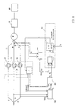
- FIG. 1 illustrates a device for controlling an electric motor M of three-phase asynchronous type.
- the motor M is mechanically connected to a load 30, such as a pump, to drive it; the pump is connected to a distribution circuit of fluid 40.
- the motor control method M makes it possible to detect a level of underload of pump 30.
- Underload means any anomaly occurring in the pump, for example its defusing, or in the distribution circuit, for example the closing of a valve causing a stop of the pump flow.
- Motor M is supplied from an alternative network via of a three-phase dimmer 10.
- the dimmer 10 includes three switches bi-directional semiconductor 11, 12, and 13; each switch is for example a pair of two thyristors mounted head to tail, and whose midpoint is connected, on the input side, to a phase R, S or T conductor of the network, and on the output side, to a respective phase A, B or C winding of motor M.
- Triggers of thyristors are controlled by a control circuit 20 to make them passable to selected moments in order to modulate the currents of the phases of the motor in particular at starting and slowing down of it.
- the dimmer 10 makes it possible to start the motor M and to increase its speed up to a steady speed which corresponds to the desired volume flow of the pump if it is of the volumetric type.
- the device of the invention comprises means 50 for controlling the electromagnetic torque C m of the engine.
- the torque is representative of the state of charge of the pump 30.
- a decrease in the torque C m reflects the fact that the motor M needs less power to drive the pump 30, which implies that, seen from the motor, the pump is in an underload state.
- the control means 50 comprise an estimation block 51 of the electromagnetic torque C m of the motor and a comparator 52 of the measured torque C m at a threshold value C s .
- the output of block 51 is connected to an input of comparator 52, the output of which is applied to the control circuit 20.
- the electromagnetic torque C m is the image of the power transmitted to the engine.
- the device of the invention comprises current reading members 60, a current calculating member 61, a block 62 for estimating the ignition delay a thyristors and a calculation block 63 of the delay ⁇ of the fundamental current on the network voltage.
- the current reading members 60 are connected to the current calculating member 61; the output of block 62 is connected to an input of block 63 and the outputs of blocks 63 and 61 are applied to inputs of block 51 for estimating the electromagnetic torque C m .
- the current reading members 60 are for example two in number, for supplying signals I A , I B , representative of the currents flowing in the phases A and B of the motor.
- the calculating member 61 located downstream of the reading members 60 makes it possible to extract each current fundamental (I A ) 1 , (I B ) 1 from the signals I A , I B.
- Block 62 is connected to conductors R, S of the network; it allows to estimate the delay in starting ⁇ of the current in the thyristors of phases A and B referenced on the single network voltage; this delay corresponds to the time between the instant for zero crossing of the single voltage applied to a phase of the dimmer side network and the instant of ignition of the current in the thyristors corresponding to the same phase.
- Block 62 reproduces the signal of the single voltage of phase R of the network from the measurement of the compound voltage V RS between phases R and S of the network.
- a means of evaluating the time ⁇ can for example consist of an internal counter in block 62; the counter is triggered at each zero crossing of the single voltage and delivers the time elapsed ⁇ 1 on the subsequent arrival of the event of initiation of the current I A in the pair 10 of thyristors emitted by the control circuit 20.
- the block 62 also estimates and delivers the ignition delay ⁇ 2 for phase B of the motor.
- the calculation block 63 receives as input on the one hand the values ⁇ 1 and ⁇ 2 transmitted by the block 62, and on the other hand a value ⁇ of the delay in the ignition of the thyristors referenced on the current and supplied by the circuit 20.
- the time ⁇ corresponds to the time elapsed between the instant of the last zero crossing of the current in one phase of the motor and the instant of restarting the current in this phase when the current changes sign.
- Block 63 outputs the values ⁇ 1 and ⁇ 2 of the delay of the fundamental of the current (I A ) 1 on the single voltage of phase R of the network and respectively of the delay of the fundamental of the current (I B ) 1 on the voltage simple of phase S of the network.
- the calculation block 51 of the torque C m receives as input the values ⁇ 1 and ⁇ 2 as well as the values of the fundamental of each current (I A ) 1 , (I B ) 1 .
- Block 51 calculates according to the input values and outputs the value of the electromagnetic torque C m equivalent to the proportional value of the power transmitted to the motor.
- Comparator 52 compares the estimated value of the electromagnetic torque C m with a configurable threshold value C s . It establishes a comparison result ⁇ which has a logical value 1 or else 0 corresponding, for example, respectively to a fault or else to normal operation of the pump 30 and / or of the distribution circuit 40. In the event of a fault, the comparator 52 sends to the control circuit 20 an inhibition signal S of the thyristor ignition.
- the process is implemented when the motor M has reached a speed steady state.
- the current reading members 60 deliver the current signals I A and I B flowing in the phases A and B of the motor. From these signals are deduced by means of the member 61 the fundamental values of each current (I A ) 1 , (I B ) 1 which are sent to block 51.
- block 62 estimates the values ⁇ 1 and ⁇ 2 of the ignition delay referenced on the voltage, these values are sent to block 63 which also receives the value ⁇ of the ignition delay referenced on the current. Block 63 in turn distributes to block 51 the values ⁇ 1 and ⁇ 2 of the delay of the fundamental of the current on the single voltage of the network.
- the calculation block 51 delivers and transmits to the comparator 52 the estimated value of the electromagnetic torque C m .
- Comparator 52 compares the torque C m with the threshold value C s for which it is estimated that the pump is under load.
- the comparator 52 sends the command circuit 20 no more prime the thyristors so as to no longer supply the motor which then stops in freewheel.
Landscapes
- Engineering & Computer Science (AREA)
- Power Engineering (AREA)
- Control Of Positive-Displacement Pumps (AREA)
- Control Of Ac Motors In General (AREA)
- Control Of Electric Motors In General (AREA)
Applications Claiming Priority (2)
| Application Number | Priority Date | Filing Date | Title |
|---|---|---|---|
| FR9609625A FR2751807B1 (fr) | 1996-07-29 | 1996-07-29 | Procede et dispositif de commande d'un moteur, notamment pour pompe |
| FR9609625 | 1996-07-29 |
Publications (2)
| Publication Number | Publication Date |
|---|---|
| EP0822653A1 true EP0822653A1 (de) | 1998-02-04 |
| EP0822653B1 EP0822653B1 (de) | 2001-08-22 |
Family
ID=9494663
Family Applications (1)
| Application Number | Title | Priority Date | Filing Date |
|---|---|---|---|
| EP19970401653 Expired - Lifetime EP0822653B1 (de) | 1996-07-29 | 1997-07-09 | Steuervorrichtung für einen Motor, insbesondere für eine Pumpe |
Country Status (4)
| Country | Link |
|---|---|
| EP (1) | EP0822653B1 (de) |
| DE (1) | DE69706254T2 (de) |
| DK (1) | DK0822653T3 (de) |
| FR (1) | FR2751807B1 (de) |
Cited By (1)
| Publication number | Priority date | Publication date | Assignee | Title |
|---|---|---|---|---|
| CN103047102A (zh) * | 2013-01-23 | 2013-04-17 | 邵军 | 一种扬水系统 |
Citations (5)
| Publication number | Priority date | Publication date | Assignee | Title |
|---|---|---|---|---|
| EP0030497A1 (de) * | 1979-12-07 | 1981-06-17 | Telemecanique | Schaltung zur Bestimmung des durch einen elektrischen Asynchronmotor gelieferten Kräftepaars |
| EP0246769A2 (de) * | 1986-05-22 | 1987-11-25 | FRANKLIN ELECTRIC Co., Inc. | Unterlastschutz für einen Elektromotor |
| US4841404A (en) * | 1987-10-07 | 1989-06-20 | Spring Valley Associates, Inc. | Pump and electric motor protector |
| EP0404540A1 (de) * | 1989-06-21 | 1990-12-27 | Shin Caterpillar Mitsubishi Ltd. | Anlage, um eine Pumpvorrichtung zu steuern |
| DE4312549A1 (de) * | 1993-04-17 | 1994-10-20 | Licentia Gmbh | Verfahren zur Drehmomentbegrenzung beim Sanftanlauf von Drehstromasynchronmotoren |
Family Cites Families (1)
| Publication number | Priority date | Publication date | Assignee | Title |
|---|---|---|---|---|
| FR2733863B1 (fr) * | 1995-05-05 | 1997-06-06 | Schneider Electric Sa | Procede de commande d'un gradateur et dispositif pour la mise en oeuvre de ce procede |
-
1996
- 1996-07-29 FR FR9609625A patent/FR2751807B1/fr not_active Expired - Lifetime
-
1997
- 1997-07-09 DK DK97401653T patent/DK0822653T3/da active
- 1997-07-09 EP EP19970401653 patent/EP0822653B1/de not_active Expired - Lifetime
- 1997-07-09 DE DE1997606254 patent/DE69706254T2/de not_active Expired - Lifetime
Patent Citations (5)
| Publication number | Priority date | Publication date | Assignee | Title |
|---|---|---|---|---|
| EP0030497A1 (de) * | 1979-12-07 | 1981-06-17 | Telemecanique | Schaltung zur Bestimmung des durch einen elektrischen Asynchronmotor gelieferten Kräftepaars |
| EP0246769A2 (de) * | 1986-05-22 | 1987-11-25 | FRANKLIN ELECTRIC Co., Inc. | Unterlastschutz für einen Elektromotor |
| US4841404A (en) * | 1987-10-07 | 1989-06-20 | Spring Valley Associates, Inc. | Pump and electric motor protector |
| EP0404540A1 (de) * | 1989-06-21 | 1990-12-27 | Shin Caterpillar Mitsubishi Ltd. | Anlage, um eine Pumpvorrichtung zu steuern |
| DE4312549A1 (de) * | 1993-04-17 | 1994-10-20 | Licentia Gmbh | Verfahren zur Drehmomentbegrenzung beim Sanftanlauf von Drehstromasynchronmotoren |
Cited By (2)
| Publication number | Priority date | Publication date | Assignee | Title |
|---|---|---|---|---|
| CN103047102A (zh) * | 2013-01-23 | 2013-04-17 | 邵军 | 一种扬水系统 |
| CN103047102B (zh) * | 2013-01-23 | 2016-02-03 | 邵军 | 一种扬水系统 |
Also Published As
| Publication number | Publication date |
|---|---|
| EP0822653B1 (de) | 2001-08-22 |
| FR2751807A1 (fr) | 1998-01-30 |
| FR2751807B1 (fr) | 1998-08-28 |
| DE69706254T2 (de) | 2002-01-03 |
| DK0822653T3 (da) | 2001-11-26 |
| DE69706254D1 (de) | 2001-09-27 |
Similar Documents
| Publication | Publication Date | Title |
|---|---|---|
| EP0741448B1 (de) | Anlaufsteuerungsverfahren und Vorrichtung zu dessen Betrieb | |
| EP1466336B1 (de) | Verfahren zum feststellen von kontaktverschleiss eines elektrischen gerätes | |
| EP0802606B1 (de) | Verfahren zur Steuerung des Erregungstroms eines Fahrzeuggenerators mit digitaler Verarbeitung und Steuerungsvorrichtung zur Durchführung dieses Verfahrens | |
| FR2863115A1 (fr) | Interrupteur de circuit en cas de defaut a la terre. | |
| EP0802464A1 (de) | Verfahren zur Steuerung des Erregungstroms eines Fahrzeuggenerators mit digitaler Verarbeitung und Steuerungsvorrichtung zur Durchführung dieses Verfahrens | |
| EP0822653B1 (de) | Steuervorrichtung für einen Motor, insbesondere für eine Pumpe | |
| FR2729256A1 (fr) | Methode et dispositif de controle d'un moteur synchrone monophase a aimants permanents apte a optimiser les parametres de fonctionnement meme en presence de fluctuations de la tension ou de la charge | |
| EP0021320B1 (de) | Gangdetektionsschaltung für Schrittmotor | |
| FR2814869A1 (fr) | Appareil de commande d'un generateur d'energie pour vehicule ayant une fonction de limitation d'intensite de conduction maximale | |
| FR2717252A1 (fr) | Installation équipée d'un système automatique de réglage d'un chauffage. | |
| FR2497038A1 (fr) | Generateur de courant asservi en puissance, notamment pour processus de decharge dans une atmosphere rarefiee | |
| EP1673854A1 (de) | Vorrichtung für synchrongleichrichtung und zugehörige synchronmaschine | |
| EP0823776B1 (de) | Bremsverfahren für einen elektrischen Motor und Vorrichtung zur Durchführung | |
| EP0982825A1 (de) | Drehzahlregelvorrichtung für einen elektrischen Motor und Vorrichtung zum Schleudern mit einer solchen Vorrichtung | |
| FR2773016A1 (fr) | Appareil de commande d'un moteur electrique | |
| FR2566204A1 (fr) | Dispositif de regulation de la vitesse d'un moteur electrique asynchrone | |
| FR2721999A1 (fr) | Debimetre massique redondant | |
| EP0016714A1 (de) | Verbesserte Anlage zum Steuern der Geschwindigkeitsänderungen der Nockengeräte einer Textilmaschine | |
| FR2542937A1 (fr) | Dispositif d'alimentation electrique du moteur d'une machine electro-portative assurant la protection contre le couple de reaction produit par celle-ci | |
| FR2488753A1 (fr) | Commande de moteur electrique a courant alternatif | |
| FR2568428A1 (fr) | Procede et installation de regulation en tension d'une machine asynchrone utilisee en generatrice autonome, par variation echelonnee d'une batterie de condensateurs connectes sur le reseau. | |
| FR2494053A1 (fr) | Dispositif de protection contre une diode en court-circuit pour un alternateur | |
| EP1414147B1 (de) | Messverfahren für die von einem Motor abgegebene Leistung | |
| FR2542093A1 (fr) | Procede et dispositif de mesure du glissement d'un moteur | |
| EP0030497A1 (de) | Schaltung zur Bestimmung des durch einen elektrischen Asynchronmotor gelieferten Kräftepaars |
Legal Events
| Date | Code | Title | Description |
|---|---|---|---|
| PUAI | Public reference made under article 153(3) epc to a published international application that has entered the european phase |
Free format text: ORIGINAL CODE: 0009012 |
|
| AK | Designated contracting states |
Kind code of ref document: A1 Designated state(s): CH DE DK GB IT LI SE |
|
| 17P | Request for examination filed |
Effective date: 19980414 |
|
| AKX | Designation fees paid |
Free format text: CH DE DK GB IT LI SE |
|
| RBV | Designated contracting states (corrected) |
Designated state(s): CH DE DK GB IT LI SE |
|
| RAP1 | Party data changed (applicant data changed or rights of an application transferred) |
Owner name: SCHNEIDER ELECTRIC INDUSTRIES SA |
|
| 17Q | First examination report despatched |
Effective date: 19991122 |
|
| RAP1 | Party data changed (applicant data changed or rights of an application transferred) |
Owner name: SCHNEIDER ELECTRIC INDUSTRIES SA |
|
| GRAG | Despatch of communication of intention to grant |
Free format text: ORIGINAL CODE: EPIDOS AGRA |
|
| GRAG | Despatch of communication of intention to grant |
Free format text: ORIGINAL CODE: EPIDOS AGRA |
|
| GRAH | Despatch of communication of intention to grant a patent |
Free format text: ORIGINAL CODE: EPIDOS IGRA |
|
| GRAH | Despatch of communication of intention to grant a patent |
Free format text: ORIGINAL CODE: EPIDOS IGRA |
|
| GRAA | (expected) grant |
Free format text: ORIGINAL CODE: 0009210 |
|
| AK | Designated contracting states |
Kind code of ref document: B1 Designated state(s): CH DE DK GB IT LI SE |
|
| REG | Reference to a national code |
Ref country code: CH Ref legal event code: EP |
|
| GBT | Gb: translation of ep patent filed (gb section 77(6)(a)/1977) |
Effective date: 20010822 |
|
| REF | Corresponds to: |
Ref document number: 69706254 Country of ref document: DE Date of ref document: 20010927 |
|
| ITF | It: translation for a ep patent filed | ||
| REG | Reference to a national code |
Ref country code: DK Ref legal event code: T3 |
|
| REG | Reference to a national code |
Ref country code: GB Ref legal event code: IF02 |
|
| PLBE | No opposition filed within time limit |
Free format text: ORIGINAL CODE: 0009261 |
|
| STAA | Information on the status of an ep patent application or granted ep patent |
Free format text: STATUS: NO OPPOSITION FILED WITHIN TIME LIMIT |
|
| 26N | No opposition filed |
Opponent name: KONINKLIJKE PHILIPS ELECTRONICS N.V. |
|
| PGFP | Annual fee paid to national office [announced via postgrant information from national office to epo] |
Ref country code: DK Payment date: 20080620 Year of fee payment: 12 |
|
| PGFP | Annual fee paid to national office [announced via postgrant information from national office to epo] |
Ref country code: CH Payment date: 20080715 Year of fee payment: 12 |
|
| REG | Reference to a national code |
Ref country code: CH Ref legal event code: PL |
|
| REG | Reference to a national code |
Ref country code: DK Ref legal event code: EBP |
|
| PG25 | Lapsed in a contracting state [announced via postgrant information from national office to epo] |
Ref country code: LI Free format text: LAPSE BECAUSE OF NON-PAYMENT OF DUE FEES Effective date: 20090731 Ref country code: CH Free format text: LAPSE BECAUSE OF NON-PAYMENT OF DUE FEES Effective date: 20090731 |
|
| PG25 | Lapsed in a contracting state [announced via postgrant information from national office to epo] |
Ref country code: DK Free format text: LAPSE BECAUSE OF NON-PAYMENT OF DUE FEES Effective date: 20090731 |
|
| REG | Reference to a national code |
Ref country code: DE Ref legal event code: R084 Ref document number: 69706254 Country of ref document: DE Effective date: 20111228 |
|
| PGFP | Annual fee paid to national office [announced via postgrant information from national office to epo] |
Ref country code: GB Payment date: 20150717 Year of fee payment: 19 Ref country code: DE Payment date: 20150620 Year of fee payment: 19 |
|
| PGFP | Annual fee paid to national office [announced via postgrant information from national office to epo] |
Ref country code: SE Payment date: 20150714 Year of fee payment: 19 |
|
| PGFP | Annual fee paid to national office [announced via postgrant information from national office to epo] |
Ref country code: IT Payment date: 20150710 Year of fee payment: 19 |
|
| REG | Reference to a national code |
Ref country code: DE Ref legal event code: R119 Ref document number: 69706254 Country of ref document: DE |
|
| REG | Reference to a national code |
Ref country code: SE Ref legal event code: EUG |
|
| GBPC | Gb: european patent ceased through non-payment of renewal fee |
Effective date: 20160709 |
|
| PG25 | Lapsed in a contracting state [announced via postgrant information from national office to epo] |
Ref country code: SE Free format text: LAPSE BECAUSE OF NON-PAYMENT OF DUE FEES Effective date: 20160710 Ref country code: DE Free format text: LAPSE BECAUSE OF NON-PAYMENT OF DUE FEES Effective date: 20170201 |
|
| PG25 | Lapsed in a contracting state [announced via postgrant information from national office to epo] |
Ref country code: GB Free format text: LAPSE BECAUSE OF NON-PAYMENT OF DUE FEES Effective date: 20160709 |
|
| PG25 | Lapsed in a contracting state [announced via postgrant information from national office to epo] |
Ref country code: IT Free format text: LAPSE BECAUSE OF NON-PAYMENT OF DUE FEES Effective date: 20160709 |