EP0822849B2 - Transportable löschpistole - Google Patents
Transportable löschpistole Download PDFInfo
- Publication number
- EP0822849B2 EP0822849B2 EP96914942A EP96914942A EP0822849B2 EP 0822849 B2 EP0822849 B2 EP 0822849B2 EP 96914942 A EP96914942 A EP 96914942A EP 96914942 A EP96914942 A EP 96914942A EP 0822849 B2 EP0822849 B2 EP 0822849B2
- Authority
- EP
- European Patent Office
- Prior art keywords
- extinguishing
- nozzles
- fluid
- nozzle head
- nozzle
- Prior art date
- Legal status (The legal status is an assumption and is not a legal conclusion. Google has not performed a legal analysis and makes no representation as to the accuracy of the status listed.)
- Expired - Lifetime
Links
- 239000012530 fluid Substances 0.000 claims description 27
- 239000003595 mist Substances 0.000 claims description 20
- 206010016322 Feeling abnormal Diseases 0.000 claims 1
- 239000003795 chemical substances by application Substances 0.000 description 4
- 238000010791 quenching Methods 0.000 description 4
- 230000000171 quenching effect Effects 0.000 description 4
- 239000007788 liquid Substances 0.000 description 3
- QVGXLLKOCUKJST-UHFFFAOYSA-N atomic oxygen Chemical compound [O] QVGXLLKOCUKJST-UHFFFAOYSA-N 0.000 description 2
- 230000006378 damage Effects 0.000 description 2
- 239000000203 mixture Substances 0.000 description 2
- 239000001301 oxygen Substances 0.000 description 2
- 229910052760 oxygen Inorganic materials 0.000 description 2
- 208000027418 Wounds and injury Diseases 0.000 description 1
- 230000009286 beneficial effect Effects 0.000 description 1
- 238000002485 combustion reaction Methods 0.000 description 1
- 239000002131 composite material Substances 0.000 description 1
- 238000001816 cooling Methods 0.000 description 1
- 238000012217 deletion Methods 0.000 description 1
- 230000037430 deletion Effects 0.000 description 1
- 238000009826 distribution Methods 0.000 description 1
- 230000002349 favourable effect Effects 0.000 description 1
- 238000010304 firing Methods 0.000 description 1
- 239000007789 gas Substances 0.000 description 1
- 208000014674 injury Diseases 0.000 description 1
- 238000000034 method Methods 0.000 description 1
- 238000005507 spraying Methods 0.000 description 1
- 238000009827 uniform distribution Methods 0.000 description 1
- XLYOFNOQVPJJNP-UHFFFAOYSA-N water Substances O XLYOFNOQVPJJNP-UHFFFAOYSA-N 0.000 description 1
Images

Classifications
-
- A—HUMAN NECESSITIES
- A62—LIFE-SAVING; FIRE-FIGHTING
- A62C—FIRE-FIGHTING
- A62C31/00—Delivery of fire-extinguishing material
- A62C31/02—Nozzles specially adapted for fire-extinguishing
- A62C31/05—Nozzles specially adapted for fire-extinguishing with two or more outlets
-
- A—HUMAN NECESSITIES
- A62—LIFE-SAVING; FIRE-FIGHTING
- A62C—FIRE-FIGHTING
- A62C31/00—Delivery of fire-extinguishing material
- A62C31/02—Nozzles specially adapted for fire-extinguishing
-
- B—PERFORMING OPERATIONS; TRANSPORTING
- B05—SPRAYING OR ATOMISING IN GENERAL; APPLYING FLUENT MATERIALS TO SURFACES, IN GENERAL
- B05B—SPRAYING APPARATUS; ATOMISING APPARATUS; NOZZLES
- B05B1/00—Nozzles, spray heads or other outlets, with or without auxiliary devices such as valves, heating means
- B05B1/14—Nozzles, spray heads or other outlets, with or without auxiliary devices such as valves, heating means with multiple outlet openings; with strainers in or outside the outlet opening
Definitions
- the invention relates to a transportable extinguishing gun, which has a quenching nozzle head, which is equipped at its front free end face with a plurality of spaced apart extinguishing nozzles, which are connectable to a supply line supplying extinguishing fluid and with which a fluid mist can be generated upon exposure to extinguishing fluid.
- a fire extinguisher of the type mentioned in the introduction is known from US Pat. No. 3,704,831.
- the nozzle head is rotatably arranged such that the nozzle openings arranged on the end face can be made to coincide by a rotation of the head with the outlet opening of an extinguishing fluid supply line. In this way, each one of the nozzles exits an extinguishing agent jet.
- one of the extinguishing nozzles is designed such that it generates an extinguishing mist when exposed to extinguishing fluid.
- the extinguishing fluid exits with a relatively high kinetic energy.
- the advantage of using such an extinguishing fluid jet is that the extinguishing agent jet can be introduced into the area of the fire with a long range. In this way, among other things, the firefighter who operates the extinguishing system, exposed only a small risk of injury. In order to achieve this, in the past the water damage caused by the always required large amount of extinguishing agent to extinguish a fire has been accepted as inevitable.
- a quenching nozzle head for stationary extinguishing systems which also has at its front, free end face a plurality of extinguishing nozzles.
- Each of these extinguishing nozzles generates an extinguishing mist when exposed to extinguishing fluid taken from a pressure accumulator.
- a central nozzle of the extinguishing nozzle head alone or all nozzles of the extinguishing nozzle head are acted upon together with fluid.
- a piston which shuts off the flow to the extinguishing nozzles arranged laterally of the central nozzle when the pressure in the supply line drops below a minimum value.
- extinguishing fluid can be discharged from the extinguishing nozzle head when the pressure discharged from the accumulator pressure drops so far that at full opening all extinguishing nozzles proper generation of the extinguishing mist would no longer be guaranteed.
- the operation of the extinguishing nozzle head is firmly coupled to the pressure curve in the supply line, it can not be guaranteed when using such a nozzle that at all times the optimum for fighting a fire extinguishing mist is available.
- the object of the invention is to improve a fire extinguisher of the type mentioned in that it reduces the amount of fluid required to extinguish a fire at an increased efficiency of the fluid mist.
- extinguishing nozzles instead of or in addition to a central main nozzle to provide more extinguishing nozzles, which produce a finely dispersed extinguishing mist,
- the individual extinguishing nozzles each of which, depending on the application, for example, fog of other nature and composition can produce their number, their respective Operation, the nature of their exposure to extinguishing fluid and their positioning on the extinguishing nozzle head, it is possible to produce a Löschnebel of special quality.
- This extinguishing mist is optimally composed, inter alia, with regard to the nature and size of the individual mist droplets contained in it.
- the extinguishing pistol according to the invention makes it possible, during the firing order, to adapt the type and composition of the generated extinguishing mist to the requirements which change as extinguishing success progresses.
- a valve combination optionally one of the extinguishing nozzles for themselves and / or groups of extinguishing nozzles are acted upon with extinguishing fluid.
- different extinguishing nozzle combinations can be used to produce a composite with a wide range of different fluid droplets Löschnebel.
- the individual extinguishing nozzles can be arranged in a line next to each other. This can be beneficial for those cases where a uniform extinguishing mist outlet is desired over a large area.
- the nozzles can also be arranged on the circumferential line of a circular arc or on a closed circle.
- An advantageous with regard to easy maintainability of the extinguishing gun embodiment is characterized in that the extinguishing nozzle head is releasably secured to a support unit.
- the rapid distribution of the extinguishing mist in the largest possible space can be facilitated by the fact that at least a certain number of extinguishing nozzles are arranged on an obliquely backward receding surface portion of the front end face of the extinguishing nozzle head.
- the speed with which a volume of space can be filled can be further increased by the fact that the extinguishing nozzle head has a side surface on which at least one extinguishing nozzle is additionally arranged.
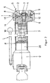
- the portable extinguishing pistol shown in Fig. 2 has a quenching nozzle head 1, which is constructed rotationally symmetrical and on whose end face S an end face 2 is formed. In the center of the end face 2, a recess 3 is formed, which receives a central extinguishing nozzle 4.
- the central extinguishing nozzle 4 is screwed into a screw receptacle 5 of a support unit 6, which is connected to a first supply line 7 and fixed to the housing tube R of the portable fire extinguisher L.
- a circumferential surface section 8 which is conical and recedes at an angle ⁇ with respect to the front end face 2.
- extinguishing nozzles 9 are arranged, which are connected to a second supply line 10.
- the extinguishing nozzles 9 are arranged at regular angular intervals ⁇ to each other on a circle K, which is aligned concentrically with the opening 4a of the central extinguishing nozzle 4.
- the extinguishing nozzles 9 Upon pressurization of the supply line 10, the extinguishing nozzles 9 generate an extinguishing mist, in which the individual liquid droplets have a low volume and emerge finely distributed from the nozzle openings 9a of the extinguishing nozzles 9 in the environment of a fire.
- the extinguishing nozzles 9 In order to enable a replacement of the extinguishing nozzles 9 in a simple manner, they are screwed detachably into screw receptacles 11, which are connected to the second supply line 10.
- a radially encircling side surface 12 connects.
- the side surface 12 are at regular angular intervals ⁇ spaced apart further extinguishing nozzles 13 are arranged, which can be acted upon by a third, not shown supply line with pressure.
- the extinguishing nozzle heads 13 are also located in screw receptacles 14 releasably and can be easily replaced when worn.
- the extinguishing nozzles 9 can be acted upon jointly as a group with extinguishing fluid via the second supply line 10.
- the extinguishing nozzles 13 are acted as a group together on the third, not shown supply line with extinguishing fluid. This makes it possible to independently apply extinguishing fluid to the central extinguishing nozzle 4, the group formed by the extinguishing nozzles 9, and the group formed by the extinguishing nozzles 13, respectively.
- valve combination V Via an intermediate disc 20 provided with oblique bores, the outlet channels of the valve combination V associated with the two supply lines 7, 10 and the third supply line (not shown) are connected to the supply lines 7, 10 and the third supply line (not shown).
- the washer 20 By using the washer 20, it is possible to design the valve housing of the valve combination simple and at the same time to choose the arrangement of the supply line 7,10 and the third supply line so that they occupy as small a space as possible.
Landscapes
- Health & Medical Sciences (AREA)
- Public Health (AREA)
- Business, Economics & Management (AREA)
- Emergency Management (AREA)
- Nozzles (AREA)
- Fire-Extinguishing By Fire Departments, And Fire-Extinguishing Equipment And Control Thereof (AREA)
- Shovels (AREA)
- Specific Sealing Or Ventilating Devices For Doors And Windows (AREA)
- Diaphragms For Electromechanical Transducers (AREA)
- Fire-Extinguishing Compositions (AREA)
Description
- Die Erfindung betrifft eine transportable Löschpistole, welche einen Löschdüsenkopf aufweist, der an seiner vorderen freien Stirnseite mit einer Mehrzahl von beabstandet zueinander angeordneten Löschdüsen bestückt ist, welche mit einer Löschfluid zuführenden Versorgungsleitung verbindbar sind und mit denen bei Beaufschlagung mit Löschfluid ein Fluidnebel erzeugbar ist.
- Eine Löschpistole der eingangs genannten Art ist aus den US-Patent US 3 704 831 bekannt. Bei der bekannten Pistole ist der Düsenkopf drehbar derart angeordnet, daß die auf der Stirnfläche angeordneten Düsenöffnungen durch eine Verdrehung des Kopfes mit der Austrittsöffnung einer Löschfluidversorgungsleitung zur Deckung gebrachtwerden können. Auf diese Weise tritt jeweils aus einer der Düsen ein Löschmittelstrahl aus. Dabei ist eine der Löschdüsen derart ausgebildet, daß sie bei Beaufschlagung mit Löschfluid einen Löschnebel erzeugt.
- Bei der bekannten Löschpistole tritt das Löschfluid mit einer relativ hohen kinetischen Energie aus. Der Vorteil der Verwendung eines solchen Löschfluidstrahls besteht darin, daß der Löschmittelstrahl mit einer großen Reichweite in den Bereich des Brandes eingebracht werden kann. Auf diese Weise ist unter anderem der Feuerwehrmann, welcher die Löschanlage bedient, nur einem geringen Verletzungsrisiko ausgesetzt. Um dies zu erreichen, wurden in der Vergangenheit die Wasserschäden als unvermeidlich hingenommen, die durch die stets erforderlichen großen Menge an Löschmittel zum Löschen eines Feuers verursacht werden.
- Neben der voranstehend erläuterten bekannten Löschpistole ist aus der internationalen Anmeldung WO94/25112 ein stationär zu befestigender Löschdüsenhalter bekannt, bei dem die Löschdüsen auf einer schrägen, kegelförmig ausgebildeten Außenfläche angeordnet sind. Der Vorteil einer solchen Ausbildung des Löschdüsenhalters besteht darin, daß über die Löschdüsen ein relativ großes Raumvolumen kurzfristig mit Löschfluid überstrichen werden kann.
- Neben den herkömmlichen Löschverfahren, bei denen große Mengen von Löschfluid in den Brandherd geleitet werden, ist es bekannt, zum Löschen eines Feuers einen Fluidnebel einzusetzen. Durch das Einsprühen eines derartigen Flüssigkeitsnebels in die Umgebung des Brandherdes wird die Temperatur der den Brandherd umgebenden Gase herabgesenkt. Gleichzeitig wird der für den Verbrennungsvorgang benötigte Sauerstoff aus der Umgebung des Brandes verdrängt. Durch die Temperaturherabsetzung und die Verdrängung des Sauerstoffs wird schließlich der Brand erstickt. Dabei liegt ein weiterer besonderer Vorteil des Löschens mit einem Fluidnebel darin, daß nur geringe Flüssigkeitsmengen zum Löschen benötigt werden.
- Aus der WO-A-92/20453 ist ein Löschdüsenkopf für stationäre Löschanlagen bekannt, welcher ebenfalls an seiner vorderen, freien Stirnseite eine Mehrzahl von Löschdüsen besitzt. Jede dieser Löschdüsen erzeugt bei Beaufschlagung mit aus einem Druckspeicher entnommenen Löschfluid einen Löschnebel. Abhängig vom Druck in der Versorgungsleitung, über welche der Löschdüsenkopf mit Löschfluid versorgt wird, werden eine zentrale Düse des Löschdüsenkopfes alleine oder alle Düsen des Löschdüsenkopfes gemeinsam mit Fluid beaufschlagt. Zu diesem Zweck ist ein Kolben vorgesehen, der den Zufluß zu den seitlich der zentralen Düse angeordneten Löschdüsen absperrt, wenn der Druck in der Versorgungsleitung unter einen Mindestwert sinkt. Auf diese Weise kann zumindest aus der zentralen Löschdüse auch dann noch Löschfluid aus dem Löschdüsenkopf ausgebracht werden, wenn der von dem Druckspeicher abgegebene Druck soweit absinkt, daß bei voller Öffnung aller Löschdüsen eine ordnungsgemäße Erzeugung des Löschnebels nicht mehr gewährleistet wäre. Da die Funktionsweise des Löschdüsenkopfes jedoch fest mit dem Druckverlauf in der Versorgungsleitung gekoppelt ist, kann bei Verwendung eines solchen Löschdüsenkopfes nicht gewährleistet werden, daß zu jedem Zeitpunkt der für die Bekämpfung eines Brandes optimale Löschnebel zur Verfügung steht.
- Die Aufgabe der Erfindung besteht darin, eine Löschpistole der eingangs genannten Art dahingehend zu verbessern, daß bei ihr die zum Löschen eines Feuers benötigte Fluidmenge bei einer gesteigerten Wirksamkeit des Fluidnebels reduziert ist.
- Diese Aufgabe wird durch eine transportable Löschpistole nach Anspruch 1 gelöst.
- Erfindungsgemäß ist vorgesehen, anstelle von oder zusätzlich zu einer zentralen Hauptdüse weitere Löschdüsen vorzusehen, welche einen fein verteilten Löschnebel erzeugen, Durch die Auswahl der einzelnen Löschdüsen, von denen jede je nach Anwendungsfall beispielsweise Nebel anderer Art und Zusammensetzung erzeugen kann, ihre Anzahl, ihre jeweilige Betriebsweise, die Art ihrer Beaufschlagung mit Löschfluid und ihre Positionierung auf dem Löschdüsenkopf ist es möglich, einen Löschnebel von besonderer Qualität zu erzeugen. Dieser Löschnebel ist unter anderem hinsichtlich der Art und Größe der in ihm enthaltenen einzelnen Nebeltröpfchen optimal zusammengesetzt.
- Darüber hinaus ermöglicht es die erfindungsgemäße Löschpistole, während des Löscheinsatzes die Art und Zusammensetzung des erzeugten Löschnebels an die sich mit fortschreitendem Löscherfolg ändernden Anforderungen anzupassen. Dies wird dadurch erreicht, dass über eine Ventilkombination wahlweise eine der Löschdüsen für sich und/oder Gruppen der Löschdüsen mit Löschfluid beaufschlagbar sind. Auf diese Weise können beispielsweise verschiedene Löschdüsenkombinationen zur Erzeugung eines mit einem breiten Spektrum unterschiedlicher Fluidtröpfchen zusammengesetzten Löschnebels benutzt werden. Ebenso ist es beispielsweise im Hinblick auf eine möglichst schnelle Abkühlung der Raumtemperatur zu Beginn des Löschens möglich, eine Löschnebel zu erzeugen, der aus nur einer einzigen, besonders feinverteilten Tröpfchenform zusammengesetzt ist. Bei fortschreitendem Löscherfolg können dann durch Öffnen zusätzlicher Düsen diesem feinen Nebel größere Tropfen beigemischt werden, um beispielsweise Glutnester direkt zu bekämpfen.
- Je nach Anwendungsfall können die einzelnen Löschdüsen in einer Linie nebeneinander angeordnet sein. Dies kann für solche Fälle günstig sein, bei denen über eine große Fläche ein gleichmäßiger Löschnebelaustritt gewünscht wird. Alternativ oder ergänzend können die Düsen auch auf der Umfangslinie eines Kreissbogens oder auf einem geschlossenen Kreises angeordnet sein.
- Für den Fall, daß neben den auf der Stirnseite angeordneten Löschdüsen eine zusätzliche Hauptdüse vorgesehen ist, aus der bei Bedarf kurzfristig größere Mengen Löschmittel ausgebrachtwerden können, ist es günstig, wenn der Mittelpunkt des Kreises oder des Kreisbogens, auf dem die Düsen angeordnet sind, im Mittelpunkt dieser zentral angeordneten Hauptdüse angeordnet ist. Eine gleichmäßige Verteilung des Löschnebels wird auch dadurch erreicht, daß die einzelnen Düsen in regelmäßig gleichem Abstand zueinander angeordnet sind.
- Eine im Hinblick auf eine einfache Wartbarkeit der Löschpistole vorteilhafte Ausgestaltung ist dadurch gekennzeichnet, daß der Löschdüsenkopf lösbar an einer Trägereinheit befestigt ist.
- Die schnelle Verteilung des Löschnebels in einem möglichst großen Raum kann dadurch begünstigt werden, daß mindestens eine bestimmte Anzahl von Löschdüsen auf einem schräg nach hinten zurückweichenden Flächenabschnitt der vorderen Stirnfläche des Löschdüsenkopfes angeordnet sind. Die Geschwindigkeit, mit der ein Raumvolumen gefüllt werden kann, kann noch dadurch gesteigert werden, daß der Löschdüsenkopf eine Seitenfläche aufweist, an der zusätzlich mindestens eine Löschdüse angeordnet ist.
- Weitere vorteilhafte Ausgestaltungen der Erfindung sind den Ansprüchen und der nachfolgenden Beispielsbeschreibung zu entnehmen. Darin wird die Erfindung anhand einer ein Ausführungsbeispiel darstellenden Zeichnung näher erläutert. Es zeigen:
- Fig. 1
- eine Löschdüsenkopf in frontaler Ansicht;
- Fig. 2
- eine Löschpistole in einem teilweise aufgebrochenen Längsschnitt.
- Die in Fig. 2 gezeigte transportable Löschpistole weist einen Löschdüsenkopf 1 auf, der rotationssymmetrisch aufgebaut ist und an dessen Stirnseite S eine Stirnfläche 2 ausgebildet ist. Im Zentrum der Stirnfläche 2 ist eine Ausnehmung 3 eingeformt, die eine zentrale Löschdüse 4 aufnimmt. Die zentrale Löschdüse 4 ist in eine Schraubenaufnahme 5 einer Trägereinheit 6 eingeschraubt, welche mit einer ersten Versorgungsleitung 7 verbunden und am Gehäuserohr R der transportablen Löschpistole L befestigt ist.
- An die Stirnfläche 2 angeformt ist ein umlaufender Flächenabschnitt 8, der konisch ausgebildet ist und gegenüber der vorderen Stirnfläche 2 in einem Winkel α zurückweicht. Auf dem Flächenabschnitt 8 sind Löschdüsen 9 angeordnet, welche mit einer zweiten Versorgungsleitung 10 verbunden sind. Die Löschdüsen 9 sind in regelmäßigen Winkelabständen β zueinander auf einem Kreis K angeordnet, der konzentrisch zur Öffnung 4a der zentralen Löschdüse 4 ausgerichtet ist. Bei Druckbeaufschlagung der Versorgungsleitung 10 erzeugen die Löschdüsen 9 einen Löschnebel, bei dem die einzelnen Flüssigkeitströpfchen ein geringes Volumen aufweisen und feinverteilt aus den Düsenöffnungen 9a der Löschdüsen 9 in die Umgebung eines Brandherdes austreten.
Um ein Austauschen der Löschdüsen 9 auf einfache Weise zu ermöglichen, sind diese in Schraubaufnahmen 11 lösbar eingeschraubt, welche mit der zweiten Versorgungsleitung 10 verbunden sind. - An den Flächenabschnitt 8 der Stirnseite S des Löschdüsenkopfes 1 schließt sich eine radial umlaufende Seitenfläche 12 an. In die Seitenfläche 12 sind in regelmäßigen Winkelabständen æ zueinander beabstandet weitere Löschdüsen 13 angeordnet, die über eine dritte, nicht gezeigte Versorgungsleitung mit Druck beaufschlagbar sind. Die Löschdüsenköpfe 13 sitzen ebenfalls in Schraubaufnahmen 14 lösbar ein und können bei Verschleiß auf einfache Weise ausgetauscht werden.
- Die Löschdüsen 9 sind gemeinsam als Gruppe mit Löschfluid über die zweite Versorgungsleitung 10 beaufschlagbar. Ebenso sind die Löschdüsen 13 als Gruppe gemeinsam über die dritte, nicht gezeigte Versorgungsleitung mit Löschfluid beaufschlagt. Dies ermöglicht es, die zentrale Löschdüse 4, die aus den Löschdüsen 9 gebildete Gruppe und die aus den Löschdüsen 13 gebildete Gruppe jeweils unabhängig voneinander mit Löschfluid zu beaufschlagen.
- Ebenso ist es möglich die beiden Gruppen von Löschdüsen 9,13 und die zentrale Löschdüse 4 in verschiedenen Kombinationen miteinander zu betreiben. Um dies zu erreichen, ist eine nicht näher erläuterte Ventilkombination V vorgesehen. Über eine mit Schrägbohrungen versehene Zwischenscheibe 20 sind die den beiden Versorgungsleitungen 7,10 und der dritten, nicht gezeigten Versorgungsleitung zugeordneten Austrittskanäle der Ventilkombination V mit den Versorgungsleitungen 7, 10 und der dritten, nicht gezeigten Versorgungsleitung verbunden. Durch die Verwendung der Zwischenscheibe 20 ist es möglich, das Ventilgehäuse der Ventilkombination einfach auszugestalten und gleichzeitig die Anordnung der Versorgungsleitung 7,10 und der dritten Versorgungsleitung so zu wählen, daß sie einen möglichst geringen Raum einnehmen.
Claims (7)
- Transportable Löschpistole (L),- welche einen Löschdüsenkopf (1)aufweist,- der an seiner vorderen freien Stirnseite (S) mit einer Mehrzahl von beabstandet zueinander angeordneten Löschdüsen (4,9) bestückt ist,- welche mit einer Löschfluid zuführenden Versorgungsleitung verbindbar sind und- von denen jede bei Beaufschlagung mit Löschfluid einen Fluidnebel erzeugen kann;- dadurch gekennzeichnet,- dass über eine Ventilkombination (V) wahlweise eine der Löschdüsen (4) für sich und/oder Gruppen der Löschdüsen (9) mit Löschfluid beaufschlagbar sind.
- Löschpistole nach Anspruch 1, dadurch gekennzeichnet, dass der Löschdüsenkopf (1) eine zentral auf der Stirnseite (S) angeordnete Löschdüse (4) aufweist.
- Löschpistole nach Anspruch 1 oder 2, dadurch gekennzeichnet, dass die Löschdüsen (9) in einer Linie nebeneinander, auf einem Kreisbogen oder einem geschlossenen Kreis (K) angeordnet sind.
- Löschpistole nach einem der voranstehenden Ansprüche, dadurch gekennzeichnet, dass die Löschdüsen (9) in einem regelmässig gleichen Abstand (β, ae) zueinander angeordnet sind.
- Löschpistole nach einem der voranstehenden Ansprüche, dadurch gekennzeichnet, dass der Löschdüsenkopf (1) lösbar an einer Trägereinheit(6) befestigt ist.
- Löschpistole nach einem der voranstehenden Ansprüche, dadurch gekennzeichnet, mindestens eine bestimmte Anzahl von Löschdüsen (9) auf einem schräg nach hinten zurückweichenden Flächenabschnitt (8) der vorderen Stirnfläche (2)des Löschdüsenkopfes (1) angeordnet sind.
- Löschpistole nach einem der voranstehenden Ansprüche, dadurch gekennzeichnet, dass der Löschdüsenkopf (1) eine Seitenfläche (12)aufweist, an der zusätzlich mindestens eine Düse (13) angeordnet ist.
Applications Claiming Priority (5)
| Application Number | Priority Date | Filing Date | Title |
|---|---|---|---|
| DE19514939 | 1995-04-22 | ||
| DE19514939A DE19514939C2 (de) | 1995-04-22 | 1995-04-22 | Löschdüsenkopf |
| DE29518911U | 1995-11-29 | ||
| DE29518911U DE29518911U1 (de) | 1995-04-22 | 1995-11-29 | Löschdüsenkopf, insbesondere für eine transportable Löschnebelpistole |
| PCT/EP1996/001622 WO1996033774A1 (de) | 1995-04-22 | 1996-04-18 | Transportable löschpistole |
Publications (3)
| Publication Number | Publication Date |
|---|---|
| EP0822849A1 EP0822849A1 (de) | 1998-02-11 |
| EP0822849B1 EP0822849B1 (de) | 2001-06-13 |
| EP0822849B2 true EP0822849B2 (de) | 2007-01-24 |
Family
ID=26014586
Family Applications (1)
| Application Number | Title | Priority Date | Filing Date |
|---|---|---|---|
| EP96914942A Expired - Lifetime EP0822849B2 (de) | 1995-04-22 | 1996-04-18 | Transportable löschpistole |
Country Status (7)
| Country | Link |
|---|---|
| US (1) | US6173909B1 (de) |
| EP (1) | EP0822849B2 (de) |
| JP (1) | JP3792719B2 (de) |
| AU (1) | AU5689696A (de) |
| DE (1) | DE29623240U1 (de) |
| ES (1) | ES2159735T5 (de) |
| WO (1) | WO1996033774A1 (de) |
Cited By (2)
| Publication number | Priority date | Publication date | Assignee | Title |
|---|---|---|---|---|
| CN102247676A (zh) * | 2011-07-20 | 2011-11-23 | 苏州辰泰鸿业安全技术有限公司 | 一种闭式高压细水雾喷头 |
| CN111481868A (zh) * | 2017-01-19 | 2020-08-04 | 维克托里克公司 | 直接联接的兼容式喷洒器 |
Families Citing this family (13)
| Publication number | Priority date | Publication date | Assignee | Title |
|---|---|---|---|---|
| FR2781697B1 (fr) * | 1998-07-15 | 2001-08-31 | Proteg Incendie | Buse de pulverisation de liquides |
| DE19841876C2 (de) * | 1998-09-11 | 2002-07-18 | Fogtec Brandschutz Gmbh & Co | Vorrichtung zur Erzeugung von Löschschaum |
| DE19841875A1 (de) * | 1998-09-11 | 2000-03-23 | Fogtec Brandschutz Gmbh | Löschdüsenkopf zum Ausbringen von Löschflüssigkeit |
| DE19841874A1 (de) * | 1998-09-11 | 2000-03-23 | Fogtec Brandschutz Gmbh | Verfahren und Vorrichtung zum Bekämpfen von Bränden |
| JP4553496B2 (ja) * | 2001-01-24 | 2010-09-29 | 株式会社日立国際電気 | 半導体製造装置のトレーニングシステム |
| DE10163102A1 (de) * | 2001-12-20 | 2003-07-10 | Alto Deutschland Gmbh | Hochdruckdüse, insbesondere für ein Hochdruckreinigungsgerät |
| CA2498838A1 (en) * | 2002-10-01 | 2004-04-15 | Aqua-Rack Enterprises | Firefighting system |
| DE10320856B3 (de) * | 2003-05-09 | 2004-09-23 | INT GmbH Ingenieurbüro für Neue Technologien, Anlagenbau, Verfahrenstechnik, ADFOSY | Mehrfach-Düsenkopf |
| TWI252118B (en) * | 2004-10-26 | 2006-04-01 | Ind Tech Res Inst | High pressure nozzle for spraying water mist |
| EP1741473A1 (de) * | 2005-07-07 | 2007-01-10 | Vogt AG Feuerwehrgeräte- und Fahrzeugbau | Einrichtung zum Belüften oder Entlüften eines Tunnels |
| KR101142726B1 (ko) * | 2011-09-26 | 2012-05-04 | 세보테크 주식회사 | 해양플랜트 버너 붐 워터 스프레이 시스템용 노즐 |
| US10207133B2 (en) * | 2014-09-01 | 2019-02-19 | ESI Energy Solutions, LLC. | Smart nozzle delivery system |
| DE102016212612B4 (de) * | 2016-07-11 | 2020-01-30 | Minimax Gmbh & Co. Kg | Feuerlöschvorrichtung zur Installation in einem Raum und zur Brandbekämpfung in mehreren Sektoren des Raums, sowie Feuerlöschanlage mit selbiger |
Citations (7)
| Publication number | Priority date | Publication date | Assignee | Title |
|---|---|---|---|---|
| US195643A (en) † | 1877-09-25 | Improvement in hose-nozzles | ||
| US236541A (en) † | 1881-01-11 | Nozzle and rose-sprinkler | ||
| US2342050A (en) † | 1942-07-28 | 1944-02-15 | Gordon F Hurst | Fog stream nozzle |
| US2364848A (en) † | 1944-01-19 | 1944-12-12 | Gordon F Hurst | Fog nozzle |
| GB629335A (en) † | 1946-05-20 | 1949-09-16 | Thompson Wilson Burnam | Fog nozzle for fire hoses |
| FR2339414A1 (fr) † | 1976-01-27 | 1977-08-26 | Hydrovide | Dispositif de lutte contre l'incendie |
| WO1994006517A1 (en) † | 1992-09-15 | 1994-03-31 | Sundholm Goeran | Method and device for fire extinguishing by alternating a liquid fog and a liquid jet |
Family Cites Families (7)
| Publication number | Priority date | Publication date | Assignee | Title |
|---|---|---|---|---|
| US2359455A (en) * | 1943-06-02 | 1944-10-03 | Marine Specialty Company Inc | Fire extinguishing nozzle |
| US2567176A (en) * | 1948-03-31 | 1951-09-11 | Edward D Ballard | Fire fighting nozzle |
| US4828178A (en) * | 1987-06-29 | 1989-05-09 | Hoechst Celanese Corporation | Method and apparatus for dispersing liquids or melts |
| DE3822160A1 (de) | 1988-06-30 | 1990-01-11 | Total Feuerschutz Gmbh | Verfahren und vorrichtung zum verstellen eines duesenkopfes |
| JP3631489B2 (ja) | 1991-05-20 | 2005-03-23 | マリオフ・コーポレーシヨン・オー・ワイ | 消火設備 |
| GB9322825D0 (en) * | 1993-11-05 | 1993-12-22 | Lo Mei K | A shower head |
| US5816505A (en) * | 1997-04-17 | 1998-10-06 | Ingersoll-Dresser Pump Company | Fluid jet decoking tool |
-
1996
- 1996-04-18 EP EP96914942A patent/EP0822849B2/de not_active Expired - Lifetime
- 1996-04-18 WO PCT/EP1996/001622 patent/WO1996033774A1/de not_active Ceased
- 1996-04-18 AU AU56896/96A patent/AU5689696A/en not_active Abandoned
- 1996-04-18 JP JP53214696A patent/JP3792719B2/ja not_active Expired - Fee Related
- 1996-04-18 US US08/945,569 patent/US6173909B1/en not_active Expired - Fee Related
- 1996-04-18 DE DE29623240U patent/DE29623240U1/de not_active Expired - Lifetime
- 1996-04-18 ES ES96914942T patent/ES2159735T5/es not_active Expired - Lifetime
Patent Citations (7)
| Publication number | Priority date | Publication date | Assignee | Title |
|---|---|---|---|---|
| US195643A (en) † | 1877-09-25 | Improvement in hose-nozzles | ||
| US236541A (en) † | 1881-01-11 | Nozzle and rose-sprinkler | ||
| US2342050A (en) † | 1942-07-28 | 1944-02-15 | Gordon F Hurst | Fog stream nozzle |
| US2364848A (en) † | 1944-01-19 | 1944-12-12 | Gordon F Hurst | Fog nozzle |
| GB629335A (en) † | 1946-05-20 | 1949-09-16 | Thompson Wilson Burnam | Fog nozzle for fire hoses |
| FR2339414A1 (fr) † | 1976-01-27 | 1977-08-26 | Hydrovide | Dispositif de lutte contre l'incendie |
| WO1994006517A1 (en) † | 1992-09-15 | 1994-03-31 | Sundholm Goeran | Method and device for fire extinguishing by alternating a liquid fog and a liquid jet |
Non-Patent Citations (2)
| Title |
|---|
| "WASSER LÖSCHMITTEL", Dr. Ing. Oskar Herterich, Dr. Alfred Hüthig Verlag Gmbh Heidelberg, 1960 † |
| Research report No. RTE 11311/95 März 1995 † |
Cited By (4)
| Publication number | Priority date | Publication date | Assignee | Title |
|---|---|---|---|---|
| CN102247676A (zh) * | 2011-07-20 | 2011-11-23 | 苏州辰泰鸿业安全技术有限公司 | 一种闭式高压细水雾喷头 |
| CN102247676B (zh) * | 2011-07-20 | 2013-01-02 | 苏州辰泰鸿业安全技术有限公司 | 一种闭式高压细水雾喷头 |
| CN111481868A (zh) * | 2017-01-19 | 2020-08-04 | 维克托里克公司 | 直接联接的兼容式喷洒器 |
| CN111481868B (zh) * | 2017-01-19 | 2022-03-01 | 维克托里克公司 | 直接联接的兼容式喷洒器 |
Also Published As
| Publication number | Publication date |
|---|---|
| US6173909B1 (en) | 2001-01-16 |
| ES2159735T5 (es) | 2007-10-01 |
| WO1996033774A1 (de) | 1996-10-31 |
| DE29623240U1 (de) | 1998-01-15 |
| JPH11503944A (ja) | 1999-04-06 |
| ES2159735T3 (es) | 2001-10-16 |
| JP3792719B2 (ja) | 2006-07-05 |
| EP0822849A1 (de) | 1998-02-11 |
| AU5689696A (en) | 1996-11-18 |
| EP0822849B1 (de) | 2001-06-13 |
Similar Documents
| Publication | Publication Date | Title |
|---|---|---|
| EP0822849B2 (de) | Transportable löschpistole | |
| DE69923360T2 (de) | Thermische Lichtbogenspritzpistole und ihre Gaskappe | |
| DE29518911U1 (de) | Löschdüsenkopf, insbesondere für eine transportable Löschnebelpistole | |
| DE1725022C3 (de) | Flammspritzspistole | |
| DE2724318A1 (de) | Verfahren und anlage zum druckluftstrahlen | |
| DE10010880B4 (de) | Verfahren und Vorrichtung zum Ausbringen von flüssigen Medien | |
| DE2841384A1 (de) | Zerstaeuberkopf fuer farbspritzpistolen | |
| DE69406006T2 (de) | Schaumlöschungssystem | |
| DE10393218B4 (de) | Vorrichtung zur Erzeugung eines Gas-Flüssigkeits-Gemisches im Bereich von Schrämwerkzeugen | |
| DE3443289C1 (de) | Verfahren zur Verminderung der Zuendung von Grubengas beim Arbeiten einer Teilschnitt-Streckenvortiebsmaschine | |
| EP0105047A1 (de) | Schrämkopf für Streckenvortriebsmaschinen | |
| DE69707252T2 (de) | Verfahren zur feuerbekämpfung und einrichtung zum löschen eines langestreckten gegenstandes | |
| DE1131603B (de) | Vorrichtung zum gleichmaessigen Verteilen von Fluessigkeiten ueber kreisbegrenzte Flaechen | |
| WO2002075228A1 (de) | Mit einer zerstäubungseinrichtung für flüssigkeiten versehene schneekanone | |
| DE19645004A1 (de) | Verfahren und Vorrichtung zur Erzeugung von Sprühnebel | |
| DE2113409C3 (de) | Verfahren und Vorrichtung zum Nachfüllen eines Lösungsmittels in ein dieses enthaltendes Acetylenflaschenbündel | |
| DE102020213695A1 (de) | Bündeldüse zum Versprühen eines Fluids, Anordnung mit einer Bündeldüse und Verfahren zum Herstellen einer Bündeldüse | |
| EP1112108B1 (de) | Löschdüsenkopf zum ausbringen von löschflüssigkeit | |
| WO1993000148A1 (de) | Nassreinigungseinrichtung, insbesondere zum abscheiden gasförmiger und/oder flüssiger und/oder fester verunreinigungen aus gasströmen | |
| DE869335C (de) | Duese zur Zerstaeubung von Wasser od. dgl. mittels Pressluft | |
| DE102014104341A1 (de) | Verfahren und Vorrichtung zur Erzeugung von Flüssigkeitsnebel | |
| DE3919653A1 (de) | Elektrostatische spritzpistole | |
| DE392944C (de) | Verfahren und Duesensystem zur Erhoehung der Wirtschaftlichkeit des Betriebes von Spritzapparaten | |
| DD141626A1 (de) | Drallduese zur erzeugung von spruehnebeln | |
| DE4041810A1 (de) | Mehrdraht-lichtbogen-spritzpistole zum drahtspritzen |
Legal Events
| Date | Code | Title | Description |
|---|---|---|---|
| PUAI | Public reference made under article 153(3) epc to a published international application that has entered the european phase |
Free format text: ORIGINAL CODE: 0009012 |
|
| 17P | Request for examination filed |
Effective date: 19971022 |
|
| AK | Designated contracting states |
Kind code of ref document: A1 Designated state(s): DE ES FR GB IT |
|
| 17Q | First examination report despatched |
Effective date: 19990427 |
|
| GRAG | Despatch of communication of intention to grant |
Free format text: ORIGINAL CODE: EPIDOS AGRA |
|
| GRAG | Despatch of communication of intention to grant |
Free format text: ORIGINAL CODE: EPIDOS AGRA |
|
| GRAH | Despatch of communication of intention to grant a patent |
Free format text: ORIGINAL CODE: EPIDOS IGRA |
|
| GRAH | Despatch of communication of intention to grant a patent |
Free format text: ORIGINAL CODE: EPIDOS IGRA |
|
| RAP1 | Party data changed (applicant data changed or rights of an application transferred) |
Owner name: FOGTEC BRANDSCHUTZ GMBH & CO. KG |
|
| GRAA | (expected) grant |
Free format text: ORIGINAL CODE: 0009210 |
|
| AK | Designated contracting states |
Kind code of ref document: B1 Designated state(s): DE ES FR GB IT |
|
| GBT | Gb: translation of ep patent filed (gb section 77(6)(a)/1977) |
Effective date: 20010613 |
|
| REF | Corresponds to: |
Ref document number: 59607094 Country of ref document: DE Date of ref document: 20010719 |
|
| ET | Fr: translation filed | ||
| ITF | It: translation for a ep patent filed | ||
| REG | Reference to a national code |
Ref country code: ES Ref legal event code: FG2A Ref document number: 2159735 Country of ref document: ES Kind code of ref document: T3 |
|
| REG | Reference to a national code |
Ref country code: GB Ref legal event code: IF02 |
|
| PLBQ | Unpublished change to opponent data |
Free format text: ORIGINAL CODE: EPIDOS OPPO |
|
| PLBI | Opposition filed |
Free format text: ORIGINAL CODE: 0009260 |
|
| PLBF | Reply of patent proprietor to notice(s) of opposition |
Free format text: ORIGINAL CODE: EPIDOS OBSO |
|
| 26 | Opposition filed |
Opponent name: MARIOFF CORPORATION OY Effective date: 20020312 |
|
| PLBF | Reply of patent proprietor to notice(s) of opposition |
Free format text: ORIGINAL CODE: EPIDOS OBSO |
|
| PLAY | Examination report in opposition despatched + time limit |
Free format text: ORIGINAL CODE: EPIDOSNORE2 |
|
| PLAY | Examination report in opposition despatched + time limit |
Free format text: ORIGINAL CODE: EPIDOSNORE2 |
|
| PLBC | Reply to examination report in opposition received |
Free format text: ORIGINAL CODE: EPIDOSNORE3 |
|
| PUAH | Patent maintained in amended form |
Free format text: ORIGINAL CODE: 0009272 |
|
| STAA | Information on the status of an ep patent application or granted ep patent |
Free format text: STATUS: PATENT MAINTAINED AS AMENDED |
|
| 27A | Patent maintained in amended form |
Effective date: 20070124 |
|
| AK | Designated contracting states |
Kind code of ref document: B2 Designated state(s): DE ES FR GB IT |
|
| GBTA | Gb: translation of amended ep patent filed (gb section 77(6)(b)/1977) |
Effective date: 20070404 |
|
| EN | Fr: translation not filed | ||
| REG | Reference to a national code |
Ref country code: ES Ref legal event code: DC2A Date of ref document: 20070423 Kind code of ref document: T5 |
|
| ET3 | Fr: translation filed ** decision concerning opposition | ||
| REG | Reference to a national code |
Ref country code: FR Ref legal event code: EERR Free format text: CORRECTION DE BOPI 07/37 - BREVETS EUROPEENS DONT LA TRADUCTION N A PAS ETE REMISE A L INPI. IL Y A LIEU DE SUPPRIMER : LA MENTION DE LA NON REMISE. LA REMISE DE LA TRADUCTION EST PUBLIEE DANS LE PRESENT BOPI. |
|
| PGFP | Annual fee paid to national office [announced via postgrant information from national office to epo] |
Ref country code: IT Payment date: 20080429 Year of fee payment: 13 |
|
| PGFP | Annual fee paid to national office [announced via postgrant information from national office to epo] |
Ref country code: GB Payment date: 20080423 Year of fee payment: 13 |
|
| GBPC | Gb: european patent ceased through non-payment of renewal fee |
Effective date: 20090418 |
|
| PG25 | Lapsed in a contracting state [announced via postgrant information from national office to epo] |
Ref country code: GB Free format text: LAPSE BECAUSE OF NON-PAYMENT OF DUE FEES Effective date: 20090418 |
|
| PGFP | Annual fee paid to national office [announced via postgrant information from national office to epo] |
Ref country code: FR Payment date: 20100504 Year of fee payment: 15 Ref country code: ES Payment date: 20100426 Year of fee payment: 15 |
|
| PG25 | Lapsed in a contracting state [announced via postgrant information from national office to epo] |
Ref country code: IT Free format text: LAPSE BECAUSE OF NON-PAYMENT OF DUE FEES Effective date: 20090418 |
|
| PGFP | Annual fee paid to national office [announced via postgrant information from national office to epo] |
Ref country code: DE Payment date: 20110415 Year of fee payment: 16 |
|
| REG | Reference to a national code |
Ref country code: FR Ref legal event code: ST Effective date: 20111230 |
|
| PG25 | Lapsed in a contracting state [announced via postgrant information from national office to epo] |
Ref country code: FR Free format text: LAPSE BECAUSE OF NON-PAYMENT OF DUE FEES Effective date: 20110502 |
|
| REG | Reference to a national code |
Ref country code: ES Ref legal event code: FD2A Effective date: 20120524 |
|
| PG25 | Lapsed in a contracting state [announced via postgrant information from national office to epo] |
Ref country code: ES Free format text: LAPSE BECAUSE OF NON-PAYMENT OF DUE FEES Effective date: 20110419 |
|
| REG | Reference to a national code |
Ref country code: DE Ref legal event code: R119 Ref document number: 59607094 Country of ref document: DE Effective date: 20121101 |
|
| PG25 | Lapsed in a contracting state [announced via postgrant information from national office to epo] |
Ref country code: DE Free format text: LAPSE BECAUSE OF NON-PAYMENT OF DUE FEES Effective date: 20121101 |