EP0822923B1 - Stabilisierung von wasser - Google Patents
Stabilisierung von wasser Download PDFInfo
- Publication number
- EP0822923B1 EP0822923B1 EP96911103A EP96911103A EP0822923B1 EP 0822923 B1 EP0822923 B1 EP 0822923B1 EP 96911103 A EP96911103 A EP 96911103A EP 96911103 A EP96911103 A EP 96911103A EP 0822923 B1 EP0822923 B1 EP 0822923B1
- Authority
- EP
- European Patent Office
- Prior art keywords
- water
- bed
- calcium carbonate
- line
- vessel
- Prior art date
- Legal status (The legal status is an assumption and is not a legal conclusion. Google has not performed a legal analysis and makes no representation as to the accuracy of the status listed.)
- Revoked
Links
- XLYOFNOQVPJJNP-UHFFFAOYSA-N water Substances O XLYOFNOQVPJJNP-UHFFFAOYSA-N 0.000 title claims abstract description 270
- 230000006641 stabilisation Effects 0.000 title claims description 13
- 238000011105 stabilization Methods 0.000 title claims description 13
- VTYYLEPIZMXCLO-UHFFFAOYSA-L Calcium carbonate Chemical compound [Ca+2].[O-]C([O-])=O VTYYLEPIZMXCLO-UHFFFAOYSA-L 0.000 claims abstract description 202
- 229910000019 calcium carbonate Inorganic materials 0.000 claims abstract description 101
- 238000000034 method Methods 0.000 claims abstract description 46
- 239000002245 particle Substances 0.000 claims abstract description 40
- 238000004090 dissolution Methods 0.000 claims abstract description 27
- 239000011575 calcium Substances 0.000 claims abstract description 19
- OYPRJOBELJOOCE-UHFFFAOYSA-N Calcium Chemical compound [Ca] OYPRJOBELJOOCE-UHFFFAOYSA-N 0.000 claims abstract description 18
- 229910052791 calcium Inorganic materials 0.000 claims abstract description 18
- CURLTUGMZLYLDI-UHFFFAOYSA-N Carbon dioxide Chemical compound O=C=O CURLTUGMZLYLDI-UHFFFAOYSA-N 0.000 claims description 97
- 229910002092 carbon dioxide Inorganic materials 0.000 claims description 84
- 239000003513 alkali Substances 0.000 claims description 14
- 239000001569 carbon dioxide Substances 0.000 claims description 13
- 238000002156 mixing Methods 0.000 claims description 12
- 230000020477 pH reduction Effects 0.000 claims description 11
- 238000001556 precipitation Methods 0.000 claims description 11
- 238000005507 spraying Methods 0.000 claims description 5
- 230000003134 recirculating effect Effects 0.000 claims description 2
- 239000007789 gas Substances 0.000 description 37
- 239000000047 product Substances 0.000 description 15
- 239000000203 mixture Substances 0.000 description 13
- 235000019738 Limestone Nutrition 0.000 description 12
- 239000006028 limestone Substances 0.000 description 12
- 239000002253 acid Substances 0.000 description 9
- BVKZGUZCCUSVTD-UHFFFAOYSA-N carbonic acid Chemical compound OC(O)=O BVKZGUZCCUSVTD-UHFFFAOYSA-N 0.000 description 7
- 238000011010 flushing procedure Methods 0.000 description 7
- 239000000463 material Substances 0.000 description 7
- 239000012528 membrane Substances 0.000 description 7
- 238000012856 packing Methods 0.000 description 7
- 239000007921 spray Substances 0.000 description 7
- HEMHJVSKTPXQMS-UHFFFAOYSA-M Sodium hydroxide Chemical compound [OH-].[Na+] HEMHJVSKTPXQMS-UHFFFAOYSA-M 0.000 description 6
- 230000033228 biological regulation Effects 0.000 description 6
- CDBYLPFSWZWCQE-UHFFFAOYSA-L sodium carbonate Substances [Na+].[Na+].[O-]C([O-])=O CDBYLPFSWZWCQE-UHFFFAOYSA-L 0.000 description 6
- 239000002699 waste material Substances 0.000 description 6
- OKTJSMMVPCPJKN-UHFFFAOYSA-N Carbon Chemical compound [C] OKTJSMMVPCPJKN-UHFFFAOYSA-N 0.000 description 5
- 238000005273 aeration Methods 0.000 description 5
- AXCZMVOFGPJBDE-UHFFFAOYSA-L calcium dihydroxide Chemical compound [OH-].[OH-].[Ca+2] AXCZMVOFGPJBDE-UHFFFAOYSA-L 0.000 description 5
- 239000000920 calcium hydroxide Substances 0.000 description 5
- 229910001861 calcium hydroxide Inorganic materials 0.000 description 5
- 239000003651 drinking water Substances 0.000 description 5
- 238000000926 separation method Methods 0.000 description 5
- 230000003068 static effect Effects 0.000 description 5
- BVKZGUZCCUSVTD-UHFFFAOYSA-M Bicarbonate Chemical compound OC([O-])=O BVKZGUZCCUSVTD-UHFFFAOYSA-M 0.000 description 4
- 235000012206 bottled water Nutrition 0.000 description 4
- 230000005484 gravity Effects 0.000 description 4
- KRKNYBCHXYNGOX-UHFFFAOYSA-N citric acid Chemical compound OC(=O)CC(O)(C(O)=O)CC(O)=O KRKNYBCHXYNGOX-UHFFFAOYSA-N 0.000 description 3
- 238000009434 installation Methods 0.000 description 3
- 229910052751 metal Inorganic materials 0.000 description 3
- 239000002184 metal Substances 0.000 description 3
- 238000005086 pumping Methods 0.000 description 3
- 238000011084 recovery Methods 0.000 description 3
- 229910000029 sodium carbonate Inorganic materials 0.000 description 3
- 238000011144 upstream manufacturing Methods 0.000 description 3
- IJGRMHOSHXDMSA-UHFFFAOYSA-N Atomic nitrogen Chemical compound N#N IJGRMHOSHXDMSA-UHFFFAOYSA-N 0.000 description 2
- BVKZGUZCCUSVTD-UHFFFAOYSA-L Carbonate Chemical compound [O-]C([O-])=O BVKZGUZCCUSVTD-UHFFFAOYSA-L 0.000 description 2
- VEXZGXHMUGYJMC-UHFFFAOYSA-N Hydrochloric acid Chemical compound Cl VEXZGXHMUGYJMC-UHFFFAOYSA-N 0.000 description 2
- VYPSYNLAJGMNEJ-UHFFFAOYSA-N Silicium dioxide Chemical compound O=[Si]=O VYPSYNLAJGMNEJ-UHFFFAOYSA-N 0.000 description 2
- 238000007599 discharging Methods 0.000 description 2
- 150000002500 ions Chemical class 0.000 description 2
- 239000007788 liquid Substances 0.000 description 2
- 239000011777 magnesium Substances 0.000 description 2
- 150000002739 metals Chemical class 0.000 description 2
- 230000001105 regulatory effect Effects 0.000 description 2
- 239000000523 sample Substances 0.000 description 2
- 239000011734 sodium Substances 0.000 description 2
- 239000007787 solid Substances 0.000 description 2
- 238000001179 sorption measurement Methods 0.000 description 2
- 238000013022 venting Methods 0.000 description 2
- BHPQYMZQTOCNFJ-UHFFFAOYSA-N Calcium cation Chemical compound [Ca+2] BHPQYMZQTOCNFJ-UHFFFAOYSA-N 0.000 description 1
- VEXZGXHMUGYJMC-UHFFFAOYSA-M Chloride anion Chemical compound [Cl-] VEXZGXHMUGYJMC-UHFFFAOYSA-M 0.000 description 1
- 235000008733 Citrus aurantifolia Nutrition 0.000 description 1
- DGAQECJNVWCQMB-PUAWFVPOSA-M Ilexoside XXIX Chemical compound C[C@@H]1CC[C@@]2(CC[C@@]3(C(=CC[C@H]4[C@]3(CC[C@@H]5[C@@]4(CC[C@@H](C5(C)C)OS(=O)(=O)[O-])C)C)[C@@H]2[C@]1(C)O)C)C(=O)O[C@H]6[C@@H]([C@H]([C@@H]([C@H](O6)CO)O)O)O.[Na+] DGAQECJNVWCQMB-PUAWFVPOSA-M 0.000 description 1
- FYYHWMGAXLPEAU-UHFFFAOYSA-N Magnesium Chemical compound [Mg] FYYHWMGAXLPEAU-UHFFFAOYSA-N 0.000 description 1
- BPQQTUXANYXVAA-UHFFFAOYSA-N Orthosilicate Chemical compound [O-][Si]([O-])([O-])[O-] BPQQTUXANYXVAA-UHFFFAOYSA-N 0.000 description 1
- QAOWNCQODCNURD-UHFFFAOYSA-L Sulfate Chemical compound [O-]S([O-])(=O)=O QAOWNCQODCNURD-UHFFFAOYSA-L 0.000 description 1
- QAOWNCQODCNURD-UHFFFAOYSA-N Sulfuric acid Chemical compound OS(O)(=O)=O QAOWNCQODCNURD-UHFFFAOYSA-N 0.000 description 1
- 235000011941 Tilia x europaea Nutrition 0.000 description 1
- 238000010521 absorption reaction Methods 0.000 description 1
- QVGXLLKOCUKJST-UHFFFAOYSA-N atomic oxygen Chemical compound [O] QVGXLLKOCUKJST-UHFFFAOYSA-N 0.000 description 1
- NKWPZUCBCARRDP-UHFFFAOYSA-L calcium bicarbonate Chemical compound [Ca+2].OC([O-])=O.OC([O-])=O NKWPZUCBCARRDP-UHFFFAOYSA-L 0.000 description 1
- 229910000020 calcium bicarbonate Inorganic materials 0.000 description 1
- 229910001424 calcium ion Inorganic materials 0.000 description 1
- 229910052799 carbon Inorganic materials 0.000 description 1
- 238000010276 construction Methods 0.000 description 1
- 230000001276 controlling effect Effects 0.000 description 1
- 230000001419 dependent effect Effects 0.000 description 1
- 239000010459 dolomite Substances 0.000 description 1
- 229910000514 dolomite Inorganic materials 0.000 description 1
- 238000011049 filling Methods 0.000 description 1
- 239000010408 film Substances 0.000 description 1
- 239000004571 lime Substances 0.000 description 1
- 239000006193 liquid solution Substances 0.000 description 1
- 229910052749 magnesium Inorganic materials 0.000 description 1
- ZLNQQNXFFQJAID-UHFFFAOYSA-L magnesium carbonate Chemical compound [Mg+2].[O-]C([O-])=O ZLNQQNXFFQJAID-UHFFFAOYSA-L 0.000 description 1
- 239000001095 magnesium carbonate Substances 0.000 description 1
- 229910000021 magnesium carbonate Inorganic materials 0.000 description 1
- 230000014759 maintenance of location Effects 0.000 description 1
- 229910052757 nitrogen Inorganic materials 0.000 description 1
- 231100000252 nontoxic Toxicity 0.000 description 1
- 230000003000 nontoxic effect Effects 0.000 description 1
- 239000001301 oxygen Substances 0.000 description 1
- 229910052760 oxygen Inorganic materials 0.000 description 1
- 238000005192 partition Methods 0.000 description 1
- 239000002244 precipitate Substances 0.000 description 1
- 238000000746 purification Methods 0.000 description 1
- 238000004064 recycling Methods 0.000 description 1
- 239000000377 silicon dioxide Substances 0.000 description 1
- 229910052708 sodium Inorganic materials 0.000 description 1
- 229910021653 sulphate ion Inorganic materials 0.000 description 1
- 239000001117 sulphuric acid Substances 0.000 description 1
- 235000011149 sulphuric acid Nutrition 0.000 description 1
- 239000010409 thin film Substances 0.000 description 1
- 239000003643 water by type Substances 0.000 description 1
Images

Classifications
-
- C—CHEMISTRY; METALLURGY
- C02—TREATMENT OF WATER, WASTE WATER, SEWAGE, OR SLUDGE
- C02F—TREATMENT OF WATER, WASTE WATER, SEWAGE, OR SLUDGE
- C02F5/00—Softening water; Preventing scale; Adding scale preventatives or scale removers to water, e.g. adding sequestering agents
- C02F5/08—Treatment of water with complexing chemicals or other solubilising agents for softening, scale prevention or scale removal, e.g. adding sequestering agents
- C02F5/083—Mineral agents
-
- C—CHEMISTRY; METALLURGY
- C02—TREATMENT OF WATER, WASTE WATER, SEWAGE, OR SLUDGE
- C02F—TREATMENT OF WATER, WASTE WATER, SEWAGE, OR SLUDGE
- C02F2303/00—Specific treatment goals
- C02F2303/08—Corrosion inhibition
-
- Y—GENERAL TAGGING OF NEW TECHNOLOGICAL DEVELOPMENTS; GENERAL TAGGING OF CROSS-SECTIONAL TECHNOLOGIES SPANNING OVER SEVERAL SECTIONS OF THE IPC; TECHNICAL SUBJECTS COVERED BY FORMER USPC CROSS-REFERENCE ART COLLECTIONS [XRACs] AND DIGESTS
- Y10—TECHNICAL SUBJECTS COVERED BY FORMER USPC
- Y10S—TECHNICAL SUBJECTS COVERED BY FORMER USPC CROSS-REFERENCE ART COLLECTIONS [XRACs] AND DIGESTS
- Y10S422/00—Chemical apparatus and process disinfecting, deodorizing, preserving, or sterilizing
- Y10S422/90—Decreasing pollution or environmental impact
Definitions
- THIS INVENTION relates to the stabilization of water. More particularly, the invention relates to a process for the partial or total stabilization of water, which may be potable water or non-potable water intended for industrial, agricultural or other use.
- a process for the stabilization of raw water having a pH of 2,5-9, an Alkalinity of at most 150 mg/l expressed as calcium carbonate, a calcium content of at most 100 mg/l expressed as calcium carbonate, and a positive calcium carbonate dissolution potential comprising:
- stabilized water broadly a water where the chemistry is such that the water has a calcium carbonate precipitation potential of between 0 mg/l and 5 mg/l at ambient temperature, and where the water is stable with regard to gaseous and aqueous carbonate species.
- the acidified part will be fed in an upflow manner through the bed of particles.
- calcium carbonate dissolution potential of a water is meant mass in mg of calcium carbonate which must be dissolved in a litre of the water to saturate the water with regard to dissolved calcium carbonate, and it is expressed as mg/l calcium carbonate or mg/l CaCO 3 .
- sufficient calcium carbonate from the particles is consumed to reduce said dissolution potential of the product water to as low a value as possible, e.g. between 10 mg/l of CaCO 3 and 0 mg/l of CaCO 3 , and typically to about 2 mg/l CaCO 3 , partially to stabilise the water.
- the raw water will have a dissolution potential of at least 10 mg/l CaCO 3 .
- sufficient calcium carbonate from the particles may be consumed to obtain, after mixing of the water issuing from the bed with the remainder of the water, the product water having a calcium carbonate dissolution potential of between 0 mg/l calcium carbonate and 10 mg/l calcium carbonate, or indeed less, so that the dissolution potential can be negative.
- the dissolution potential may thus be reduced to a value less than 0 mg/l CaCO 3 , ie a positive precipitation potential is created. Accordingly, sufficient calcium carbonate from the particles may be consumed to obtain a product water having a positive precipitation potential of 0-5 mg/l calcium carbonate in the water, thereby to stabilize the water fully.
- Alkalinity also known as total alkalinity
- potable water a water having the properties set forth in the following Table: Properties Units Values Typical Values pH pH units 4.0 - 9.5 4.5 - 8.0 conductivity mS/m ⁇ 300 5 - 70 magnesium content mg/l as Mg ⁇ 100 5 - 70 calcium content mg/l as Ca ⁇ 300 1 - 50 sodium content mg/l as Na ⁇ 400 1 - 100 chloride content mg/l as Cl ⁇ 600 1 - 250 sulphate content mg/l as SO 3 ⁇ 600 1 - 200
- Non-potable water is water having one or more of the properties set forth in the above Table falling outside the specified limits given therefor in the Table.
- Said part of the water, prior to its being fed to the bed, will be acidified in a fashion which leaves its potability or other potential use following subsequent blending substantially unaffected and which increases the rate at which it can consume the calcium carbonate of the particles.
- a liquid solution of an acid such as hydrochloric acid, sulphuric acid, citric acid or the like may be dosed into said part of the water in quantities that are non-toxic, or preferably an acidifying gas such as carbon dioxide may be fed into said part of the water.
- the acidification may take place under pressure, the pressure typically being 100 - 300 KPa.
- the process may take place in a vessel specifically provided for the purpose of bringing the acid into contact with said part of the water, in an extended length of pipe or conduit, in a static mixer or indeed in any suitable vessel, before the acidified part enters the bed of particles comprising calcium carbonate.
- the bed of calcium carbonate may also be under pressure, eg 100 - 300 KPa, ie the water which is fed through the bed may be subjected in the bed to a pressure of 100 - 300 KPa.
- Acidification will take place to a degree such that the calcium carbonate dissolution potential is generally markedly increased and such that the pH of the water entering the bed is preferably at most 6, usually 2 - 6 and more typically 3 - 5.
- the process may include, prior to its being fed through the bed, acidifying said part of the raw water, the acidification acting to increase the calcium carbonate dissolution potential of the water sufficiently for the water being fed through the bed to enter the bed at a pH of ⁇ 6.
- the acidifying may be by feeding carbon dioxide into said part of the water at a pressure of 100 - 300 kPa, the acidified part of the water being fed in an upflow direction through the bed of particles.
- the feeding of the acidified water through the bed typically causes the pH of the water to be raised together with the Alkalinity and the calcium content, while the Acidity remains unchanged, such that the calcium carbonate dissolution potential is reduced to a value of between + 300 and -300 mg/l CaCO 3 , preferably about + 100 mg/l CaCO 3 in the stabilized water after the mixing step.
- Acidity also known as total acidity
- the bed of particles will typically be contained in a container which may be a pressurised container.
- a container which may be a pressurised container.
- CO 2 is used as an acidifying medium.
- the calcium carbonate may be associated with magnesium carbonate, which will similarly be dissolved, and the particles may thus be limestone or dolomite particles.
- Particle make-up will be introduced to the bed intermittently or continuously, as required, to maintain the solids inventory of the bed at a desired level.
- the solids feed to the bed may have a particle size of 1-25 mm, preferably 5-15 mm.
- the container may have a perforated distributor panel on which particles of the bed are supported, and through which the acidified part of the water passes upwardly into the bed.
- the distribution panel will have perforations therein, eg holes of a diameter of 2 - 6 mm or slots of a width of 2 - 6 mm; the total area of the perforations and the water feed rate of the acidified part of the water being selected so that said insoluble fines, such as silica fines, can, while water is flowing upwardly through the perforations, gravitate downwardly through the bed and perforations to a position below the plate.
- the plate may form the roof of a distribution chamber having an inlet into which the acidified part of the water is fed and from which said fines are flushed, for example intermittently, as required.
- the distribution chamber may be flat-bottomed, downwardly domed or inverted conical, having a closable low-level flushing outlet, via which the fines are flushed from the chamber by said acidified part of the water as it is fed into the inlet, typically at an increased rate relative to the feed rate when no flushing takes place.
- the container preferably has a header space, unoccupied by particles, above the bed, from which said part of the water, being partially-, fully- or supersaturated with calcium carbonate, is withdrawn, for example via a launder or manifold located in the header space.
- the water passing through the bed may be recirculated after it has passed through the bed. Accordingly, the process may include recirculating a portion of the water issuing from the bed through the bed, thereby increasing water flow rate through the bed relative to nett raw water feed rate to the bed.
- a proportion of the water passing upwardly through the bed may be recirculated from the header space to the distribution chamber for increasing the water flow rate through the bed relative to the nett water feed rate to the bed, and for increasing the degree of stabilization which the water so fed undergoes.
- the ratio between the rate of water recirculation and the nett raw water feed rate to the bed may be 1:1 - 20:1.
- the ratio between the rate of water recirculation from the header space to the distribution chamber and the rate of nett raw water feed to the bed may be from 1:1 - 20:1, typically 2:1 - 10:1.
- the process may include stripping of some of the CO 2 from the water. More particularly, the process may include stripping of CO 2 from the water issuing from the bed, eg by means of aeration, such as by passing said water over a cascade or by spraying said water through aeration nozzles, the stripping being to an extent such that the amount of CO 2 remaining dissolved in the product water exceeds, by no more than 5%, the amount of CO 2 dissolved in the water in equilibrium with the atmosphere.
- This stripping can take place after the mixing step or, as described hereunder, before the mixing step.
- the amount of CO 2 dissolved in the water in equilibrium with the atmosphere will vary depending on ambient conditions, such as variations in pressure and temperature.
- the aeration of the product water may be such that CO 2 exchange between the product water and the atmosphere takes place until the respective CO 2 partial pressures in the water and the atmosphere are close to equilibrium, eg substantially equal.
- Such stripping will increase the pH and decrease the Acidity of the water.
- the product water may then further be treated to obtain the required degree of stabilization by dosing with an alkali, such as one or more of calcium hydroxide, sodium hydroxide or sodium carbonate. Said dosing assists in achieving the desired levels of pH, total alkalinity and calcium content.
- the alkali dosing may be such that a positive calcium carbonate precipitation potential is achieved.
- the dosing may be such that the pH of the dosed water is 8 - 9.5.
- calcium carbonate precipitation potential is meant the mass in mg of calcium carbonate which will naturally precipitate from a litre of water over a period of time thereby reducing it from a state of supersaturation to a state of saturation with regard to dissolved calcium carbonate, and is expressed as mg/l CaCO 3 .
- said part of the water may be passed as described above in series through a plurality of said particle beds, in the same or separate containers, arranged in series.
- the above described water recirculation and/or acidification may be carried out individually on each bed; or the recirculation may take place from the header space of the final bed to the distribution chamber of the first bed, the acidification taking place only prior to the first bed; and hybrids of the aforegoing are naturally possible.
- the water issuing from the bed may be stripped of excess CO 2 , eg by cascading or spraying this water, before the mixing step, in a closed container under a vacuum, eg at a pressure of -6,7 to -20 kPa gauge pressure (50 - 150 mmHg) at typically 20°C, the stripped water accumulating in the lower part of the container.
- the stripped water may then be displaced or discharged from the container by pumping or by siphoning under gravity.
- Recovered CO 2 gas (as well as any water vapour and air present) stripped from the water may be recirculated back to the acidification vessel where it is reintroduced under pressure to augment the acidifying CO 2 gas being fed into the part of the water.
- said recirculated CO 2 gas (as well as any water vapour and air present) stripped from the water may be recirculated back to a separate acidification vessel, upstream of the acidification vessel, through which said part of the water passes, for this purpose.
- the stripping may be carried out before the water issuing from the bed is mixed with the remainder of the raw water, the stripping being selected from cascading and spraying the water in a closed container at a pressure of -6,7 to -20 kPa gauge pressure (50 - 150 mmHg) at typically 20°C, to form stripped water, the method further including using CO 2 gas stripped from said water at least partially to acidify the part of the raw water which is passed through the bed of calcium carbonate particles, before said part is passed through the bed.
- the vacuum in the container may be obtained by means of a mechanical vacuum pump, eg a water pump or a compressor-type vacuum pump, the gas to be recirculated being compressed by the same pump.
- the CO 2 gas may further be purified by passing the CO 2 gas (as well as any water vapour and air present) through a CO 2 purification means, such as a CO 2 separation membrane unit or a pressure swing absorption unit, to separate the CO 2 gas from any water vapour and air present, before the CO 2 is recirculated under pressure back to the acidification vessel.
- a CO 2 purification means such as a CO 2 separation membrane unit or a pressure swing absorption unit
- the process may include, as a final process step, dosing the product water with an alkali to obtain a desired degree of stabilization thereof, the alkali dosing being such that a positive calcium carbonate precipitation potential is achieved, and a pH of the dosed water of typically 8 - 9,5 is achieved.
- circular-cylindrical containers having a relatively slender aspect may be employed, with a height:diameter ratio of 1:1 - 4:1, preferably 1.8:1 - 3:1, although, naturally, containers of differing horizontal cross-sectional outlines, eg rectangular, may be used, employing the same height:cross-sectional area ratio as for cylindrical containers.
- the header space will typically have a height 0.2 - 1 m, typically 0.2 - 0.4 m.
- said container height (neglecting the depth of the upper end which will typically be domed) will usually be somewhat less, the height:diameter ratio for circular cylindrical vessels being 1:1 - 3:1 and preferably 1.4:1 - 2.3:1, with similar height:horizontal cross-sectional area ratios for containers of non-circular horizontal cross-section.
- the feeding of the water through the bed may be at a rate such that the average residence time in the bed of the water fed through the bed is 1 - 30 minutes.
- the residence or contact time ie the time which the water flowing through the bed spends in contact with the particles of the bed, may be 1-30 minutes, typically 2-10 minutes, although this will naturally depend on the quality (primarily pH,total alkalinity and carbonate ion content) of the raw water, the degree of water circulation carried out on said part, the degree of acidification thereof, etc.
- reference numeral 10 generally designates an apparatus for carrying out the process of the present invention.
- the apparatus 10 comprises a circular-cylindrical container in the form of a slender vessel 12 having a height:diameter ratio of 1.6:0.6.
- the vessel 12 is mounted in an upright position and has a flat horizontal lid 14 provided with a manhole 16 and a vent opening 18.
- the vessel 12 further has a flat horizontal floor 20 and a vertically extending cylindrical side wall 22 provided with a porthole 24.
- a perforated distributor panel 26 forms a horizontal partition in the interior, spaced above the floor 20, the floor 20 and panel 26 defining a distribution chamber therebetween.
- a fixed bed 28 of limestone particles having a particle size of at most 25 mm is supported on the panel 26, the bed 28 having a height such that a header space is left free of particles, above the bed 28 and below the lid 14.
- An annular launder 30 is mounted in the header space.
- An optional water recirculation line 36 provided with a pump 38 feeds from the header space at a level below the launder 30 into the line 33, at a position downstream, relative to flow along the line 33, from the feed of the line 34 into the line 33.
- Flow lines 32 and 33 are respectively provided with flow regulation valves 37 and 35.
- a discharge flow line 44 issues from the launder 30 through the wall 22 and enters line 32.
- the line 32 is provided with a pump 46 downstream of where the line 44 enters the line 32, and, downstream of the pump 46, with a plurality of aeration nozzles 50, feeding into a storage vessel 64.
- the vessel 64 has a discharge flow line 66 provided with a shut-off valve 68.
- An alkali dosing line 48 feeds from an alkali source (not shown) into the line 66.
- the line 66 feeds into a stabilized product water reservoir (not shown).
- the panel 26 has a plurality of perforations 52 in the form of circular holes of a diameter 4 mm evenly distributed over its surface and in total making up 20% of its area.
- potable raw water is diverted from flow line 32 into flow line 33 and fed into the distribution chamber from which it passes upwardly through the perforations 52 into the bed 28, up which it percolates.
- the valve 43 in flow line 44 is closed initially and the valve 31 in line 29 is opened so that any suspended limestone fines are initially flushed through discharge line 29 to waste.
- Raw water is thus fed into the distribution chamber and discharged via flow line 29 to waste until the discharged water is clear.
- the valve 31 is then closed and valve 43 is opened for normal operation.
- the flushing step is generally only required when the vessel 12 is initially filled with limestone particles or when additional limestone particles are subsequently charged into the vessel 12 to maintain the height of the bed 28.
- the feed rate of the raw water and rate of any water recirculation, if required, are selected so that water entering the bed from the plate 26 spends a desired contact time in contact with the particles of the bed until it enters the header space.
- the upward water flow rate and the total area of the perforations 52 are selected so that silicate fines and other insoluble fines from the bed 28, which gravitate downwardly through the bed 28, will gravitate down through the perforations 52 into the distribution chamber, where they settle on its floor 20.
- the launder 30 causes a layer 54 of water to form in the header space on top of the bed 28, up to the level of the launder 30, and the pump 38 recirculates water along flow line 36 from the layer 54 into the flow line 33 at a selected recycle:raw water flow rate ratio. Dosing of acid along flow line 34 into raw water in the flow line 33 upstream of where the flow line 36 enters the flow line 33, takes place at a rate selected to reduce the pH of the water entering the distribution chamber, to a desired level.
- the water flowing along flow line 32 can then, if desired, be pumped by pump 46 through the aeration nozzles 50 where it is aerated and its dissolved carbon dioxide content is reduced.
- the aerated water issues from the nozzles 50 and is collected in the vessel 64.
- the upflowing water reacts with and dissolves the limestone particles so that their size is progressively reduced until only insoluble fines remain, while the pH, total alkalinity and calcium ion content of the water increases.
- the water is discharged via line 44 into the line 32 which results in the product water's being partially or fully stabilised with regard to calcium carbonate.
- the acid dosing acts, by reducing the pH of water entering the bed 28, to accelerate this consumption, and the alkali dosing via line 48 acts to increase the pH and alkalinity of the product water in a manner such that a desired calcium carbonate precipitation potential of 1-5 mg/l as CaCO 3 is attained.
- the flow rates of the water flowing in the flow lines 32 and 33 can be controlled or regulated by means of the flow regulation valves 37 and 35 respectively.
- the height of the vessel is the spacing between the panel 26 and the lid 14 (1.6 m).
- the height of the header space between the top of the bed 28 and top edge of the launder 30, ie the depth of the water 54 above the bed, is 0.3 m, and the lid 14 is about 0.2 m above the level at which the water 54 is kept by the launder 30.
- the flat floor 20 can be replaced by an inverted conical floor 56 (shown in broken lines), the line 40 issuing from the distribution chamber at or adjacent the downwardly directed apex 58 of the conical floor 56, which feature can facilitate fines flushing.
- Raw water, acid and alkali can be fed by pumping or by gravity, as desired.
- the same reference numerals are used to designate the same parts as in Figure 1, unless otherwise specified.
- the primary difference between the vessel 12 of Figure 2 and that of Figure 1 is that the vessel 12 of Figure 2 is a pressure vessel, having outwardly domed or dished ends forming a roof, designated 14, and a floor, designated 20.
- the launder 30 and porthole 24 of Figure 1 are omitted from Figure 2, and a gas pressure relief valve 60 is provided in a gas relief line 62 issuing from the top of the roof 14.
- the height:diameter ratio in Figure 2, of the vessel 12 is 1.8:1 but can vary in the range 1.4:1-2.3:1, the height being the spacing between the panel 26 and the top of the roof 14; and the header space has a depth from the top of the bed 28 to the top of the roof 14 of 0.4 m, although this can vary over the range 0.3-0.5 m.
- the lines 29 and 44 issue directly from the wall 2 of the vessel in the header space, in the absence of a launder (see 30 in Figure 1), as does the line 36.
- the process of the method of the present invention when carried out with the apparatus 10 of Figure 2, is essentially similar to that described above with reference to Figure 1, with the primary difference that the vessel is closed and is pressurized to a pressure of 100-250 KPa.
- the increased pressure increases the rate at which the limestone particles are consumed so that the vessel height and the bed depth can be reduced relative to those of Figure 1, for the same vessel diameter and/or increased flow rates can be employed.
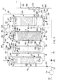
- Reference numeral 70 generally designates a variation of the apparatus of Figure 1 for carrying out the process of the invention.
- a raw water feed line 72 is shown feeding through a pressurising pump 74.
- the feed line 72 branches into flow lines 76 and 78.
- the flow lines 76 and 78 are provided with flow regulation valves 80 and 82 respectively.
- the flow line 76 feeds into a pressure vessel 84 via spray nozzles 77, the vessel 84 being provided with a pressure gauge 86.
- a pressure outlet valve 88 is provided in a gas relief line 89 issuing from the vessel 84.
- the vessel 84 contains packing material 85 supported on a perforated distributor panel 87.
- the vessel 84 has a gas discharge flow line 101 provided with a pressure regulator valve 103.
- a liquid discharge flow line 91 issues from the bottom of the vessel 84 and feeds into another pressure vessel 150 through a liquid distribution manifold 151 which is provided with spray nozzles 153.
- the vessel 150 is except for water in use essentially empty and contains no packing material, but is provided with a sparger 139.
- a carbon dioxide feed line 138 feeds into the sparger 139.
- the vessel 150 is shown having a header space designated by reference numeral 155 in which the manifold 151 is located.
- the vessel 150 is also provided with a pressure gage 152 and a gas discharge flow line 157 issues from the top of the vessel 150, a branch line 93 branching from the line 157.
- the branch line 93 is provided with a flow regulation valve 154 and the flow line 157 is provided with a flow regulation valve 156.
- An acidified feed discharge flow line 92 issues from the vessel 150 and enters the vessel 12 through an optional distribution manifold 94.
- the vessel 12 is essentially identical to the vessel 12 of Figure 2, unless otherwise specified, and the same reference numerals are used to designate the same parts as in Figure 2.
- the vessel 12 is provided with a fines discharge line 141, the line 141 having a flushing valve 143.
- An optional collecting manifold 96 is shown in the header space and discharging from the vessel 12 along flow line 98, which flow line 98 feeds via a pressure/flow regulator 99 into a carbon dioxide vacuum stripping unit 106 through a plurality of spray nozzles 108.
- the unit 106 is provided with a layer of packing material 110 in the form of Pall rings or Raschig rings. Water 112 stripped of gas (CO 2 ) is shown accumulated in the bottom of the unit 106.
- a level controller 114 for controlling the level of the water 112 is shown operatively connected (broken line) to a pump
- a water discharge flow line 117 issues from the lower end of the unit 106 and the flow line 117 is provided with a drain line 120, the drain line 120 having a drain valve 122.
- the flow line 117 feeds through a non-return valve 124 into the pump 116.
- a flow line 119 issues from the pump 116 and , after feeding through a control valve 121, enters the flow line 78 at a blending point 100. From the blending point 100, the flow line 78 feeds into an optional static mixer 102.
- a mixed water flow line 118 issues from the static mixer 102.
- a pH measuring probe (not shown) is provided in the flow line 118.
- An alkali dosing line 126 feeds from an alkali source (not shown) into the flow line 118, downstream from the mixer 102.
- the unit 106 is provided with a vacuum gauge 127.
- a vacuum line 130 issues from the top of the unit 106, the line 130 having a non-return valve 137 and being connected to a blower- or compressor-type vacuum pump 132.
- the line 130 feeds from the pump 132 through a non-return valve 136 and a pressure control valve 131 into the vessel 84 via the sparger 90.
- An air vent line 140 having an air vent control valve 142 branches from the flow line 130 between the non-return valve 136 and the pump 132.
- the line 157 issuing from the vessel 150 feeds through the flow regulating valve 156 into the line 130 at a position 123 between the pump 132 and the non-return valve 137.
- the flow line 101 feeding from the vessel 84 branches into flow lines 109 and 128.
- the flow line 109 is provided with a flow regulation valve 107 and the flow line 128 feeds into a distribution manifold 105 in the unit 106 below the level of the water 112.
- potable raw water typically having a low pH of 4.5 - 6.5, a low calcium content of 2-5 mg/l (as CaCO 3 ) and low alkalinity of 2 - 5 mg/l (as CaCO 3 ) is fed along flow line 72 at a pressure of 200 - 300 KPa through the pump 74, the pump 74 being used to increase the pressure of the water if necessary, into flow lines 76 and 78 respectively.
- Flow, at a pressure eg of approximately 300 KPa, along flow line 76 is controlled by the valve 80, this flow comprising approximately 3 - 5% of the total flow along line 72.
- Flow, at a pressure of eg approximately 250 kPa (ie less than that of the flow along flow line 76) along flow line 78 is controlled by the valve 82, this flow comprising 95- 97% of the total flow along line 72.
- the flow along the flow line 78 may instead be left unrestricted and a pump (not shown) may be provided in the flow line 76 to increase the pressure in the flow line 76 to a value higher than that in the flow in flow line 78, typically 50-100 KPa higher.
- the potable raw water enters the vessel 84 via flow line 76 at its upper end via the spray nozzles 77 and is sprayed on to the packing material 85.
- the water flows downwardly through the packing material 85 before exiting at the bottom of the vessel 84 into flow line 91.
- CO 2 gas (mixed with air recovered from the vessel 106), at a pressure slightly in excess of the pressure in the vessel 84, is fed to the sparger 90 via flow line 130, which CO 2 gas/air mixture rises upwardly through the water in the vessel 84 and dissolves in the water (more specifically in water films which form on the packing material 85 as the water flows downwardly therethrough).
- a counter-current gas mixture/water flow is therefore obtained in the vessel 84.
- co-current operation can be employed if the configuration and layout of the apparatus 70 is altered somewhat, eg the recovered CO 2 can be fed along line 130 directly into the bottom of the vessel 12, allowing dissolution of CO 2 into the water while the CO 2 and water are passing upwardly through the calcium carbonate bed in the vessel 12.
- CO 2 gas is supplied from the CO 2 supply (not shown) and fed into the vessel 150 via the feed line 138 and the sparger 139 until the water issuing from the process reaches a predetermined or desired level of stabilization.
- air is vented to atmosphere through line 93, the venting being controlled by the valve 154.
- Any residual air as well as any undissolved CO 2 remaining after passing up the vessel 84 is discharged from the vessel 84 via feed line 101 through the pressure control valve 103 and is reintroduced into the CO 2 recovery vessel 106 through the distribution manifold 105. Additional CO 2 , as required, is supplied via flow line 138 from the CO 2 supply into the vessel 150.
- the vessel 150 is generally operated such that little or no excess CO 2 accumulates in the header space 155, in the header space 155. If excess CO 2 accumulates in the header space 155, the CO 2 flow into the vessel 150 via line 138 is reduced. Any excess accumulated CO 2 in the header space 155 is fed via flow line 157 back into the flow line 130.
- the acidified water generally having a pH of 4 - 5, containing carbonic acid and dissolved carbon dioxide, passes from the vessel 150 along flow line 92 through the manifold 94 into the bottom of the vessel 12 and passes through the calcium carbonate contained therein.
- the calcium carbonate reacts with the acidified water taking a high concentration of calcium bicarbonate into solution.
- the contact time or retention time of the water in the vessel 12 is typically 5 - 15 minutes.
- the treated water discharged from the vessel 12, after contact typically has a pH of 5.5 - 6.5, a calcium content of 800 - 1000 mg/l (as CaCO 3 ) and an alkalinity of 800 - 1000 mg/l (as CaCO 3 ).
- the treated water has an acidity of 6000 - 9000 mg/l (as CaCO 3 ) and a CaCO 3 dissolution potential of 100 - 300 mg/l. In this state, the water is stable as long as the pH remains below 8.
- Calcium-enriched water passes from the water layer 54 through the manifold 96 into flow line 98 and feeds through the pressure control valve 99 into the unit 106 through the spray nozzles 108.
- the calcium enriched water is sprayed into the unit 106 through the spray nozzles 108, which unit is partially evacuated (100 - 250 mmHg), dissolved CO 2 contained in the water being at least partially stripped from the spray droplets and from such thin films of water as form on the packing material 110 in the unit 106.
- the water accumulates in the lower part of the unit 106 as illustrated at 112 and this water is pumped out to storage through flow line 117 through the non-return valve 124 by means of the pump 116 (through the control valve 121) and enters the flow line 78 at the blending point 100.
- a gravity siphon (not shown) having an approximately 10m minimum fall can be employed to draw water from the unit 106.
- the level controller 114 activates the pump 116 (or a solenoid valve opens if a gravity siphon is employed), thereby to pump water from the unit 106 to keep the water level within preset limits in the unit 106.
- the water discharged from the unit 106 typically has a pH of 6.5 - 8, a calcium content of 800 - 1000 mg/l (as CaCO 3 ), an alkalinity of 800 - 1000 mg/l (as CaCO 3 ), an acidity of 1000 - 3000 mg/l (as CaCO 3 ) and a CaCO 3 precipitation potential of -10 to +500 mg/l.
- the calcium enriched water issues from the vessel 106 along flow line 117 and is pumped by the pump 116 into the flow line 78 containing the main stream at the blending point 100.
- the water is mixed in the static mixer 102 and issues along flow line 118.
- the blended water typically has a pH of 5.5 - 7.0; a calcium content of 30 - 50 mg/l (as CaCO 3 ); an alkalinity of 30 - 50 mg/l (as CaCO 3 ); an acidity of 50 - 100 mg/l (as CaCO 3 ) and a CaCO 3 dissolution potential of 0.5 - 10 mg/l.
- Product water which issues from the mixer 102 is nearly fully stabilised with respect to CaCO 3 and can be fully stabilised (ie zero dissolution potential) or can be adjusted to have a slightly positive precipitation potential, by the addition of a small quantity of alkali (sodium carbonate, calcium hydroxide, or sodium hydroxide) injected directly into the flow line 118 along flow line 126, the dosing being controlled by means of the pH probe.
- alkali sodium carbonate, calcium hydroxide, or sodium hydroxide
- the vacuum pump 132 withdraws CO 2 (and any water vapour and air present) from the unit 106 via line 130 and repressurises the CO 2 upstream of the control valve 131, the CO 2 (and any water vapour and air present) being fed into the vessel 84 through the sparger 90.
- the non-return valve 136 prevents any water from being drawn back into the vacuum pump 132.
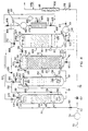
- a flow line 159 replaces the line 130 issuing from the top of the vessel 106 and has a branch line 168.
- the branch line 168 is provided with a discharge valve 170.
- the flow line 157 from vessel 150 feeds through a non-return valve 158 into a compressor-type vacuum pump 160.
- the flow line 159 feeds into the flow line 157 at a point between the non-return valve 158 and the pump 160.
- a flow line 172 issues from the pump 160 into a membrane gas separation unit 161.
- An air/water vapour flow line 162 issues from the unit 161 through a pressure control valve 163 and feeds into the flow line 101, before the flow line 101 feeds into the distribution manifold 105 in the unit 106.
- a CO 2 flow line 165 issues from the unit 161 and feeds into a compressor-type vacuum pump 166 (which is of smaller capacity than the pump 160 and feeds into the line 130 in the fashion of pump 132 of Figure 3).
- the flow line 130 issues from the pump 166, which flow line 130 then feeds into the sparger 90 via the non-return valve 136 and the control valve 131.
- the flow line 101 can feed into the flow line 157 between the valve 158 and the pump 160.
- the process of the present invention when carried out with the apparatus 70 of Figure 4, is essentially similar to that described above with reference to Figure 3, the primary difference being that the vacuum pump 160 withdraws a gas mixture containing CO 2 stripped from the calcium enriched water in the unit 106 via the flow line 159, thereby creating a partial vacuum in the unit 106.
- the pump 160 recompresses the gas mixture (CO 2 , air and water vapour) to a pressure of approximately 200 - 300 KPa before pumping the gas mixture into the membrane gas separation unit 161.
- CO 2 is separated from the gas mixture and is fed via flow line 165 into the pump 166.
- at least partially purified CO 2 issues from the unit 161 via feed line 165.
- the CO 2 issues from the unit 161 at a lower pressure than the remainder of the gas mixture which issues from the unit 161 along flow line 162.
- the membrane allows CO 2 to pass therethrough while substantially preventing passage of other gases, e.g. nitrogen and/or oxygen, thereby separating the CO 2 from the other gases and water vapour being fed, together with the CO 2 , into the unit 161.
- CO 2 recovered from the unit 161 is returned via the flow line 130 back into the vessel 84 to acidify the water entering the vessel 84.
- the remainder of the gas mixture from which the CO 2 is separated passes through the unit 161 and, as mentioned above, issues via line 162 therefrom before passing through the pressure control valve 163, being then fed with the contents of flow line 101 into flow line 128 and then via the distribution manifold 105 into the unit 106.
- the gas mixture circulating in this manner assists with the stripping of the CO 2 from the water passing through the unit 106. If excess CO 2 accumulates in the header space 155 of the vessel 150, it is fed along flow line 157 into flow line 159 before entering the pump 160.
- the membrane unit 161 can be replaced with a pressure swing adsorption (PSA) unit (not shown).
- PSD pressure swing adsorption
- the pressure swing adsorption unit can include two or more activated carbon containers.
- the containers are successively used by allowing the gas mixture (CO 2 , air and water vapour) to flow through one of the containers charged to a pressure of 300 - 400 KPa while the other container or containers undergo discharging.
- the container being discharged is depressurised, venting any CO 2 adsorbed on the activated carbon into the line 130 thus acidifying the water in the vessel 84 as described above, while the gas mixture is passed through the next container under pressure, allowing the CO 2 in the gas mixture to be adsorbed on the carbon.
- Pressurised operation and water recirculation both promote increased limestone consumption/dissolution rates and provision is made for flushing of insoluble fines to waste.
- Excess carbon dioxide used to promote the rapid dissolution of the calcium carbonate particles can be recovered and reused in the process, thereby reducing process costs.
- the use of limestone in the process in accordance with the invention is preferred as limestone is generally inexpensive compared to lime (calcium hydroxide) thereby further reducing process costs.
- the invention is believed to provide a practically feasible and economically attractive process, using straightforward apparatus, for upgrading waters, eg for municipal, agricultural and/or industrial use, which is stabilized to have reduced aggressiveness to cementitious structures and reduced corrosiveness to metal structures.
Landscapes
- Chemical & Material Sciences (AREA)
- Environmental & Geological Engineering (AREA)
- General Chemical & Material Sciences (AREA)
- Life Sciences & Earth Sciences (AREA)
- Hydrology & Water Resources (AREA)
- Engineering & Computer Science (AREA)
- Water Supply & Treatment (AREA)
- Organic Chemistry (AREA)
- Chemical Kinetics & Catalysis (AREA)
- Physical Water Treatments (AREA)
- Mechanical Treatment Of Semiconductor (AREA)
- Removal Of Specific Substances (AREA)
- Furan Compounds (AREA)
- Sorption Type Refrigeration Machines (AREA)
- Treatment Of Water By Ion Exchange (AREA)
- Agricultural Chemicals And Associated Chemicals (AREA)
- Pharmaceuticals Containing Other Organic And Inorganic Compounds (AREA)
- Organic Low-Molecular-Weight Compounds And Preparation Thereof (AREA)
- Water Treatment By Electricity Or Magnetism (AREA)
- Disintegrating Or Milling (AREA)
- Fertilizers (AREA)
Claims (12)
- Verfahren zur Stabilisierung von Rohwasser mit einem pH-Wert von 2,5 bis 9, einer Alkalität von höchstens 150 mg/ℓ, ausgedrückt als Calciumcarbonat, einem Calciumgehalt von höchstens 100 mg/ℓ, ausgedrückt als Calciumcarbonat, und einem positiven Calciumcarbonat-Lösungspotential, welches dasumfaßt.Trennen eines Teils des Wasser vom Rest und Ansäuern dieses Teils, um dessen Calciumcarbonat-Lösungspotential zu erhöhen,Leiten des angesäuerten Wassers durch eine Calciumcarbonat enthaltende Partikelschüttung, worin dieses Wasser einen Teil des Calciumcarbonats der Körner verbraucht, bevor es aus dem Bett strömt, wobei der Verbrauch mit einer Vergrößerung des Calciumgehalts des Wassers und mit einer Erhöhung der Alkalität des Wassers, wenn es durch das Bett strömt, einhergeht, undVermischen des aus dem Bett kommenden Wassers mit dem Rest des Rohwassers, wodurch ein wenigstens teilweise stabilisiertes Produktwasser mit einem positiven Calciumcarbonat-Lösungspotential, das mindestens um 2 mg/ℓ Calciumcarbonat kleiner als das des Rohwassers ist, erhalten wird,
- Verfahren nach Anspruch 1, worin ausreichend Calciumcarbonat von den Körnern verbraucht wird, um ein Produktwasser mit einem Calciumcarbonat-Lösungspotential von zwischen
-100 mg/ℓ und +600 mg/ℓ Calciumcarbonat zu erhalten. - Verfahren nach Anspruch 1 oder 2, worin ausreichend Calciumcarbonat von den Körnern verbraucht wird, um ein Produktwasser mit einem positiven Fällungspotential von 0 bis 5 mg/ℓ Calciumcarbonat im Wasser zu erhalten, wodurch das Wasser vollständig stabilisiert ist.
- Verfahren nach einem der vorhergehenden Ansprüche, worin das Wasser, welches durch das Bett geschickt wird, darin einem Druck von 100 bis 300 kPa ausgesetzt ist.
- Verfahren nach einem der vorhergehenden Ansprüche, welches das Ansäuern des Teils des Rohwassers, bevor er durch das Bett strömen gelassen wird, umfaßt, wobei man das Calciumcarbonat-Lösungspotential des Wassers durch die Ansäuerung ausreichend erhöht, damit das Wasser, welches durch das Bett geschickt wird, mit einem pH-Wert von = 6 hineingelangt.
- Verfahren nach Anspruch 5, worin man das Ansäuern durchführt, indem Kohlendioxid mit einem Druck von 100 bis 300 kPa in den Teil des Wassers geleitet wird, wobei der angesäuerte Teil des Wassers aufsteigend durch die Partikelschüttung geschickt wird.
- Verfahren nach einem der vorhergehenden Ansprüche, welches die Rezirkulation eines Teils des vom Bett kommenden Wassers zum Bett umfaßt, wodurch der Wasserdurchfluß durch das Bett, bezogen auf den Nettodurchfluß an Rohwasser zum Bett, erhöht wird.
- Verfahren nach Anspruch 7, worin das Verhältnis von Durchfluß des rezirkulierten Wassers zu Nettodurchfluß an Rohwasser zum Bett 1 : 1 bis 20 : 1 beträgt.
- Verfahren nach einem der vorhergehenden Ansprüche, welches das Austreiben von CO2 aus dem vom Bett kommenden Wasser umfaßt, wobei das Austreiben bis zu einem solchen Grade erfolgt, daß die im Produktwasser gelöst bleibende CO2-Menge die CO2-Menge, welche im im Gleichgewicht mit der Atmosphäre befindlichen Wasser gelöst ist, um nicht mehr als 5 % übersteigt.
- Verfahren nach Anspruch 9, worin das Austreiben durchgeführt wird, bevor das aus dem Bett kommende Wasser mit dem Rest an Rohwasser vermischt wird, wobei das Austreiben zwischen einer Kaskade und dem Versprühen des Wassers in einem geschlossenen Behälter mit einem Druck von -6,7 bis -20 kPa ausgewählt wird und das Verfahren ferner umfaßt, das aus diesem Wasser wenigstens teilweise ausgetriebene gasförmige CO2 zum Ansäuern des Teils des Rohwassers, der durch das Bett aus Calciumcarbonatkörnern geleitet wird, bevor dieser Teil das Bett passiert, einzusetzen.
- Verfahren nach einem der vorhergehenden Ansprüche, welches als letzte Verfahrensstufe die Einstellung des Produktwassers mit Alkali umfaßt, um den gewünschten Grad der Stabilisierung zu erhalten, wobei die Zudosierung des Alkalis so erfolgt, daß ein positives Calciumcarbonat-Fällungspotential und ein pH-Wert des eingestellten Wassers von 8 bis 9,5 erreicht wird.
- Verfahren nach einem der vorhergehenden Ansprüche, worin das Wasser mit einer solchen Strömungsgeschwindigkeit durch das Bett strömt, daß die mittlere Verweilzeit des durch das Bett geschickten Wassers 1 bis 30 Minuten im Bett beträgt.
Applications Claiming Priority (3)
| Application Number | Priority Date | Filing Date | Title |
|---|---|---|---|
| ZA953309 | 1995-04-24 | ||
| ZA9503309 | 1995-04-24 | ||
| PCT/NL1996/000167 WO1996033952A1 (en) | 1995-04-24 | 1996-04-18 | Stabilization of water |
Publications (2)
| Publication Number | Publication Date |
|---|---|
| EP0822923A1 EP0822923A1 (de) | 1998-02-11 |
| EP0822923B1 true EP0822923B1 (de) | 1999-06-30 |
Family
ID=25585032
Family Applications (1)
| Application Number | Title | Priority Date | Filing Date |
|---|---|---|---|
| EP96911103A Revoked EP0822923B1 (de) | 1995-04-24 | 1996-04-18 | Stabilisierung von wasser |
Country Status (10)
| Country | Link |
|---|---|
| US (1) | US5993737A (de) |
| EP (1) | EP0822923B1 (de) |
| AT (1) | ATE181716T1 (de) |
| AU (1) | AU695204B2 (de) |
| BR (1) | BR9608190A (de) |
| CA (1) | CA2218882A1 (de) |
| DE (1) | DE69603074T2 (de) |
| ES (1) | ES2132911T3 (de) |
| NZ (1) | NZ305946A (de) |
| WO (1) | WO1996033952A1 (de) |
Families Citing this family (16)
| Publication number | Priority date | Publication date | Assignee | Title |
|---|---|---|---|---|
| DE10020437A1 (de) * | 2000-04-26 | 2001-11-08 | Honeywell Ag | Verfahren und Vorrichtung zur Verminderung von Steinbildung und/oder Korrosion in Systemen, die Flüssigkeiten führen oder mit Flüssigkeiten in Kontakt stehen |
| FR2823499B1 (fr) * | 2001-04-12 | 2004-02-27 | Vivendi Water Systems | Procede de remineralisation d'une eau brute |
| US20090099054A1 (en) * | 2007-05-04 | 2009-04-16 | Ecolab Inc. | Method for formulating a reduced phosphorus branded cleaning product or cleaning system |
| US7960329B2 (en) | 2007-05-04 | 2011-06-14 | Ecolab Usa Inc. | Compositions including magnesium ion, calcium ion, and silicate and methods employing them to reduce corrosion and etch |
| US20090082245A1 (en) * | 2007-05-04 | 2009-03-26 | Ecolab Inc. | Method for formulating a branded cleaning product |
| DE102007035253A1 (de) * | 2007-07-27 | 2009-01-29 | Anton Hausberger | Vorrichtung zum Dispergieren eines Feststoffs in Abwasser |
| DE102008060310B4 (de) * | 2008-12-03 | 2013-01-31 | Dge Dr.-Ing. Günther Engineering Gmbh | Verfahren und Anlage zur Reinigung von Roh- oder Biogas zur Gewinnung von Methan |
| US7771599B1 (en) * | 2009-03-09 | 2010-08-10 | Doosan Hydro Technology, Inc. | System and method for using carbon dioxide sequestered from seawater in the remineralization of process water |
| SI2418177T1 (sl) * | 2010-08-13 | 2015-03-31 | Omya International Ag | MIKRONIZIRAN CaCO3 INJEKCIJSKI SISTEM GOŠČE ZA REMINERALIZACIJO RAZSOLJENE IN SVEŽE VODE |
| US20140014582A1 (en) * | 2011-02-23 | 2014-01-16 | Miguel Ramon Muro | Fluid remineralization method |
| PT2548848E (pt) * | 2011-07-22 | 2015-06-22 | Omya Int Ag | Sistema de injeção de suspensão espessa de caco3 micronizado para a remineralização de água dessalinizada e fresca |
| ES2525646B1 (es) * | 2012-02-22 | 2015-11-10 | Abengoa Water, S.L. | Procedimiento de remineralización de fluidos |
| GB2499992B (en) * | 2012-03-05 | 2014-12-10 | Ide Technologies Ltd | Water mineralization |
| PL3091862T3 (pl) * | 2013-12-18 | 2021-06-14 | Société des Produits Nestlé S.A. | Sposób dostarczania napoju na bazie wody wzbogaconego w magnez i/albo wapń |
| EP3181521A1 (de) * | 2015-12-16 | 2017-06-21 | Nestec S.A. | Gereinigtes und remineralisiertes wasser |
| EP3428128A1 (de) * | 2017-07-12 | 2019-01-16 | Omya International AG | Verfahren zur erhöhung der magnesium-ionen-konzentration in speisewasser |
Family Cites Families (19)
| Publication number | Priority date | Publication date | Assignee | Title |
|---|---|---|---|---|
| DE1904410C3 (de) * | 1969-01-30 | 1978-07-06 | Arno Dr. 7500 Karlsruhe Friske | Verfahren zur Vermeidung der Überalkalisierung bei der Entsäuerung von Trink- und Brauchwasser |
| US3839199A (en) * | 1972-04-14 | 1974-10-01 | Permutit Co Inc | Method of softening water to provide easily drained and easily filtered precipitates |
| US4153556A (en) * | 1977-12-28 | 1979-05-08 | Uop Inc. | Method and apparatus for conditioning demineralized water |
| US4188291A (en) * | 1978-04-06 | 1980-02-12 | Anderson Donald R | Treatment of industrial waste water |
| SU715493A1 (ru) * | 1978-07-12 | 1980-02-15 | Предприятие П/Я М-5371 | Способ минерализации опресненной воды |
| JPS5916591A (ja) * | 1982-07-17 | 1984-01-27 | Ryoichi Yamada | 石灰石による酸性水の中和方法 |
| SE447819B (sv) * | 1983-09-16 | 1986-12-15 | Ifoe Sanitaer Ab | Anordning for neutralisering av forsurat vatten |
| CA1246250A (en) * | 1984-09-19 | 1988-12-06 | Ulo Psabo | Apparatus for neutralizing acidified water |
| JPH0630757B2 (ja) * | 1985-03-25 | 1994-04-27 | 株式会社ササクラ | 水質監視方法及び水質制御方法 |
| SU1412232A1 (ru) * | 1986-03-06 | 1990-09-15 | Предприятие П/Я М-5371 | Способ приготовлени питьевой воды |
| JP2539795B2 (ja) * | 1986-08-05 | 1996-10-02 | 日揮株式会社 | 海水から飲料水を得る方法 |
| JPS6391194A (ja) * | 1986-10-02 | 1988-04-21 | Sasakura Eng Co Ltd | 純水からミネラル化水の製造方法 |
| US4814074A (en) * | 1987-03-03 | 1989-03-21 | Hydroflo, Inc. | Water neutralizer |
| JP2673237B2 (ja) * | 1988-08-12 | 1997-11-05 | 清水建設株式会社 | 電気分解と中和による健康飲用水の製造方法及びその製造装置 |
| WO1991004949A1 (en) * | 1989-09-26 | 1991-04-18 | Commonwealth Scientific And Industrial Research Organisation | Water purification process |
| AU639192B2 (en) * | 1990-07-20 | 1993-07-15 | Csir | Treatment of water |
| US5174901A (en) * | 1991-06-10 | 1992-12-29 | Smith Verity C | Liquid purifying system |
| ZA945602B (en) * | 1993-07-30 | 1995-03-06 | Csir | Stabilization of water |
| DE4431911A1 (de) * | 1994-09-08 | 1996-03-14 | Passavant Werke | Verfahren zum Aufbereiten von weichen Wässern zu Trinkwasser |
-
1996
- 1996-04-18 AU AU54086/96A patent/AU695204B2/en not_active Ceased
- 1996-04-18 CA CA002218882A patent/CA2218882A1/en not_active Abandoned
- 1996-04-18 AT AT96911103T patent/ATE181716T1/de not_active IP Right Cessation
- 1996-04-18 EP EP96911103A patent/EP0822923B1/de not_active Revoked
- 1996-04-18 BR BR9608190A patent/BR9608190A/pt not_active IP Right Cessation
- 1996-04-18 NZ NZ305946A patent/NZ305946A/xx unknown
- 1996-04-18 WO PCT/NL1996/000167 patent/WO1996033952A1/en not_active Ceased
- 1996-04-18 DE DE69603074T patent/DE69603074T2/de not_active Expired - Fee Related
- 1996-04-18 US US08/945,643 patent/US5993737A/en not_active Expired - Fee Related
- 1996-04-18 ES ES96911103T patent/ES2132911T3/es not_active Expired - Lifetime
Also Published As
| Publication number | Publication date |
|---|---|
| CA2218882A1 (en) | 1996-10-31 |
| NZ305946A (en) | 1999-01-28 |
| AU5408696A (en) | 1996-11-18 |
| AU695204B2 (en) | 1998-08-06 |
| US5993737A (en) | 1999-11-30 |
| EP0822923A1 (de) | 1998-02-11 |
| DE69603074T2 (de) | 1999-11-18 |
| DE69603074D1 (de) | 1999-08-05 |
| ES2132911T3 (es) | 1999-08-16 |
| BR9608190A (pt) | 1999-05-04 |
| ATE181716T1 (de) | 1999-07-15 |
| WO1996033952A1 (en) | 1996-10-31 |
Similar Documents
| Publication | Publication Date | Title |
|---|---|---|
| US5993737A (en) | Stabilization of water | |
| US5702594A (en) | Apparatus for treatment of waste water and/or exhaust gases containing fluorine and surface active agents | |
| US4614596A (en) | Apparatus and method for dissolving a gas in an aqueous stream | |
| US5167806A (en) | Gas dissolving and releasing liquid treatment system | |
| US4469599A (en) | Apparatus and method for denitrifying water | |
| US6056876A (en) | Method and apparatus for wastewater treatment | |
| US4043771A (en) | Method of and apparatus for the dissolution of gases in liquids | |
| US7288191B2 (en) | Sludge treatment apparatus | |
| CA2066466A1 (en) | Method and apparatus for processing manure | |
| JP2001507619A (ja) | 廃水の生物学的精製用装置 | |
| US3477947A (en) | Method and apparatus for treating waste materials | |
| US4442005A (en) | Method of and apparatus for the biological decontamination of waste water | |
| MXPA97004825A (en) | Method and apparatus for the treatment of residual waters concentra | |
| CA2208847A1 (en) | Method and apparatus for the treatment of concentrated wastewater | |
| US4190539A (en) | Apparatus for on-site renovation of sanitary waters | |
| US4324657A (en) | Apparatus for the treatment of liquids | |
| CA1081378A (en) | Continuous fermentation process and apparatus | |
| US4599168A (en) | Apparatus for treatment of waste water having selective recycle control | |
| US7060186B2 (en) | Method and apparatus for the treatment of wastewater | |
| JP4080046B2 (ja) | 嫌気性処理方法および装置 | |
| US20030098277A1 (en) | Sweetening of mixed liquor during solid-liquid separation | |
| KR101931562B1 (ko) | 잔류산소 재순환관을 구비한 산소용해장치 | |
| JP2698310B2 (ja) | 廃水の嫌気性処理装置とその運転方法 | |
| SK283898B6 (sk) | Spôsob odstraňovania plynnej elementárnej ortuti z plynu a zariadenie na vykonávanie tohto spôsobu | |
| US4587019A (en) | Aerobic digestion of sludge |
Legal Events
| Date | Code | Title | Description |
|---|---|---|---|
| PUAI | Public reference made under article 153(3) epc to a published international application that has entered the european phase |
Free format text: ORIGINAL CODE: 0009012 |
|
| 17P | Request for examination filed |
Effective date: 19971031 |
|
| AK | Designated contracting states |
Kind code of ref document: A1 Designated state(s): AT BE CH DE DK ES FI FR GB GR IE IT LI LU MC NL PT SE |
|
| AX | Request for extension of the european patent |
Free format text: AL PAYMENT 971031;LT PAYMENT 971031;LV PAYMENT 971031;SI PAYMENT 971031 |
|
| GRAG | Despatch of communication of intention to grant |
Free format text: ORIGINAL CODE: EPIDOS AGRA |
|
| 17Q | First examination report despatched |
Effective date: 19980707 |
|
| GRAG | Despatch of communication of intention to grant |
Free format text: ORIGINAL CODE: EPIDOS AGRA |
|
| GRAH | Despatch of communication of intention to grant a patent |
Free format text: ORIGINAL CODE: EPIDOS IGRA |
|
| GRAH | Despatch of communication of intention to grant a patent |
Free format text: ORIGINAL CODE: EPIDOS IGRA |
|
| RAP1 | Party data changed (applicant data changed or rights of an application transferred) |
Owner name: IMPLICO B.V. |
|
| GRAA | (expected) grant |
Free format text: ORIGINAL CODE: 0009210 |
|
| AK | Designated contracting states |
Kind code of ref document: B1 Designated state(s): AT BE CH DE DK ES FI FR GB GR IE IT LI LU MC NL PT SE |
|
| AX | Request for extension of the european patent |
Free format text: AL PAYMENT 19971031;LT PAYMENT 19971031;LV PAYMENT 19971031;SI PAYMENT 19971031 |
|
| LTIE | Lt: invalidation of european patent or patent extension | ||
| PG25 | Lapsed in a contracting state [announced via postgrant information from national office to epo] |
Ref country code: NL Free format text: LAPSE BECAUSE OF FAILURE TO SUBMIT A TRANSLATION OF THE DESCRIPTION OR TO PAY THE FEE WITHIN THE PRESCRIBED TIME-LIMIT Effective date: 19990630 Ref country code: IT Free format text: LAPSE BECAUSE OF FAILURE TO SUBMIT A TRANSLATION OF THE DESCRIPTION OR TO PAY THE FEE WITHIN THE PRE;WARNING: LAPSES OF ITALIAN PATENTS WITH EFFECTIVE DATE BEFORE 2007 MAY HAVE OCCURRED AT ANY TIME BEFORE 2007. THE CORRECT EFFECTIVE DATE MAY BE DIFFERENT FROM THE ONE RECORDED.SCRIBED TIME-LIMIT Effective date: 19990630 Ref country code: FI Free format text: LAPSE BECAUSE OF NON-PAYMENT OF DUE FEES Effective date: 19990630 Ref country code: BE Free format text: LAPSE BECAUSE OF FAILURE TO SUBMIT A TRANSLATION OF THE DESCRIPTION OR TO PAY THE FEE WITHIN THE PRESCRIBED TIME-LIMIT Effective date: 19990630 |
|
| REF | Corresponds to: |
Ref document number: 181716 Country of ref document: AT Date of ref document: 19990715 Kind code of ref document: T |
|
| REG | Reference to a national code |
Ref country code: CH Ref legal event code: NV Representative=s name: PATENTANWAELTE SCHAAD, BALASS, MENZL & PARTNER AG Ref country code: CH Ref legal event code: EP |
|
| ET | Fr: translation filed | ||
| REF | Corresponds to: |
Ref document number: 69603074 Country of ref document: DE Date of ref document: 19990805 |
|
| REG | Reference to a national code |
Ref country code: ES Ref legal event code: FG2A Ref document number: 2132911 Country of ref document: ES Kind code of ref document: T3 |
|
| REG | Reference to a national code |
Ref country code: IE Ref legal event code: FG4D |
|
| PG25 | Lapsed in a contracting state [announced via postgrant information from national office to epo] |
Ref country code: PT Free format text: LAPSE BECAUSE OF FAILURE TO SUBMIT A TRANSLATION OF THE DESCRIPTION OR TO PAY THE FEE WITHIN THE PRESCRIBED TIME-LIMIT Effective date: 19990930 Ref country code: DK Free format text: LAPSE BECAUSE OF FAILURE TO SUBMIT A TRANSLATION OF THE DESCRIPTION OR TO PAY THE FEE WITHIN THE PRESCRIBED TIME-LIMIT Effective date: 19990930 |
|
| PG25 | Lapsed in a contracting state [announced via postgrant information from national office to epo] |
Ref country code: GR Free format text: LAPSE BECAUSE OF FAILURE TO SUBMIT A TRANSLATION OF THE DESCRIPTION OR TO PAY THE FEE WITHIN THE PRESCRIBED TIME-LIMIT Effective date: 19991001 |
|
| NLV1 | Nl: lapsed or annulled due to failure to fulfill the requirements of art. 29p and 29m of the patents act | ||
| PLBQ | Unpublished change to opponent data |
Free format text: ORIGINAL CODE: EPIDOS OPPO |
|
| PGFP | Annual fee paid to national office [announced via postgrant information from national office to epo] |
Ref country code: SE Payment date: 20000406 Year of fee payment: 5 |
|
| PLBI | Opposition filed |
Free format text: ORIGINAL CODE: 0009260 |
|
| PG25 | Lapsed in a contracting state [announced via postgrant information from national office to epo] |
Ref country code: LU Free format text: LAPSE BECAUSE OF NON-PAYMENT OF DUE FEES Effective date: 20000418 Ref country code: IE Free format text: LAPSE BECAUSE OF NON-PAYMENT OF DUE FEES Effective date: 20000418 |
|
| PLBF | Reply of patent proprietor to notice(s) of opposition |
Free format text: ORIGINAL CODE: EPIDOS OBSO |
|
| 26 | Opposition filed |
Opponent name: RHEINKALK AKDOLIT GMBH Effective date: 20000330 |
|
| PLBF | Reply of patent proprietor to notice(s) of opposition |
Free format text: ORIGINAL CODE: EPIDOS OBSO |
|
| PG25 | Lapsed in a contracting state [announced via postgrant information from national office to epo] |
Ref country code: MC Free format text: LAPSE BECAUSE OF NON-PAYMENT OF DUE FEES Effective date: 20001031 |
|
| PLBF | Reply of patent proprietor to notice(s) of opposition |
Free format text: ORIGINAL CODE: EPIDOS OBSO |
|
| REG | Reference to a national code |
Ref country code: IE Ref legal event code: MM4A |
|
| PGFP | Annual fee paid to national office [announced via postgrant information from national office to epo] |
Ref country code: FR Payment date: 20010412 Year of fee payment: 6 |
|
| PGFP | Annual fee paid to national office [announced via postgrant information from national office to epo] |
Ref country code: ES Payment date: 20010417 Year of fee payment: 6 |
|
| PGFP | Annual fee paid to national office [announced via postgrant information from national office to epo] |
Ref country code: GB Payment date: 20010418 Year of fee payment: 6 |
|
| PG25 | Lapsed in a contracting state [announced via postgrant information from national office to epo] |
Ref country code: SE Free format text: LAPSE BECAUSE OF NON-PAYMENT OF DUE FEES Effective date: 20010419 |
|
| PGFP | Annual fee paid to national office [announced via postgrant information from national office to epo] |
Ref country code: CH Payment date: 20010427 Year of fee payment: 6 |
|
| PGFP | Annual fee paid to national office [announced via postgrant information from national office to epo] |
Ref country code: AT Payment date: 20010430 Year of fee payment: 6 |
|
| PGFP | Annual fee paid to national office [announced via postgrant information from national office to epo] |
Ref country code: DE Payment date: 20010627 Year of fee payment: 6 |
|
| RDAH | Patent revoked |
Free format text: ORIGINAL CODE: EPIDOS REVO |
|
| EUG | Se: european patent has lapsed |
Ref document number: 96911103.8 |
|
| RDAG | Patent revoked |
Free format text: ORIGINAL CODE: 0009271 |
|
| STAA | Information on the status of an ep patent application or granted ep patent |
Free format text: STATUS: PATENT REVOKED |
|
| REG | Reference to a national code |
Ref country code: CH Ref legal event code: PL |
|
| 27W | Patent revoked |
Effective date: 20011122 |
|
| GBPR | Gb: patent revoked under art. 102 of the ep convention designating the uk as contracting state |
Free format text: 20011122 |