EP0823033B1 - Drehkupplung - Google Patents
Drehkupplung Download PDFInfo
- Publication number
- EP0823033B1 EP0823033B1 EP96914163A EP96914163A EP0823033B1 EP 0823033 B1 EP0823033 B1 EP 0823033B1 EP 96914163 A EP96914163 A EP 96914163A EP 96914163 A EP96914163 A EP 96914163A EP 0823033 B1 EP0823033 B1 EP 0823033B1
- Authority
- EP
- European Patent Office
- Prior art keywords
- rotating joint
- joint according
- receiving member
- casing
- insertion member
- Prior art date
- Legal status (The legal status is an assumption and is not a legal conclusion. Google has not performed a legal analysis and makes no representation as to the accuracy of the status listed.)
- Expired - Lifetime
Links
Images

Classifications
-
- F—MECHANICAL ENGINEERING; LIGHTING; HEATING; WEAPONS; BLASTING
- F16—ENGINEERING ELEMENTS AND UNITS; GENERAL MEASURES FOR PRODUCING AND MAINTAINING EFFECTIVE FUNCTIONING OF MACHINES OR INSTALLATIONS; THERMAL INSULATION IN GENERAL
- F16L—PIPES; JOINTS OR FITTINGS FOR PIPES; SUPPORTS FOR PIPES, CABLES OR PROTECTIVE TUBING; MEANS FOR THERMAL INSULATION IN GENERAL
- F16L27/00—Adjustable joints; Joints allowing movement
- F16L27/08—Adjustable joints; Joints allowing movement allowing adjustment or movement only about the axis of one pipe
- F16L27/0804—Adjustable joints; Joints allowing movement allowing adjustment or movement only about the axis of one pipe the fluid passing axially from one joint element to another
- F16L27/0808—Adjustable joints; Joints allowing movement allowing adjustment or movement only about the axis of one pipe the fluid passing axially from one joint element to another the joint elements extending coaxially for some distance from their point of separation
- F16L27/0824—Adjustable joints; Joints allowing movement allowing adjustment or movement only about the axis of one pipe the fluid passing axially from one joint element to another the joint elements extending coaxially for some distance from their point of separation with ball or roller bearings
-
- F—MECHANICAL ENGINEERING; LIGHTING; HEATING; WEAPONS; BLASTING
- F16—ENGINEERING ELEMENTS AND UNITS; GENERAL MEASURES FOR PRODUCING AND MAINTAINING EFFECTIVE FUNCTIONING OF MACHINES OR INSTALLATIONS; THERMAL INSULATION IN GENERAL
- F16C—SHAFTS; FLEXIBLE SHAFTS; ELEMENTS OR CRANKSHAFT MECHANISMS; ROTARY BODIES OTHER THAN GEARING ELEMENTS; BEARINGS
- F16C2361/00—Apparatus or articles in engineering in general
Definitions
- the invention relates to a rotary coupling for pressure lines according to the preamble of claim 1.
- a simple hose for example a Water hose
- the jacket of which is made of elastic material is not particularly sensitive to turns in the coat.
- Hoses from media under high pressure flow through, but are usually enveloping Surround metal hose. With such pressure hoses can twisted turns easily to destroy the casing to lead. It is therefore particularly advisable for pressure hoses connect them to pipes via rotating couplings.
- a simple form of rotating hose fitting for Pressure hoses are known from DE OS 27 11 584.
- the handheld device is not transferred to the hose
- the grommet with a guide lug that fits in one Screw approach is rotatably mounted.
- the leadership approach is sealed with an O-ring.
- This form of rotatable hose fitting only holds high pressures conditionally stood and is therefore unsuitable for use.
- the rotary connection fails by means of the Plain bearing if there is a passage of hot media different expansion of the individual components, because the friction in the plain bearing increases.
- From DE-OS 14 75 684 is a slewing ring for Liquid lines with a stationary and one around it rotatable or pivotable connector known in the one Rolling bearing between the parts, the low-friction turning guaranteed.
- This slewing ring is especially for this suitable, pressurized lubricants quickly to feed rotating shafts. To ensure safe rotation ensure the rotating shaft is through a double row angular contact ball bearing and a bore.
- the Assembly of the individual components and their exact alignment is very expensive. Because the hollow pin of the connector can be relatively long and of small diameter the heat from the passage of hot media, in particular from Steam is poorly discharged. The components stretch to different degrees and jam. For the safe Coupling of steam pressure hoses is this slewing ring therefore not suitable.
- the object of the invention is an easy to assemble and working reliably under extreme conditions To create a rotating coupling with a steam in particular flowed through pressure hose rotatable to a line can be connected.
- the rotating coupling ensures easy installation of the pressure hose than no longer on the orientation of the individual components must be respected against each other. At the same time, a different expansion has an effect the components are not disadvantageous in the event of uneven heating on the function of the rotary coupling. It can also be in an advantageous embodiment on the use of Ball cages can be dispensed with.
- the rotary coupling is advantageously used as a connection fitting between steam, hot water hoses and / or Spray lances or between the fixed connection and the Hose inserted.
- the plug-in part is in a special Embodiment a casting that is on its surface Has formations.
- these forms are advantageous than the uniform achieved with it Wall thickness of the plug part to its uniform Expansion when heated contributes, so that jamming in leadership is avoided.
- the formations enlarge the Surface so that good heat dissipation is guaranteed.
- the formations also help to save material.
- the rotary coupling is therefore particularly suitable for hoses couple the steam at high temperatures and pressures to lead.
- the rotary coupling ensures a safe Connection of pressure hoses made of steam with 18 bar and of 210 ° C. It fulfills the requirements of the German industry standard for steam hoses and their Fittings (DIN 2825 and DIN 2826) requirements.
- a particular advantage of the rotary coupling is that failure of the elastic bearing the compressive strength and tightness is maintained because the plug-in part on the Edge of the housing comes to rest and not from the Receiving part slips.
- the strength of the Swivel coupling ensures and a burst of the connection locked out.
- the room serves between the assembled parts and the housing as Pressure chamber, which is not absolutely tight but mechanical remains tightly closed.
- the housing is designed so that the pressure chamber of the load that arises in the event of a leak withstands. The steam and condenses in this pressure chamber occurs as water on the side facing away from the user out.
- Rotary coupling becomes extremely hot Rotary coupling in an advantageous embodiment provide protection against accidental contact. Through the contact protection is safe handling of the rotating coupling at all times possible. To heat transfer and thus the heating of the To reduce contact protection, it is advantageous to use it to be welded to the receiving part on a small contact surface.
- the rotary coupling according to the invention is also distinguished characterized in that in the event of destruction of the inner, between the receiving part and the plug-in part arranged seal the medium is not or only to a very small extent the rotating coupling can escape. The exit is through an additional seal between the plug and the Prevention of the rotating coupling housing.
- the rotary coupling according to the invention ensures under tightness, component strength and extreme conditions Rotatability.
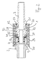
- a rotary coupling is shown by which a plug-in part 1 with a receiving part 2 rotatable connected is. Both plug-in part 1 and receiving part 2 are rotationally symmetrical and each have a bore 5 and 6 on the same in diameter. Between the Receiving part 2 and the plug-in part are two angular contact ball bearings K1 and K2 attached.
- the plug-in part 1 is provided with a hose nozzle 3 which a pressure hose, not shown, can be pushed on and in particular with pairs of clamping shells, not shown is fixable.
- the plug-in part 1 is at its grommet 3 opposite side formed into a hollow pin 4, which in a bore 7 of the receiving part protrudes. In the hole 7 grooves 8 are screwed in to accommodate sealing rings 9 serve.
- the plug-in part 1 is thus tight and rotatable in the Recording part 2 performed.
- the receiving part 2 is for connection provided on fittings with a standardized thread 24.
- the plug-in part 1 and the receiving part 2 are in the assembled Condition surrounded by a housing 10.
- the housing 10 is with one side over a cylindrical nozzle 11 of the Receiving part 2 pushed or screwed on and closes with a projection 12 integrally formed thereon.
- the inner one Edge of the housing 10 is provided with a thread 13 which the housing 10 is screwed onto the socket 11. With its other side, the housing 10 takes the plug part 1 with the storage and holds the plug 1 on Recording part 2.
- a sealing ring groove 16 is introduced, in which a Sealing ring 9 is located. This seal between the receiving part 2 and plug-in part 1 prevents the escape of Lubricant and at the same time the penetration of dirt.
- the plug part 1 is within the housing 10 with the two Angular contact ball bearings K1 and K2 rotatably mounted. It serves it as an inner ring for both bearings at the same time.
- two V-shaped grooves 18 are screwed in so that the bisector of each groove the axis of rotation of the Plug-in part 1 cuts under 45 °. Both bisectors intersect at a right angle.
- both grooves 18 run balls 19 made of roller bearing steel. Both ball bearings are arranged in a so-called X arrangement. Of the axial distance between the two ball bearings K1 and K2 as large as possible and is about the size of the Outside diameter of the hollow pin 4.
- the outer ring of the rear, facing the pressure hose Ball bearing, is formed by an inclined track 20, the in the inner diameter of the housing 10 at 45 ° is turned.
- the outer ring of the front, the Receiving part 2 facing ball bearing is from a Pressure ring 21 formed.
- the pressure ring 21 has the same Outside diameter like the plug-in part 1. Its central Hole is penetrated by the hollow pin 4. It is by means of two disc springs 22, which on the other hand on the nozzle 4th bear against the ball bearing.
- the rotary coupling is of a touch protection 17 in particular a cylindrically shaped perforated plate surround the particular attached to the receiving part 2 is welded on.
- the protection against accidental contact 17 sometimes hot shielded components, so that a safe Handling of the rotary coupling is guaranteed.
- the balls are first 19 inserted into the grooves 18 and pressure ring 21 and Disc springs 22 pushed over the hollow pin 4. Then it will be the housing 10 with contact protection 17 from behind on the Hose nozzle 3 led. Now the pressure hose can be used Clamping shell pairs on the hose nozzle 3 grease-clamped become.
- the plug-in part 1 can now be in the receiving part 2nd insert and against the pressure of the plate springs 22 with the Screw thread 13 tight. It centers itself automatically. If the housing 10 abuts the neck 12, can the set screw 15 screw into the bore 14. Finally, the bore 14 is closed with plastic.
- Figure 2 is an embodiment of the rotary coupling shown, in which the walls of the grooves 25 and 26th cut at an angle of 75 °.
- One is Wall 27 of the grooves parallel to the axis of the plug part.
- the other wall 28 is at an angle of 15 ° to Employed vertically.
- the bisector of the grooves intersects the axis of rotation of plug-in part 1 at 37.5 °.
- Of the axial distance between the two ball bearings K1 and K2 is about 1.5 times the outside diameter of the Hollow pin 4.
- On the receiving part 2 is a Protection against accidental contact 29 with the least possible support on the Edge 30 of the plug-in part 1 is welded on.
- the other end the protection against accidental contact 29 lies on a narrow support 34 on the receiving part 2.
- the seal 31 that between the Housing 10 and the male part 1 is prevented on the one hand the entry of impurities and secures on the other hand, the escape of steam in the event of a possible Damage to the sealing rings 9.
- the rotary coupling has the surface 32 of the plug-in part 1 has recesses 33, that increase the surface area and thus a good one Contribute to heat dissipation.
- the touch guard has openings 35 on that allow air circulation and thus to Contribute to heat dissipation.
Landscapes
- Engineering & Computer Science (AREA)
- General Engineering & Computer Science (AREA)
- Mechanical Engineering (AREA)
- Joints Allowing Movement (AREA)
- Quick-Acting Or Multi-Walled Pipe Joints (AREA)
- Devices For Conveying Motion By Means Of Endless Flexible Members (AREA)
- Pyrane Compounds (AREA)
Description
- Figur 1
- eine Drehkupplung,
- Figur 2
- eine Drehkupplung mit Nuten größerer Öffnung.
Claims (16)
- Drehkupplung für Druckleitungen mit einem Steckteil (1), das einen in ein Aufnahmeteil (2) hineinragenden und dagegen abgedichteten Hohlzapfen (4) aufweist, wobei das Steckteil von einem Gehäuse (10) umgeben ist, das an dem Aufnahmeteil befestigt ist, und mit zwei koaxial angeordneten Schrägkugellagern (K1, K2), die elastisch vorgespannt sind und einen mit dem Aufnahmeteil (2) verbundenen Außenring und einen mit dem Steckteil (1) verbundenen Innenring aufweisen, wobei die Schrägkugellager so angeordnet sind, daß die Drehachsen der Kugeln (19) innerhalb der Drehkupplung sich schneiden, d.h. X-Anordnung, dadurch gekennzeichnet, daß der Außenring des dem Aufnahmeteil (2) abgewandten Kugellagers eine in das Gehäuse (10) eingedrehte schräge Bahn (20) ist und daß das Gehäuse (10) mit seiner dem Hohlzapfen (4) abgewandten Seite das Steckteil (1) mit der Lagerung aufnimmt un am Aufnahmeteil (2) haltert, sodaß das Steckteil (1) nicht aus dem Aufnahmeteil (2) rutschen kann.
- Drehkupplung nach Anspruch 1,
dadurch gekennzeichnet, daß die Vorspannung der Schrägkugellager von einem kraftbeaufschlagten Druckring (21) erzeugt wird, der koaxial zum Aufnahmeteil (2) mit einer zentralen Bohrung auf dem Hohlzapfen (4) aufgeschoben ist. - Drehkupplung nach Anspruch 1 oder 2,
dadurch gekennzeichnet, daß die beiden Schrägkugellager einen gemeinsamen Innenring haben. - Drehkupplung nach Anspruch 3,
dadurch gekennzeichnet, daß der gemeinsame Innenring einstückig mit dem Steckteil (1) verbunden ist. - Drehkupplung nach Anspruch 3 und 4,
dadurch gekennzeichnet, daß die Breite des gemeinsamen Innenrings etwa dem Außendurchmesser des Hohlzapfens (4) entspricht. - Drehkupplung nach einem der vorherigen Ansprüche,
dadurch gekennzeichnet, daß in den Innenring Auflageflächen in Form von Nuten (18) für Kugeln (19) eingebracht sind, ein V-förmiges Profil aufweisen. - Drehkupplung nach einem der vorherigen Ansprüche,
dadurch gekennzeichnet, daß auf das Aufnahmeteil (2) das Gehäuse (10) koaxial aufgeschoben und mit einem Gewindestift (15) gesichert ist. - Drehkupplung nach einem der vorherigen Ansprüche,
dadurch gekennzeichnet, daß im Inneneren des Gehäuses (10) ein Gewinde (13) ist, mit dem das Gehäuse auf einem Stutzen (11) des Aufnahmeteils (2) aufgeschraubt ist. - Drehkupplung nach einem der vorherigen Ansprüche,
dadurch gekennzeichnet, daß der Außenring des dem Aufnahmeteil zugewandten Kugellagers der Druckring (21) ist. - Drehkupplung nach einem der Ansprüche 2 - 9,
dadurch gekennzeichnet, daß zwischen dem Steckteil (1) und dem Druckring (21) mindestens eine ringförmige Tellerfeder (22) auf den Hohlzapfen (11) aufgeschoben ist. - Drehkupplung nach Anspruch 10
dadurch gekennzeichnet, daß der Federdruck der Tellerfeder (22) über den Druckring (21) von dem Kugellager (K1) auf das Kugellager (K2) übertragbar ist. - Drehkupplung nach einem der vorherigen Ansprüche,
dadurch gekennzeichnet, daß das Steckteil (1) mit einer Schlauchtülle (3) versehen ist, auf die der Druckschlauch aufschiebbar ist. - Drehkupplung nach einem der vorherigen Ansprüche,
dadurch gekennzeichnet, daß das Gehäuse (10) von einem Berührungsschutz (17) insbesondere von einem Lochblech umgeben ist. - Drehkupplung nach einem der vorherigen Ansprüche,
dadurch gekennzeichnet, daß der Hohlzapfen (4) in eine Bohrung (7) im Aufnahmeteil (2) hineinragt in der Nuten (8) zur Aufnahme von Dichtungsringen (9) vorgesehen sind. - Drehkupplung nach einem der vorherigen Ansprüche,
dadurch gekennzeichnet, daß sich an der dem Druckschlauch zugewandten Seite des Gehäuses (10) ein Dichtungsring (9) zwischen dem Steckteil und dem Gehäuse (10) befindet, der in einer Nut (16) im Gehäuse geführt ist. - Drehkupplung nach einem der vorherigen Ansprüche,
dadurch gekennzeichnet, daß die Oberfläche (32) des Steckteiles (1) Ausnehmungen aufweist, über die die Hitze abgeführt wird.
Applications Claiming Priority (3)
| Application Number | Priority Date | Filing Date | Title |
|---|---|---|---|
| DE19516115 | 1995-05-05 | ||
| DE19516115A DE19516115A1 (de) | 1995-05-05 | 1995-05-05 | Drehkupplung |
| PCT/EP1996/001816 WO1996035070A1 (de) | 1995-05-05 | 1996-05-02 | Drehkupplung |
Publications (2)
| Publication Number | Publication Date |
|---|---|
| EP0823033A1 EP0823033A1 (de) | 1998-02-11 |
| EP0823033B1 true EP0823033B1 (de) | 1999-11-24 |
Family
ID=7760906
Family Applications (1)
| Application Number | Title | Priority Date | Filing Date |
|---|---|---|---|
| EP96914163A Expired - Lifetime EP0823033B1 (de) | 1995-05-05 | 1996-05-02 | Drehkupplung |
Country Status (6)
| Country | Link |
|---|---|
| US (1) | US6003907A (de) |
| EP (1) | EP0823033B1 (de) |
| AT (1) | ATE186976T1 (de) |
| DE (2) | DE19516115A1 (de) |
| NO (1) | NO975081L (de) |
| WO (1) | WO1996035070A1 (de) |
Families Citing this family (15)
| Publication number | Priority date | Publication date | Assignee | Title |
|---|---|---|---|---|
| DE19730036B4 (de) * | 1997-07-14 | 2005-03-17 | Tröster, Günther | Drehbare Schlauchkupplung |
| AUPQ210299A0 (en) * | 1999-08-09 | 1999-09-02 | Ewing, Warren A. | Swivel joint |
| KR200232262Y1 (ko) * | 2001-02-19 | 2001-09-25 | 진보정밀공업 주식회사 | 튜브 커플러 |
| DE10132470A1 (de) * | 2001-07-04 | 2003-01-23 | Ina Schaeffler Kg | Spielfreies Radialkugellager |
| US6752433B2 (en) | 2002-08-27 | 2004-06-22 | Campbell Hausfeld/Scott Fetzer Company | Swivel coupling |
| DE10241025B4 (de) * | 2002-09-05 | 2004-08-12 | EISENMANN Maschinenbau KG (Komplementär: Eisenmann-Stiftung) | Transportwagen für eine Anlage zum Behandeln, insbesondere zum Lackieren, von Gegenständen, insbesondere von Fahrzeugkarosserien |
| EP1561985A1 (de) * | 2004-02-06 | 2005-08-10 | Borel et Broillet Sàrl | Einrichtung zur berührungslosen Übertragung von Gasen, Vakuum oder Flüssigkeiten zwischen festen und rotierenden Maschinenteilen |
| ES1065932Y (es) * | 2007-07-10 | 2008-03-01 | Lorenzo Pena E Hijos S L | Racor perfeccionado para union de tuberias |
| DE102007059841B3 (de) * | 2007-12-12 | 2009-04-23 | Ab Skf | Biokompatibles Verbindungsmodul für einen Fluidbehälter |
| US8146954B2 (en) * | 2010-01-11 | 2012-04-03 | Hui-Chun Su | Quick plugging set of pneumatic tools |
| CN105363397A (zh) * | 2014-08-19 | 2016-03-02 | 姚小兵 | 一种蒸汽系统 |
| US10466719B2 (en) | 2018-03-28 | 2019-11-05 | Fhe Usa Llc | Articulated fluid delivery system with remote-controlled spatial positioning |
| AU2019349979B2 (en) * | 2018-09-27 | 2025-08-21 | Haviland Holdings Pty Ltd | Swivel bearing assembly |
| CN117321326A (zh) * | 2021-03-25 | 2023-12-29 | 诚信全球公司 | 具有旋转适配器的管道组件及其制造方法 |
| TWI890535B (zh) * | 2024-07-29 | 2025-07-11 | 富世達股份有限公司 | 接頭浮動固定座減少摩擦結構 |
Family Cites Families (11)
| Publication number | Priority date | Publication date | Assignee | Title |
|---|---|---|---|---|
| DE749204C (de) * | 1939-10-28 | 1944-11-17 | Verdrehbare Schlauchkupplung fuer Drehstuehle in Flugzeugen | |
| US2462006A (en) * | 1945-06-25 | 1949-02-15 | Falk Corp | Rotary joint |
| GB833179A (en) * | 1958-07-23 | 1960-04-21 | Celtic Swiss Prec Company Ltd | Improvements in precision bearings |
| DE1475684A1 (de) * | 1965-01-14 | 1969-02-13 | Graubremse Gmbh | Drehverbindung fuer Fluessigkeitsleitungen mit einem ortsfesten und einem darum dreh- oder schwenkbaren Anschlussteil |
| DE2711584A1 (de) * | 1977-03-17 | 1978-09-21 | Dietz Armaturen Gmbh | Schlauch mit verdrehbarer schlauchverschraubung |
| DE2728186A1 (de) * | 1977-06-23 | 1979-01-04 | Louis Pohl | Dreipunkt-kugellageranordnung |
| US4215807A (en) * | 1979-01-02 | 1980-08-05 | Dennison Manufacturing Company | Insertion means for flexible filaments |
| US4449739A (en) * | 1980-04-11 | 1984-05-22 | Hi-Tec, Inc. | Rotary coupling |
| JPS62124920U (de) * | 1986-01-29 | 1987-08-08 | ||
| DE4419524C2 (de) * | 1994-06-03 | 1996-08-22 | Zeiss Carl Jena Gmbh | Stehachsensystem für geodätische Geräte |
| US5573280A (en) * | 1995-02-28 | 1996-11-12 | Salter Labs | Tubing end-piece and connector |
-
1995
- 1995-05-05 DE DE19516115A patent/DE19516115A1/de not_active Withdrawn
-
1996
- 1996-05-02 US US08/945,717 patent/US6003907A/en not_active Expired - Fee Related
- 1996-05-02 DE DE59603716T patent/DE59603716D1/de not_active Expired - Fee Related
- 1996-05-02 AT AT96914163T patent/ATE186976T1/de not_active IP Right Cessation
- 1996-05-02 EP EP96914163A patent/EP0823033B1/de not_active Expired - Lifetime
- 1996-05-02 WO PCT/EP1996/001816 patent/WO1996035070A1/de not_active Ceased
-
1997
- 1997-11-04 NO NO975081A patent/NO975081L/no not_active Application Discontinuation
Also Published As
| Publication number | Publication date |
|---|---|
| US6003907A (en) | 1999-12-21 |
| NO975081D0 (no) | 1997-11-04 |
| WO1996035070A1 (de) | 1996-11-07 |
| EP0823033A1 (de) | 1998-02-11 |
| DE59603716D1 (de) | 1999-12-30 |
| ATE186976T1 (de) | 1999-12-15 |
| NO975081L (no) | 1997-12-29 |
| DE19516115A1 (de) | 1996-11-07 |
Similar Documents
| Publication | Publication Date | Title |
|---|---|---|
| EP0823033B1 (de) | Drehkupplung | |
| DE2317959C2 (de) | Verdrehbare Leitungskupplung | |
| DE3139824A1 (de) | Kugelventil | |
| EP0013393A1 (de) | Rohrleitungskupplung | |
| DE69310494T2 (de) | Hochgeschwindigkeitsdrehverbindung | |
| EP0327494B1 (de) | Steckbare Sicherheitskupplung, insbesondere für Druckluftleitungen | |
| DE10001100A1 (de) | Kupplungsgehäuse und Schnellkupplung für Schläuche oder Rohrleitungen in Kraftfahrzeugen in Verbundbauweise | |
| DE2623934C3 (de) | Steckkupplung zum Verbinden von Gasleitungen | |
| DE19845671C1 (de) | Vorrichtung zum axialen Fixieren eines Maschinenelements | |
| EP3746692A1 (de) | Rohrfitting | |
| WO2002070941A1 (de) | Steckbare sicherheitskupplung | |
| DE3231950C2 (de) | ||
| EP1632705A1 (de) | Drehbare und molchbare Leitungsverbindung | |
| DE19837296B4 (de) | Rohrkupplung für temperierbare Doppelmantelrohre | |
| WO2003044415A1 (de) | Anschlussblock für hydraulik-versorgungsleitungen der hydrostatikanlage eines ölfilmlagers | |
| EP0598077B1 (de) | Steckbare kupplung für druckleitungen | |
| DE202013010356U1 (de) | Kupplungselement | |
| DE10049231A1 (de) | Anordnung zur Verbindung von Fluidleitungen | |
| DE3132408C2 (de) | ||
| DE60220509T2 (de) | Steckverbinder mit einem Ventil | |
| EP0686798B1 (de) | Steckkupplung | |
| DE3632967C2 (de) | ||
| CH684848A5 (de) | Schnellverschlusskupplung sowie deren Verwendung. | |
| EP3714196A1 (de) | Steckverbindersystem für fluidleitende bauteile, insbesondere von feuerlöschsystemen, sowie dessen bestandteile | |
| DE102011120838B4 (de) | Kupplungseinrichtung zum Anschließen zweier Leitungen |
Legal Events
| Date | Code | Title | Description |
|---|---|---|---|
| PUAI | Public reference made under article 153(3) epc to a published international application that has entered the european phase |
Free format text: ORIGINAL CODE: 0009012 |
|
| 17P | Request for examination filed |
Effective date: 19971025 |
|
| AK | Designated contracting states |
Kind code of ref document: A1 Designated state(s): AT BE CH DE DK ES FI FR GB GR IE IT LI LU MC NL PT SE |
|
| 17Q | First examination report despatched |
Effective date: 19980504 |
|
| GRAG | Despatch of communication of intention to grant |
Free format text: ORIGINAL CODE: EPIDOS AGRA |
|
| GRAG | Despatch of communication of intention to grant |
Free format text: ORIGINAL CODE: EPIDOS AGRA |
|
| GRAH | Despatch of communication of intention to grant a patent |
Free format text: ORIGINAL CODE: EPIDOS IGRA |
|
| GRAH | Despatch of communication of intention to grant a patent |
Free format text: ORIGINAL CODE: EPIDOS IGRA |
|
| GRAA | (expected) grant |
Free format text: ORIGINAL CODE: 0009210 |
|
| AK | Designated contracting states |
Kind code of ref document: B1 Designated state(s): AT BE CH DE DK ES FI FR GB GR IE IT LI LU MC NL PT SE |
|
| PG25 | Lapsed in a contracting state [announced via postgrant information from national office to epo] |
Ref country code: SE Free format text: THE PATENT HAS BEEN ANNULLED BY A DECISION OF A NATIONAL AUTHORITY Effective date: 19991124 Ref country code: IT Free format text: LAPSE BECAUSE OF FAILURE TO SUBMIT A TRANSLATION OF THE DESCRIPTION OR TO PAY THE FEE WITHIN THE PRE;WARNING: LAPSES OF ITALIAN PATENTS WITH EFFECTIVE DATE BEFORE 2007 MAY HAVE OCCURRED AT ANY TIME BEFORE 2007. THE CORRECT EFFECTIVE DATE MAY BE DIFFERENT FROM THE ONE RECORDED.SCRIBED TIME-LIMIT Effective date: 19991124 Ref country code: GR Free format text: LAPSE BECAUSE OF NON-PAYMENT OF DUE FEES Effective date: 19991124 Ref country code: FR Free format text: LAPSE BECAUSE OF FAILURE TO SUBMIT A TRANSLATION OF THE DESCRIPTION OR TO PAY THE FEE WITHIN THE PRESCRIBED TIME-LIMIT Effective date: 19991124 Ref country code: FI Free format text: LAPSE BECAUSE OF NON-PAYMENT OF DUE FEES Effective date: 19991124 Ref country code: ES Free format text: THE PATENT HAS BEEN ANNULLED BY A DECISION OF A NATIONAL AUTHORITY Effective date: 19991124 |
|
| REF | Corresponds to: |
Ref document number: 186976 Country of ref document: AT Date of ref document: 19991215 Kind code of ref document: T |
|
| REG | Reference to a national code |
Ref country code: CH Ref legal event code: EP |
|
| REF | Corresponds to: |
Ref document number: 59603716 Country of ref document: DE Date of ref document: 19991230 |
|
| REG | Reference to a national code |
Ref country code: IE Ref legal event code: FG4D Free format text: GERMAN |
|
| REG | Reference to a national code |
Ref country code: CH Ref legal event code: NV Representative=s name: SCHMAUDER & PARTNER AG PATENTANWALTSBUERO |
|
| GBT | Gb: translation of ep patent filed (gb section 77(6)(a)/1977) |
Effective date: 20000121 |
|
| PG25 | Lapsed in a contracting state [announced via postgrant information from national office to epo] |
Ref country code: PT Free format text: LAPSE BECAUSE OF FAILURE TO SUBMIT A TRANSLATION OF THE DESCRIPTION OR TO PAY THE FEE WITHIN THE PRESCRIBED TIME-LIMIT Effective date: 20000224 Ref country code: DK Free format text: LAPSE BECAUSE OF FAILURE TO SUBMIT A TRANSLATION OF THE DESCRIPTION OR TO PAY THE FEE WITHIN THE PRESCRIBED TIME-LIMIT Effective date: 20000224 |
|
| EN | Fr: translation not filed | ||
| PG25 | Lapsed in a contracting state [announced via postgrant information from national office to epo] |
Ref country code: IE Free format text: LAPSE BECAUSE OF NON-PAYMENT OF DUE FEES Effective date: 20000719 |
|
| REG | Reference to a national code |
Ref country code: IE Ref legal event code: FD4D |
|
| PLBE | No opposition filed within time limit |
Free format text: ORIGINAL CODE: 0009261 |
|
| STAA | Information on the status of an ep patent application or granted ep patent |
Free format text: STATUS: NO OPPOSITION FILED WITHIN TIME LIMIT |
|
| 26N | No opposition filed | ||
| PG25 | Lapsed in a contracting state [announced via postgrant information from national office to epo] |
Ref country code: MC Free format text: LAPSE BECAUSE OF NON-PAYMENT OF DUE FEES Effective date: 20001130 |
|
| REG | Reference to a national code |
Ref country code: GB Ref legal event code: IF02 |
|
| PGFP | Annual fee paid to national office [announced via postgrant information from national office to epo] |
Ref country code: NL Payment date: 20040505 Year of fee payment: 9 Ref country code: GB Payment date: 20040505 Year of fee payment: 9 |
|
| PGFP | Annual fee paid to national office [announced via postgrant information from national office to epo] |
Ref country code: LU Payment date: 20040512 Year of fee payment: 9 Ref country code: AT Payment date: 20040512 Year of fee payment: 9 |
|
| PGFP | Annual fee paid to national office [announced via postgrant information from national office to epo] |
Ref country code: CH Payment date: 20040517 Year of fee payment: 9 |
|
| PGFP | Annual fee paid to national office [announced via postgrant information from national office to epo] |
Ref country code: BE Payment date: 20040715 Year of fee payment: 9 |
|
| PG25 | Lapsed in a contracting state [announced via postgrant information from national office to epo] |
Ref country code: LU Free format text: LAPSE BECAUSE OF NON-PAYMENT OF DUE FEES Effective date: 20050502 Ref country code: GB Free format text: LAPSE BECAUSE OF NON-PAYMENT OF DUE FEES Effective date: 20050502 Ref country code: AT Free format text: LAPSE BECAUSE OF NON-PAYMENT OF DUE FEES Effective date: 20050502 |
|
| PGFP | Annual fee paid to national office [announced via postgrant information from national office to epo] |
Ref country code: DE Payment date: 20050519 Year of fee payment: 10 |
|
| PG25 | Lapsed in a contracting state [announced via postgrant information from national office to epo] |
Ref country code: LI Free format text: LAPSE BECAUSE OF NON-PAYMENT OF DUE FEES Effective date: 20050531 Ref country code: CH Free format text: LAPSE BECAUSE OF NON-PAYMENT OF DUE FEES Effective date: 20050531 Ref country code: BE Free format text: LAPSE BECAUSE OF NON-PAYMENT OF DUE FEES Effective date: 20050531 |
|
| BERE | Be: lapsed |
Owner name: *STOLCO STOLTENBERG-LERCHE G.M.B.H. & CO. K.G. Effective date: 20050531 |
|
| PG25 | Lapsed in a contracting state [announced via postgrant information from national office to epo] |
Ref country code: NL Free format text: LAPSE BECAUSE OF NON-PAYMENT OF DUE FEES Effective date: 20051201 |
|
| REG | Reference to a national code |
Ref country code: CH Ref legal event code: PL |
|
| GBPC | Gb: european patent ceased through non-payment of renewal fee |
Effective date: 20050502 |
|
| NLV4 | Nl: lapsed or anulled due to non-payment of the annual fee |
Effective date: 20051201 |
|
| PG25 | Lapsed in a contracting state [announced via postgrant information from national office to epo] |
Ref country code: DE Free format text: LAPSE BECAUSE OF NON-PAYMENT OF DUE FEES Effective date: 20061201 |
|
| BERE | Be: lapsed |
Owner name: *STOLCO STOLTENBERG-LERCHE G.M.B.H. & CO. K.G. Effective date: 20050531 |