EP0823103B1 - Appareil de controle d'acces - Google Patents
Appareil de controle d'acces Download PDFInfo
- Publication number
- EP0823103B1 EP0823103B1 EP96910136A EP96910136A EP0823103B1 EP 0823103 B1 EP0823103 B1 EP 0823103B1 EP 96910136 A EP96910136 A EP 96910136A EP 96910136 A EP96910136 A EP 96910136A EP 0823103 B1 EP0823103 B1 EP 0823103B1
- Authority
- EP
- European Patent Office
- Prior art keywords
- barrier
- passage
- subject
- access
- given
- Prior art date
- Legal status (The legal status is an assumption and is not a legal conclusion. Google has not performed a legal analysis and makes no representation as to the accuracy of the status listed.)
- Expired - Lifetime
Links
- 230000004888 barrier function Effects 0.000 claims abstract description 69
- 238000013459 approach Methods 0.000 claims description 5
- 239000003302 ferromagnetic material Substances 0.000 claims description 3
- 230000002401 inhibitory effect Effects 0.000 claims description 2
- 230000005291 magnetic effect Effects 0.000 abstract description 2
- 238000012544 monitoring process Methods 0.000 abstract description 2
- 238000000034 method Methods 0.000 description 4
- 238000001514 detection method Methods 0.000 description 3
- 238000010586 diagram Methods 0.000 description 3
- 208000027418 Wounds and injury Diseases 0.000 description 2
- 230000000712 assembly Effects 0.000 description 2
- 238000000429 assembly Methods 0.000 description 2
- 230000006378 damage Effects 0.000 description 2
- 208000014674 injury Diseases 0.000 description 2
- 238000012423 maintenance Methods 0.000 description 2
- 230000005294 ferromagnetic effect Effects 0.000 description 1
- 230000000737 periodic effect Effects 0.000 description 1
- 230000005855 radiation Effects 0.000 description 1
- 238000005096 rolling process Methods 0.000 description 1
- 238000005204 segregation Methods 0.000 description 1
Images


Classifications
-
- G—PHYSICS
- G07—CHECKING-DEVICES
- G07C—TIME OR ATTENDANCE REGISTERS; REGISTERING OR INDICATING THE WORKING OF MACHINES; GENERATING RANDOM NUMBERS; VOTING OR LOTTERY APPARATUS; ARRANGEMENTS, SYSTEMS OR APPARATUS FOR CHECKING NOT PROVIDED FOR ELSEWHERE
- G07C9/00—Individual registration on entry or exit
- G07C9/10—Movable barriers with registering means
Definitions
- This invention relates to apparatus for controlling access. It relates particularly, though not exclusively, to a barrier for use in such apparatus.
- sensing means comprising a plurality of horizontally spaced photoelectric sensors is provided to sense the presence of a person in a passage.
- a ticket reading means is placed adjacent the entrance to the passage. If a person approaches the barrier without having first presented a valid ticket to the reading means, the barrier is controlled to be in a closed condition which prevents access. Further sensors are provided to ensure that the barrier does not close if there is an obstruction at the barrier position, thereby increasing passenger safety.
- such systems may operate in a normally open state (in which the passage is open until the barrier is placed into its closed condition when an invalid fare and a subject are sensed), or a normally closed state (in which the barrier is only placed into its open condition when a valid fare and a subject are sensed).
- a disadvantage with such systems is, however, that the throughput of people in such automatic gates is low. People tend to wait at the ticket reading station until the barrier has responded. This causes a queue at busy times or requires the owner of the access system to purchase many more gates than would be necessary if the throughput could be increased. If a second person without a valid ticket attempts to enter the passage whilst a first person is still in the passage the barrier can be activated, thus trapping the first person even although they are in possession of a valid ticket.
- a barrier for use in apparatus for controlling access comprising a first member and a second member, the members being coupled to one another, the first member being adapted for inhibiting access to a passage, the second member having a surface comprising a ferromagnetic material for cooperating with control means including an electromagnet for holding the barrier in an open or closed condition.
- the members are both coupled to a pivotable shaft.
- the barrier conveniently comprises one or more members which are advantageously pivotable about an axis in a plane substantially parallel to the direction of access.
- the apparatus comprising a passage having a barrier according to the invention conveniently comprises a means for reading fare or toll data.
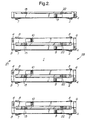
- Figure 2 shows a plan view of one example of apparatus according to the invention.
- the apparatus for controlling access comprises a passage (1) having a barrier (2, 3) controllable into an open condition and a closed condition, and means (4) for reading fare or toll data.
- the passage is formed between two side assemblies (5, 6).
- Each side assembly includes sensing means (11 - 26) for sensing the position of a plurality of subjects in the passage and providing corresponding signals.
- the sensing means comprises twenty sensor pairs, each pair comprising a transmitter (for example a light source) on one side of the passage and a receiver (for example a photoelectric cell detector for detecting light emitted by the light source) on the other side of the passage. Only one member of each pair is shown in Figure 1.
- the sensing means operates by sensing a break in a beam of energy travelling between the transmitter and the receiver caused by a subject in the passage.
- the beam of energy is a beam of light, however other beams such as infra-red beams or ultrasonic beams may be used as an alternative.
- the apparatus further comprises means (in the present example a microcomputer system having a memory) for associating given data with a signal corresponding to a given subject, and means for controlling the barrier (in the present example an electric motor and electromagnet together with a micro-controller), such that in operation when the given data associated with the signal corresponding to the given subject is invalid or absent, the barrier is controlled to be in the closed condition when the given subject approaches the barrier, thereby denying access to the given subject whilst allowing access to any other subject having a signal associated with valid data being in the passage between the given passenger and the barrier.
- means in the present example a microcomputer system having a memory
- the barrier in the present example an electric motor and electromagnet together with a micro-controller
- Each sensor pair is positioned such that the beam of energy travels directly across the passage (in a direction approximately perpendicular to the direction of motion of the subjects) from the transmitter to the corresponding receiver.
- the software operating the apparatus is arranged such that a new subject is only recognized at the entrance to the passage.
- Sensors pairs 11 and 13 (called the detection group) must both show an interrupted beam to denote a tall human subject. Signals from this sensor pair are immediately attributed to a new subject, and the information is stored in a memory location specific to the new subject. Signals arising from sensors not at the entrance to the passage do not result in a new subject being recognized.
- Short human subjects are sensed in the same way as described above for tall subjects, but in this case the relevant sensor pairs in the detection group are 11, 12 and (not) 14. Note that if a short subject jumps over sensor pair 12, it is likely that sensor pair 13 will be interrupted instead so that the short subject will be recognized as a tall subject. If a short subject is recognized, then sensor pair 13 will be ignored and sensor pairs 11 and 14 will be deemed to be adjacent pairs.
- the sensor pairs need not necessarily comprise a transmitter on one side and a receiver on the other side of the passage.
- the transmitter and receiver may be located next to one another on the same side of the passage together with a surface which reflects the radiation beam on the other side of the passage so that the beam is transmitted from the transmitter across the passage, then reflected from the reflective surface back across the passage to be received by the receiver.
- the system usually operates in what is known as a "normally open” mode in which the barrier is in its open condition unless a subject associated with absent or invalid data approaches the barrier.
- the apparatus may also be used in a "normally closed” mode in which the barrier remains in its closed condition unless a subject associated with valid data approaches the barrier.
- the access system can be set to either allow subjects from only one direction to obtain access or to allow access to subjects from either direction depending upon which subject is sensed by the system first.
- the former mode of operation is sometimes called the "unidirectional" mode whilst the latter mode of operation is sometimes known as the "bi-directional" mode.
- a turnstile or other barrier which always obstructs the passage to some extent may be used as an alternative (although in this case the advantage of greater throughput will not be so apparent).
- the barrier shown in Figure 3 is particularly advantageous for use in the above apparatus.
- the barrier comprises a first member (31) and a second member (32), the members being coupled to one another on opposite sides of a pivot (33), the first member (31) is constructed and arranged to inhibit access to a passage, the second member (32) having a surface (34) comprising a ferromagnetic material for cooperating with control means including an electromagnet (not shown) to hold the barrier in an open or closed condition.
- the members are both coupled to a pivotable shaft (33) which rotates about an axis of rotation (35).
- the axis of rotation is coaxial with the shaft, but other axes of rotation may be used as an alternative.
- the shaft may be pivotable in the plane of the axis of the shaft with an axis of rotation normal to the axis of the shaft and the two members being coupled to either end of the shaft.
- the first member (31) is padded so that if a passenger runs into the barrier when it is in a closed condition the passenger is not badly injured.
- the size of the ferromagnetic surface and the strength of the electromagnet is arranged such that a force of approximately 1100 Newton must be used to open the barrier when it is in its closed condition.
- the choice of this "release" force depends upon a number of factors. Firstly, if there is an emergency and a crowd of people are pushed against the barrier the release force must be set sufficiently low to prevent injury to passengers by crushing. However, the release force must not be too low or a strong passenger wanting to avoid paying a fare or toll could just push their way through the barrier.
- the present barrier it is easy to set and change this force simply by changing the electric current flowing to the electromagnet. Release forces in the range 700 - 2000 Newton may typically be employed.
- the force may be partly mechanical in addition to electromagnetic, for example by employing rolling element bearings which have to be forced out of locating cups into which they are biased (by for example a strong spring), or other mechanical systems commonly used in such barrier systems.
- the barrier of the present invention includes a magnetic latch.
- the barrier moves towards the subject when it closes, although other directions of movement may be employed if desired.
- it is advisable to have a mechanical break set at a similar force as that of the electromagnetic break so that if there is a crush of people wanting to enter the passage in the opposite way to that for which it is set up the barrier will move before injury occurs.
- It is also wise to have a battery backup for such systems so that the barrier may be controlled to be in an open condition if there is a power failure in addition to an emergency.
- Figure 4 shows a flow diagram of a method of controlling access by a subject from a first region to a second region via a passage having a barrier.
- the numbered blocks correspond to steps in the method.
- the blocks have the following significances.
- Block 40 denotes reading fare or toll data from a given subject.
- Block 41 denotes deciding if the data is valid or invalid.
- the next block (42) denotes storing a credit in a memory if the data is valid.
- Block 43 denotes sensing the presence and position of the given subject and providing at least one sensing signal as the given subject moves through the passage, thereby providing information on the position of the given subject in the passage with time.
- Block 44 denotes associating the credit or lack of a credit with the position of the given subject in the passage.
- Block 45 denotes controlling the barrier to substantially prevent access through the passage by the given subject when a lack of a credit is in association with the position of the given subject whilst allowing access by any other subject being in association with valid data and being in the passage between the given subject and the barrier.
Landscapes
- Physics & Mathematics (AREA)
- General Physics & Mathematics (AREA)
- Devices For Checking Fares Or Tickets At Control Points (AREA)
- Vehicle Body Suspensions (AREA)
- Selective Calling Equipment (AREA)
- Electrical Discharge Machining, Electrochemical Machining, And Combined Machining (AREA)
- Seal Device For Vehicle (AREA)
- Communication Control (AREA)
Claims (10)
- Barrière destinée à être utilisée dans un appareil de contrôle d'accès, la barrière comprenant un premier élément (31) et un second élément (32), les éléments étant couplés l'un à l'autre, le premier élément étant adapté pour interdire l'accès à un passage, le second élément ayant une surface (34) comprenant un matériau ferromagnétique pour coopérer avec des moyens de commande comprenant un électro-aimant pour maintenir la barrière dans un état ouvert ou fermé.
- Barrière selon la revendication 1, dans laquelle les éléments sont tous deux couplés à un arbre pivotant (33).
- Barrière selon la revendication 2, dans laquelle l'arbre peut tourner de manière axiale.
- Appareil de contrôle d'accès comprenant a) un passage ayant une barrière (2, 7) selon l'une quelconque des revendications précédentes pouvant être commandée pour se placer dans un état ouvert et dans un état fermé, b) des moyens (4) pour lire les données de tarif ou de droit de passage, c) des moyens de détection (11 à 26) pour détecter la position d'une pluralité de sujets se trouvant dans le passage et délivrant des signaux correspondants, d) des moyens pour associer les données de tarif ou de droit de passage fournies à un ou plusieurs signaux correspondant à un sujet donné, et e) des moyens pour commander la barrière, de telle sorte qu'en service, lorsque les données de tarif ou de droit de passage fournies correspondant au sujet donné ne sont pas valides ou sont absentes, la barrière est commandée pour être dans l'état fermé lorsque le sujet donné s'approche de la barrière, refusant l'accès au sujet donné tout en permettant l'accès à tout autre sujet se trouvant dans le passage entre le passager donné et la barrière.
- Appareil selon la revendication 4, dans lequel les moyens pour lire les données de tarif ou de droit de passage se composent d'un système de collecte d'argent, et les données comprennent au moins un élément du groupe se composant d'une carte de crédit, d'une carte à puce ou d'une ou plusieurs pièces de monnaie et/ou d'un ou de plusieurs billets de banque.
- Appareil selon la revendication 4, dans lequel les moyens pour lire les données de tarif ou de droit de passage se composent d'un système de lecture de ticket, et les données comprennent un ticket ou une carte codé(e).
- Appareil selon la revendication 4, construit et agencé de telle sorte que le sujet reste en possession du ticket ou de la carte en même temps qu'il/elle est lu(e) ou qu'il/elle est écrit(e).
- Appareil selon la revendication 4, dans lequel la barrière comprend un ou plusieurs éléments qui s'étendent dans le passage davantage quand la barrière se trouve dans l'état fermé que lorsque la barrière se trouve dans l'état ouvert.
- Appareil selon la revendication 8, dans lequel un ou plusieurs éléments peuvent pivoter autour d'un axe dans un plan sensiblement parallèle à la direction d'accès.
- Appareil selon les revendications 4 à 9, dans lequel l'appareil comprend une batterie pour fournir de l'énergie électrique en cas d'urgence.
Applications Claiming Priority (3)
| Application Number | Priority Date | Filing Date | Title |
|---|---|---|---|
| GB9508512 | 1995-04-26 | ||
| GBGB9508512.2A GB9508512D0 (en) | 1995-04-26 | 1995-04-26 | "Apparatus and method for controlling access" |
| PCT/GB1996/000963 WO1996034367A1 (fr) | 1995-04-26 | 1996-04-23 | Appareil de controle d'acces |
Publications (2)
| Publication Number | Publication Date |
|---|---|
| EP0823103A1 EP0823103A1 (fr) | 1998-02-11 |
| EP0823103B1 true EP0823103B1 (fr) | 1998-09-30 |
Family
ID=10773576
Family Applications (1)
| Application Number | Title | Priority Date | Filing Date |
|---|---|---|---|
| EP96910136A Expired - Lifetime EP0823103B1 (fr) | 1995-04-26 | 1996-04-23 | Appareil de controle d'acces |
Country Status (8)
| Country | Link |
|---|---|
| EP (1) | EP0823103B1 (fr) |
| KR (1) | KR19990008165A (fr) |
| CN (1) | CN1182493A (fr) |
| AT (1) | ATE171802T1 (fr) |
| CA (1) | CA2219803A1 (fr) |
| DE (1) | DE69600732T2 (fr) |
| GB (1) | GB9508512D0 (fr) |
| WO (1) | WO1996034367A1 (fr) |
Cited By (1)
| Publication number | Priority date | Publication date | Assignee | Title |
|---|---|---|---|---|
| DE102012001084A1 (de) * | 2012-01-20 | 2013-07-25 | Bundesrepublik Deutschland, vertreten durch das Bundesministerium der Verteidigung, dieses vertreten durch das Bundesamt für Ausrüstung, Informationstechnik und Nutzung der Bundeswehr | Elektronische Schleuse |
Families Citing this family (5)
| Publication number | Priority date | Publication date | Assignee | Title |
|---|---|---|---|---|
| FR2849519B1 (fr) * | 2002-12-31 | 2005-03-11 | Automatic Systems | Porte automatisee pour permettre ou interdire l'acces a un espace ou un vehicule de transport, en particulier a une salle d'embarquement ou a un avion |
| DE102004013965B3 (de) * | 2004-03-19 | 2005-12-01 | Skidata Ag | Zutrittskontrollvorrichtung |
| CN100559402C (zh) * | 2005-11-18 | 2009-11-11 | 南京熊猫机电仪技术有限公司 | 检票系统中的扇门控制用传感器的安装方法 |
| CN102393972B (zh) * | 2011-07-21 | 2014-04-23 | 深圳市爱森斯信息技术有限公司 | 闸机通道检测系统及其检测方法 |
| DE102020113114A1 (de) * | 2020-05-14 | 2021-11-18 | Kaba Gallenschütz GmbH | Passiererkennungssystem und Verfahren zur berührungslosen Überwachung |
Family Cites Families (6)
| Publication number | Priority date | Publication date | Assignee | Title |
|---|---|---|---|---|
| GB1263542A (en) * | 1968-06-14 | 1972-02-09 | Omron Tateisi Electronics Co | An automatic ticket gate |
| FR2029911A5 (fr) * | 1969-01-31 | 1970-10-23 | Compteurs Comp D | |
| US3791687A (en) * | 1972-06-19 | 1974-02-12 | H Schroeder | Pop up magnetic door stop and holder |
| EP0045197A1 (fr) * | 1980-07-28 | 1982-02-03 | Bsg (Security) Limited | Serrure électromagnétique |
| ZA937447B (en) * | 1992-10-07 | 1994-03-25 | Pieter Johannes Eras Vermeulen | Apparatus and a method for classifying of objects along a passage |
| DE9314530U1 (de) * | 1993-09-25 | 1993-11-04 | Wanzl Gmbh & Co. Entwicklungs-Kg, 89340 Leipheim | Schwenktüre für einen Personendurchgang |
-
1995
- 1995-04-26 GB GBGB9508512.2A patent/GB9508512D0/en active Pending
-
1996
- 1996-04-23 KR KR1019970707690A patent/KR19990008165A/ko not_active Abandoned
- 1996-04-23 EP EP96910136A patent/EP0823103B1/fr not_active Expired - Lifetime
- 1996-04-23 CA CA002219803A patent/CA2219803A1/fr not_active Abandoned
- 1996-04-23 AT AT96910136T patent/ATE171802T1/de not_active IP Right Cessation
- 1996-04-23 WO PCT/GB1996/000963 patent/WO1996034367A1/fr not_active Ceased
- 1996-04-23 CN CN96193514A patent/CN1182493A/zh active Pending
- 1996-04-23 DE DE69600732T patent/DE69600732T2/de not_active Expired - Fee Related
Cited By (1)
| Publication number | Priority date | Publication date | Assignee | Title |
|---|---|---|---|---|
| DE102012001084A1 (de) * | 2012-01-20 | 2013-07-25 | Bundesrepublik Deutschland, vertreten durch das Bundesministerium der Verteidigung, dieses vertreten durch das Bundesamt für Ausrüstung, Informationstechnik und Nutzung der Bundeswehr | Elektronische Schleuse |
Also Published As
| Publication number | Publication date |
|---|---|
| DE69600732T2 (de) | 1999-05-12 |
| GB9508512D0 (en) | 1995-06-14 |
| ATE171802T1 (de) | 1998-10-15 |
| KR19990008165A (ko) | 1999-01-25 |
| EP0823103A1 (fr) | 1998-02-11 |
| DE69600732D1 (de) | 1998-11-05 |
| CN1182493A (zh) | 1998-05-20 |
| CA2219803A1 (fr) | 1996-10-31 |
| WO1996034367A1 (fr) | 1996-10-31 |
Similar Documents
| Publication | Publication Date | Title |
|---|---|---|
| US5845692A (en) | Rapid access portal | |
| US3386202A (en) | Automatic passageway | |
| US5333410A (en) | Controllable barrier system for preventing unpaid admission to a fee-paid area | |
| US8827155B2 (en) | Access control gate | |
| US20060101716A1 (en) | Automatic gate and associated method for permitting or preventing access | |
| US6980920B2 (en) | Embedded sensor system for tracking moving objects | |
| JPH09147192A (ja) | 現金自動取引装置及びその防犯システム | |
| US6170194B1 (en) | Turning blocking device | |
| EP0823103A1 (fr) | Appareil de controle d'acces | |
| CN114076989A (zh) | 一种人员通道装置和控制方法 | |
| GB1245189A (en) | Improvements in gates | |
| CN212623139U (zh) | 一种人员通道装置 | |
| JP2004227294A (ja) | 自動改札機 | |
| KR20100082580A (ko) | 지문 인식형 보안 출입 게이트 및 이를 이용한 출입 통제 시스템 | |
| CN119863858B (zh) | 一种基于多传感器的门禁装置 | |
| JP2000099776A (ja) | 自動改札装置 | |
| JP2019095929A (ja) | 入退出管理装置 | |
| JP3637093B2 (ja) | 自動改札装置 | |
| JPH0565783A (ja) | 部内への立入を管理する回転ドア | |
| JP3900649B2 (ja) | 駐輪場ゲートの不正連続通過防止システム | |
| EP4418223A1 (fr) | Dispositif de contrôle d'accès pour une personne et/ou un objet mobile et procédé de contrôle de l'ouverture et/ou de la fermeture d'un dispositif de blocage | |
| JP3728863B2 (ja) | 自動改札機 | |
| EP0504953B1 (fr) | Tourniquet, en particulier pour protéger l'accès à une chambre | |
| KR19980028176U (ko) | 양방향 개찰기 자동전환장치 | |
| JP2695706B2 (ja) | 両方向型自動改札機 |
Legal Events
| Date | Code | Title | Description |
|---|---|---|---|
| PUAI | Public reference made under article 153(3) epc to a published international application that has entered the european phase |
Free format text: ORIGINAL CODE: 0009012 |
|
| 17P | Request for examination filed |
Effective date: 19971110 |
|
| AK | Designated contracting states |
Kind code of ref document: A1 Designated state(s): AT BE CH DE DK ES FR GB GR IE IT LI LU MC NL PT SE |
|
| GRAG | Despatch of communication of intention to grant |
Free format text: ORIGINAL CODE: EPIDOS AGRA |
|
| GRAG | Despatch of communication of intention to grant |
Free format text: ORIGINAL CODE: EPIDOS AGRA |
|
| GRAH | Despatch of communication of intention to grant a patent |
Free format text: ORIGINAL CODE: EPIDOS IGRA |
|
| 17Q | First examination report despatched |
Effective date: 19980217 |
|
| GRAH | Despatch of communication of intention to grant a patent |
Free format text: ORIGINAL CODE: EPIDOS IGRA |
|
| GRAA | (expected) grant |
Free format text: ORIGINAL CODE: 0009210 |
|
| AK | Designated contracting states |
Kind code of ref document: B1 Designated state(s): AT BE CH DE DK ES FR GB GR IE IT LI LU MC NL PT SE |
|
| PG25 | Lapsed in a contracting state [announced via postgrant information from national office to epo] |
Ref country code: NL Free format text: LAPSE BECAUSE OF FAILURE TO SUBMIT A TRANSLATION OF THE DESCRIPTION OR TO PAY THE FEE WITHIN THE PRESCRIBED TIME-LIMIT Effective date: 19980930 Ref country code: LI Free format text: LAPSE BECAUSE OF FAILURE TO SUBMIT A TRANSLATION OF THE DESCRIPTION OR TO PAY THE FEE WITHIN THE PRESCRIBED TIME-LIMIT Effective date: 19980930 Ref country code: IT Free format text: LAPSE BECAUSE OF FAILURE TO SUBMIT A TRANSLATION OF THE DESCRIPTION OR TO PAY THE FEE WITHIN THE PRE;WARNING: LAPSES OF ITALIAN PATENTS WITH EFFECTIVE DATE BEFORE 2007 MAY HAVE OCCURRED AT ANY TIME BEFORE 2007. THE CORRECT EFFECTIVE DATE MAY BE DIFFERENT FROM THE ONE RECORDED.SCRIBED TIME-LIMIT Effective date: 19980930 Ref country code: GR Free format text: LAPSE BECAUSE OF NON-PAYMENT OF DUE FEES Effective date: 19980930 Ref country code: ES Free format text: THE PATENT HAS BEEN ANNULLED BY A DECISION OF A NATIONAL AUTHORITY Effective date: 19980930 Ref country code: CH Free format text: LAPSE BECAUSE OF FAILURE TO SUBMIT A TRANSLATION OF THE DESCRIPTION OR TO PAY THE FEE WITHIN THE PRESCRIBED TIME-LIMIT Effective date: 19980930 Ref country code: AT Free format text: LAPSE BECAUSE OF FAILURE TO SUBMIT A TRANSLATION OF THE DESCRIPTION OR TO PAY THE FEE WITHIN THE PRESCRIBED TIME-LIMIT Effective date: 19980930 |
|
| REF | Corresponds to: |
Ref document number: 171802 Country of ref document: AT Date of ref document: 19981015 Kind code of ref document: T |
|
| REG | Reference to a national code |
Ref country code: CH Ref legal event code: EP |
|
| REF | Corresponds to: |
Ref document number: 69600732 Country of ref document: DE Date of ref document: 19981105 |
|
| REG | Reference to a national code |
Ref country code: IE Ref legal event code: FG4D |
|
| ET | Fr: translation filed | ||
| PG25 | Lapsed in a contracting state [announced via postgrant information from national office to epo] |
Ref country code: PT Free format text: LAPSE BECAUSE OF FAILURE TO SUBMIT A TRANSLATION OF THE DESCRIPTION OR TO PAY THE FEE WITHIN THE PRESCRIBED TIME-LIMIT Effective date: 19981230 |
|
| PG25 | Lapsed in a contracting state [announced via postgrant information from national office to epo] |
Ref country code: SE Free format text: LAPSE BECAUSE OF FAILURE TO SUBMIT A TRANSLATION OF THE DESCRIPTION OR TO PAY THE FEE WITHIN THE PRESCRIBED TIME-LIMIT Effective date: 19981231 Ref country code: DK Free format text: LAPSE BECAUSE OF FAILURE TO SUBMIT A TRANSLATION OF THE DESCRIPTION OR TO PAY THE FEE WITHIN THE PRESCRIBED TIME-LIMIT Effective date: 19981231 |
|
| NLV1 | Nl: lapsed or annulled due to failure to fulfill the requirements of art. 29p and 29m of the patents act | ||
| REG | Reference to a national code |
Ref country code: CH Ref legal event code: PL |
|
| PG25 | Lapsed in a contracting state [announced via postgrant information from national office to epo] |
Ref country code: LU Free format text: LAPSE BECAUSE OF NON-PAYMENT OF DUE FEES Effective date: 19990423 Ref country code: IE Free format text: LAPSE BECAUSE OF NON-PAYMENT OF DUE FEES Effective date: 19990423 |
|
| PG25 | Lapsed in a contracting state [announced via postgrant information from national office to epo] |
Ref country code: BE Free format text: LAPSE BECAUSE OF NON-PAYMENT OF DUE FEES Effective date: 19990430 |
|
| PLBE | No opposition filed within time limit |
Free format text: ORIGINAL CODE: 0009261 |
|
| STAA | Information on the status of an ep patent application or granted ep patent |
Free format text: STATUS: NO OPPOSITION FILED WITHIN TIME LIMIT |
|
| 26N | No opposition filed | ||
| BERE | Be: lapsed |
Owner name: THORN TRANSIT SYSTEMS INTERNATIONAL LTD Effective date: 19990430 |
|
| PG25 | Lapsed in a contracting state [announced via postgrant information from national office to epo] |
Ref country code: MC Free format text: LAPSE BECAUSE OF NON-PAYMENT OF DUE FEES Effective date: 19991031 |
|
| PG25 | Lapsed in a contracting state [announced via postgrant information from national office to epo] |
Ref country code: FR Free format text: LAPSE BECAUSE OF NON-PAYMENT OF DUE FEES Effective date: 19991231 |
|
| REG | Reference to a national code |
Ref country code: FR Ref legal event code: ST |
|
| PG25 | Lapsed in a contracting state [announced via postgrant information from national office to epo] |
Ref country code: DE Free format text: LAPSE BECAUSE OF NON-PAYMENT OF DUE FEES Effective date: 20000201 |
|
| REG | Reference to a national code |
Ref country code: IE Ref legal event code: MM4A |
|
| PG25 | Lapsed in a contracting state [announced via postgrant information from national office to epo] |
Ref country code: GB Free format text: LAPSE BECAUSE OF NON-PAYMENT OF DUE FEES Effective date: 20000423 |
|
| GBPC | Gb: european patent ceased through non-payment of renewal fee |
Effective date: 20000423 |