EP0823585A2 - Versorgungsanlage, insbesondere für toxische und brennbare Gase - Google Patents
Versorgungsanlage, insbesondere für toxische und brennbare Gase Download PDFInfo
- Publication number
- EP0823585A2 EP0823585A2 EP97112685A EP97112685A EP0823585A2 EP 0823585 A2 EP0823585 A2 EP 0823585A2 EP 97112685 A EP97112685 A EP 97112685A EP 97112685 A EP97112685 A EP 97112685A EP 0823585 A2 EP0823585 A2 EP 0823585A2
- Authority
- EP
- European Patent Office
- Prior art keywords
- absorber
- pressure
- line
- gas
- toxic
- Prior art date
- Legal status (The legal status is an assumption and is not a legal conclusion. Google has not performed a legal analysis and makes no representation as to the accuracy of the status listed.)
- Withdrawn
Links
Images
Classifications
-
- F—MECHANICAL ENGINEERING; LIGHTING; HEATING; WEAPONS; BLASTING
- F17—STORING OR DISTRIBUTING GASES OR LIQUIDS
- F17C—VESSELS FOR CONTAINING OR STORING COMPRESSED, LIQUEFIED OR SOLIDIFIED GASES; FIXED-CAPACITY GAS-HOLDERS; FILLING VESSELS WITH, OR DISCHARGING FROM VESSELS, COMPRESSED, LIQUEFIED, OR SOLIDIFIED GASES
- F17C7/00—Methods or apparatus for discharging liquefied, solidified, or compressed gases from pressure vessels, not covered by another subclass
-
- F—MECHANICAL ENGINEERING; LIGHTING; HEATING; WEAPONS; BLASTING
- F17—STORING OR DISTRIBUTING GASES OR LIQUIDS
- F17C—VESSELS FOR CONTAINING OR STORING COMPRESSED, LIQUEFIED OR SOLIDIFIED GASES; FIXED-CAPACITY GAS-HOLDERS; FILLING VESSELS WITH, OR DISCHARGING FROM VESSELS, COMPRESSED, LIQUEFIED, OR SOLIDIFIED GASES
- F17C13/00—Details of vessels or of the filling or discharging of vessels
- F17C13/04—Arrangement or mounting of valves
-
- F—MECHANICAL ENGINEERING; LIGHTING; HEATING; WEAPONS; BLASTING
- F17—STORING OR DISTRIBUTING GASES OR LIQUIDS
- F17C—VESSELS FOR CONTAINING OR STORING COMPRESSED, LIQUEFIED OR SOLIDIFIED GASES; FIXED-CAPACITY GAS-HOLDERS; FILLING VESSELS WITH, OR DISCHARGING FROM VESSELS, COMPRESSED, LIQUEFIED, OR SOLIDIFIED GASES
- F17C2205/00—Vessel construction, in particular mounting arrangements, attachments or identifications means
- F17C2205/01—Mounting arrangements
- F17C2205/0103—Exterior arrangements
- F17C2205/0111—Boxes
-
- F—MECHANICAL ENGINEERING; LIGHTING; HEATING; WEAPONS; BLASTING
- F17—STORING OR DISTRIBUTING GASES OR LIQUIDS
- F17C—VESSELS FOR CONTAINING OR STORING COMPRESSED, LIQUEFIED OR SOLIDIFIED GASES; FIXED-CAPACITY GAS-HOLDERS; FILLING VESSELS WITH, OR DISCHARGING FROM VESSELS, COMPRESSED, LIQUEFIED, OR SOLIDIFIED GASES
- F17C2205/00—Vessel construction, in particular mounting arrangements, attachments or identifications means
- F17C2205/01—Mounting arrangements
- F17C2205/0123—Mounting arrangements characterised by number of vessels
- F17C2205/013—Two or more vessels
- F17C2205/0134—Two or more vessels characterised by the presence of fluid connection between vessels
- F17C2205/0142—Two or more vessels characterised by the presence of fluid connection between vessels bundled in parallel
-
- F—MECHANICAL ENGINEERING; LIGHTING; HEATING; WEAPONS; BLASTING
- F17—STORING OR DISTRIBUTING GASES OR LIQUIDS
- F17C—VESSELS FOR CONTAINING OR STORING COMPRESSED, LIQUEFIED OR SOLIDIFIED GASES; FIXED-CAPACITY GAS-HOLDERS; FILLING VESSELS WITH, OR DISCHARGING FROM VESSELS, COMPRESSED, LIQUEFIED, OR SOLIDIFIED GASES
- F17C2205/00—Vessel construction, in particular mounting arrangements, attachments or identifications means
- F17C2205/03—Fluid connections, filters, valves, closure means or other attachments
- F17C2205/0302—Fittings, valves, filters, or components in connection with the gas storage device
- F17C2205/0323—Valves
Definitions
- the invention relates to a supply system, in particular for toxic and combustible Gases, with at least one storage container which contains the gas and with a sampling line and an absorber is connected.
- Bottle bundles which consist of individual by means of a brazed, high pressure tested Bottles connected to the collecting line are made with an extraction line connected, which directs the fluorine to the places where it is needed.
- extraction line connected to the places where it is needed.
- Several bundles of bottles are regularly used to ensure gas supply connected to the sampling line via a switchover device. When the gas pressure of a bottle bundle comes to an end, the bottle bundle becomes switched off from the sampling line via the switchover device and a full one Bottle bundle switched on to the sampling line.
- a Absorber provided, which is connected to the connecting lines of the bottle bundle is and thus that in the connecting lines or the bottle bundle residual gas can take up.
- the absorber can only neutralize a certain amount of gas per unit of time, may the pressure of the in the connecting lines or if necessary residual gas in the bottle bundle when the absorber is switched on the connecting lines must not be too large, otherwise the ones supplied to the absorber The amount of gas would be too large, with the result that part of the gas would not would be neutralized and enter the environment as a toxic or flammable substance would.
- a pressure reducer is arranged between the storage containers and the absorber.
- the pressure reducer advantageously ensures that only a certain amount of gas is passed to the absorber.
- the amount of gas can be determined by setting the back pressure, i.e. the pressure on the side of the absorber. With a larger line leading to the absorber, a lower back pressure must be set than with smaller connecting lines. For example, if the line diameter of the pipeline leading to the absorber is 12 mm with a wall thickness of 1 mm, the back pressure for an absorber with an F 2 absorption capacity of 3 g F 2 / sec. Air should be set to 3 bar, because then only 2.5 g F 2 / sec.
- the gas pressure reducer is set to a back pressure of less than 3 bar in a supply system according to the invention, the F 2 absorber can absorb any residual gas amount from each bundle if the bundle valve is leaking.
- the pressure reducer is therefore advantageously designed for a pre-pressure of 200 bar and an adjustable back pressure of 0 to 10 bar.
- a vacuum pump is provided, which is located in the absorber line and the connecting lines Gas sucks through the absorber. It is particularly advantageous if the Pressure reducer can be sucked through from the vacuum side. This can ensure be that after the bundle changeover the residual gas from the line between the absorber and the switching station and between the storage container and the switching station or from the reservoir itself is sucked. This means that after loosening the reservoir from the Connection lines no residual gas flows out of the line. This is particularly so In the case of supply systems for fluorine, this is a great advantage, since fluorine no longer comes from the Lines escapes and poisoned people through the formation of hydrogen fluoride or Bottle bundles corrode from the inside due to leaky bottle valves be destroyed.
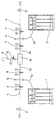
- FIG. A supply system according to the invention It shows the only FIG. A supply system according to the invention.
- a supply system there are two bundles of bottles 1 and 2 connected to a removal line 3 via a switching device 10.
- the bundles of bottles 1, 2 are each via a flexible line 1a, 2a with permanently installed Connection lines 1b, 2b connected.
- connection lines 1b, 2b are to the extraction line 3 towards the first pressure reducer 8, 9.
- the pressure reducer 8, 9 the gas pressure prevailing in the cylinder bundles 1, 2 is reduced to the operating pressure.
- the connecting lines 1b, 2b there are between bottle bundles 1, 2 and pressure reducer 8, 9 pressure switch 13, 14, which in the connecting lines 1b, 2b monitor the prevailing gas pressure.
- the connecting lines 1b, 2b are further connected to absorber lines 4, 5, which each have an absorber, not shown, with the connecting lines 1b, 2b and thus connect to the bundles of bottles 1, 2 via the first lines 1a, 2a.
- Second pressure reducers 6, 7 are connected in the absorber lines 4, 5.
- the second pressure reducers 6, 7 are for a pre-pressure of 200 bar and an adjustable Back pressure designed from 0 to 10 bar.
- solenoid valves 11, 12, which close normally before the absorber, are switched, which the absorbers from the absorber lines 4, 5 and thus from the Can cut lines 1a, 2a, 1b, 2b.
- the pressure switch 13 shown on the left reports that the Pressure of the bottle bundle is 5 bar, it sends a signal to the switching station 10, which then separates the supply line 1b from the extraction line 3 and the supply line 2b connects to the extraction line 3.
- the supply line 1b is closed in a pressure-tight manner after the changeover in the changeover station 10.
- the state is shown in which the right bottle bundle 2 with the extraction line 3 connected and the supply line 1b in the switching station 10 is closed pressure-tight.
- the pressure in the supply line is 1b in the selected one Example 5 bar.
- the solenoid valve 11 is opened. That is in the connecting line 1b and the supply line 1a residual gas is via the absorber line 4th fed to the absorber.
- the second pressure reducer 6 the pressure at one Line diameter of the absorber line 4 of 12 mm with a wall thickness reduced from 1 mm to, for example, 3 bar in the absorber line 4. It is therefore ensures that only as much residual gas is supplied to the absorber per unit of time, how he can neutralize.
- a vacuum pump not shown, which is located in the pipe network residual gas sucks through the absorber.
- the second pressure reducer is for this purpose 6, 7 designed so that they can be sucked through from the back pressure side. That means, that even if there is no more pressure on the pre-pressure side, gas can flow through the pressure reducer if the pressure on the back pressure side is less than on the pre-printed page.
Landscapes
- Engineering & Computer Science (AREA)
- Mechanical Engineering (AREA)
- General Engineering & Computer Science (AREA)
- Filling Or Discharging Of Gas Storage Vessels (AREA)
Abstract
Description
Claims (4)
- Versorgungsanlage, insbesondere für toxische und brennbare Gase, mit wenigstens einem Vorratsbehälter (1, 2), welcher das Gas enthält und mit einer Entnahmeleitung (3) sowie einem Absorber verbunden ist,
dadurch gekennzeichnet,
daß zwischen dem Vorratsbehälter (1, 2) und dem Absorber ein Druckminderer (6, 7) angeordnet ist. - Versorgungsanlage nach Anspruch 1,
dadurch gekennzeichnet,
daß der Druckminderer (6, 7) für einen Vordruck von 200 bar und einen einstellbaren Hinterdruck von 0 bis 10 bar ausgelegt ist. - Versorgungsanlage nach Anspruch 1 oder 2,
dadurch gekennzeichnet,
daß der Absorber über eine Absorberleitung (4, 5) mit dem Vorratsbehälter (1, 2) verbunden ist und eine Vakuumpumpe vorgesehen ist, welche das sich in der Absorberleitung befindliche Gas durch den Absorber saugt. - Versorgungsanlage nach einem der Ansprüche 1 bis 3,
dadurch gekennzeichnet,
daß der Druckminderer (6, 7) von der Hinterdruckseite her durchsaugbar ist.
Applications Claiming Priority (2)
| Application Number | Priority Date | Filing Date | Title |
|---|---|---|---|
| DE19632015A DE19632015C1 (de) | 1996-08-08 | 1996-08-08 | Versorgungsanlage, insbesondere für toxische und brennbare Gase |
| DE19632015 | 1996-08-08 |
Publications (2)
| Publication Number | Publication Date |
|---|---|
| EP0823585A2 true EP0823585A2 (de) | 1998-02-11 |
| EP0823585A3 EP0823585A3 (de) | 1998-12-09 |
Family
ID=7802125
Family Applications (1)
| Application Number | Title | Priority Date | Filing Date |
|---|---|---|---|
| EP97112685A Withdrawn EP0823585A3 (de) | 1996-08-08 | 1997-07-24 | Versorgungsanlage, insbesondere für toxische und brennbare Gase |
Country Status (3)
| Country | Link |
|---|---|
| EP (1) | EP0823585A3 (de) |
| DE (1) | DE19632015C1 (de) |
| ZA (1) | ZA971454B (de) |
Families Citing this family (3)
| Publication number | Priority date | Publication date | Assignee | Title |
|---|---|---|---|---|
| RU2242668C1 (ru) * | 2003-03-03 | 2004-12-20 | Мокеев Юрий Алексеевич | Аккумулятор газа |
| RU2300695C9 (ru) * | 2005-03-18 | 2008-06-20 | Юрий Алексеевич Мокеев | Способ наполнения газом сосуда при вводе его в эксплуатацию |
| RU2317478C9 (ru) * | 2005-03-18 | 2008-06-10 | Юрий Алексеевич Мокеев | Способ удаления газа из сосуда при выводе его из эксплуатации |
Family Cites Families (5)
| Publication number | Priority date | Publication date | Assignee | Title |
|---|---|---|---|---|
| JPS6326500A (ja) * | 1986-07-18 | 1988-02-04 | Fujitsu Ltd | 圧縮ガス容器系統自動切換装置 |
| US5151395A (en) * | 1987-03-24 | 1992-09-29 | Novapure Corporation | Bulk gas sorption and apparatus, gas containment/treatment system comprising same, and sorbent composition therefor |
| US5250323A (en) * | 1989-10-30 | 1993-10-05 | Kabushiki Kaisha Toshiba | Chemical vapor growth apparatus having an exhaust device including trap |
| US5137047A (en) * | 1990-08-24 | 1992-08-11 | Mark George | Delivery of reactive gas from gas pad to process tool |
| DE9217477U1 (de) * | 1992-12-15 | 1993-04-15 | Pneumatik Berlin Gmbh, 13088 Berlin | Druckluftspeicher mit automatisch arbeitendem Armaturenblock für Energieschaltanlagen |
-
1996
- 1996-08-08 DE DE19632015A patent/DE19632015C1/de not_active Expired - Fee Related
-
1997
- 1997-02-20 ZA ZA9701454A patent/ZA971454B/xx unknown
- 1997-07-24 EP EP97112685A patent/EP0823585A3/de not_active Withdrawn
Also Published As
| Publication number | Publication date |
|---|---|
| EP0823585A3 (de) | 1998-12-09 |
| DE19632015C1 (de) | 1998-01-15 |
| ZA971454B (en) | 1997-08-27 |
Similar Documents
| Publication | Publication Date | Title |
|---|---|---|
| DE3806998C2 (de) | Steuereinheit für unter Druck stehende Gase | |
| DE102020108176A1 (de) | Brennstoffversorgungssystem und Kraftfahrzeug | |
| DE3004594C2 (de) | Warnsignalvorrichtung für Atemschutzgeräte | |
| DE69400792T2 (de) | Vorrichtung zur erzeugung einer inerten atmosphäre innerhalb eines lagertanks | |
| EP0823585A2 (de) | Versorgungsanlage, insbesondere für toxische und brennbare Gase | |
| EP0431335B1 (de) | Vorrichtung zum Entsorgen des Kältemittels von Absorptions-Kältesystemen | |
| DE4222864C2 (de) | Sicherheitseinrichtung für Anschlüsse und/oder Ventile | |
| DE3128382A1 (de) | Hydraulische schaltvorrichtung fuer pumpen variabler verdraengung | |
| EP1073531B1 (de) | Vorrichtung und verfahren zur druckwechselspülung | |
| DE69412859T2 (de) | Hochdruckventil | |
| EP1079292B1 (de) | Gasdruckregelanlage | |
| EP0569020B1 (de) | Anlage zur sicheren Entsorgung eines Systems zum Transport von Gefahrgasen | |
| AT523896B1 (de) | Prüfstandsystem zum Prüfen von zumindest einer Brennstoffzelle | |
| DE2746382C2 (de) | ||
| DE19961080A1 (de) | Vorrichtung zur Entnahme eines Fluides aus einem Speicherbehälter | |
| DE4308801C2 (de) | Verfahren zur Entleerung von Acetylenflaschen oder Acetylenflaschenbündeln und Einrichtung zur Durchführung des Verfahrens | |
| DE10056602C1 (de) | Beschriftungsvorrichtung und Extrusionsanlage mit einer solchen Beschriftungsvorrichtung | |
| DE9203660U1 (de) | Reinigungsvorrichtung für ein Kraftstoffeinspritzsystem | |
| DE19615573A1 (de) | Sprühvorrichtung, insbesondere für einen Montageautomaten | |
| DE69916724T2 (de) | Vorrichtung und verfahren zum zuführen von arbeitsmittel an hermetische kreisläufe | |
| WO2017137388A1 (de) | Vorrichtung zur zentralen gasversorgung | |
| EP0475240B1 (de) | Druckluftanlage, insbesondere Teil einer Druckluftbremsanlage eines Fahrzeuges | |
| EP1369679A2 (de) | Verfahren und Vorrichtung zum Prüfen von Feuerwehrschläuchen | |
| DE19625117C1 (de) | Druckgasbehälter, insbesondere für toxische und brennbare Gase | |
| DE29619975U1 (de) | Sprühvorrichtung zum flächigen Auftragen von Flüssigkeiten |
Legal Events
| Date | Code | Title | Description |
|---|---|---|---|
| PUAI | Public reference made under article 153(3) epc to a published international application that has entered the european phase |
Free format text: ORIGINAL CODE: 0009012 |
|
| AK | Designated contracting states |
Kind code of ref document: A2 Designated state(s): AT BE CH ES FR GB IT LI NL |
|
| PUAL | Search report despatched |
Free format text: ORIGINAL CODE: 0009013 |
|
| AK | Designated contracting states |
Kind code of ref document: A3 Designated state(s): AT BE CH DE DK ES FI FR GB GR IE IT LI LU MC NL PT SE |
|
| 17P | Request for examination filed |
Effective date: 19981202 |
|
| AKX | Designation fees paid |
Free format text: AT BE CH ES FR GB IT LI NL |
|
| REG | Reference to a national code |
Ref country code: DE Ref legal event code: 8566 |
|
| STAA | Information on the status of an ep patent application or granted ep patent |
Free format text: STATUS: THE APPLICATION IS DEEMED TO BE WITHDRAWN |
|
| 18D | Application deemed to be withdrawn |
Effective date: 20020201 |