EP0823599A2 - Gasbeheizter Wassererhitzer - Google Patents
Gasbeheizter Wassererhitzer Download PDFInfo
- Publication number
- EP0823599A2 EP0823599A2 EP97109718A EP97109718A EP0823599A2 EP 0823599 A2 EP0823599 A2 EP 0823599A2 EP 97109718 A EP97109718 A EP 97109718A EP 97109718 A EP97109718 A EP 97109718A EP 0823599 A2 EP0823599 A2 EP 0823599A2
- Authority
- EP
- European Patent Office
- Prior art keywords
- wall
- water
- casting
- combustion chamber
- chambers
- Prior art date
- Legal status (The legal status is an assumption and is not a legal conclusion. Google has not performed a legal analysis and makes no representation as to the accuracy of the status listed.)
- Granted
Links
- XLYOFNOQVPJJNP-UHFFFAOYSA-N water Substances O XLYOFNOQVPJJNP-UHFFFAOYSA-N 0.000 title claims abstract description 31
- 238000005266 casting Methods 0.000 claims abstract description 15
- 238000002485 combustion reaction Methods 0.000 claims description 17
- 230000015572 biosynthetic process Effects 0.000 claims description 2
- 238000009795 derivation Methods 0.000 claims 1
- 238000007789 sealing Methods 0.000 abstract 1
- 238000004512 die casting Methods 0.000 description 4
- 238000010276 construction Methods 0.000 description 2
- 238000001816 cooling Methods 0.000 description 2
- 239000002184 metal Substances 0.000 description 2
- 239000008236 heating water Substances 0.000 description 1
- 238000004519 manufacturing process Methods 0.000 description 1
Images
Classifications
-
- F—MECHANICAL ENGINEERING; LIGHTING; HEATING; WEAPONS; BLASTING
- F24—HEATING; RANGES; VENTILATING
- F24H—FLUID HEATERS, e.g. WATER OR AIR HEATERS, HAVING HEAT-GENERATING MEANS, e.g. HEAT PUMPS, IN GENERAL
- F24H1/00—Water heaters, e.g. boilers, continuous-flow heaters or water-storage heaters
- F24H1/22—Water heaters other than continuous-flow or water-storage heaters, e.g. water heaters for central heating
- F24H1/40—Water heaters other than continuous-flow or water-storage heaters, e.g. water heaters for central heating with water tube or tubes
-
- F—MECHANICAL ENGINEERING; LIGHTING; HEATING; WEAPONS; BLASTING
- F24—HEATING; RANGES; VENTILATING
- F24H—FLUID HEATERS, e.g. WATER OR AIR HEATERS, HAVING HEAT-GENERATING MEANS, e.g. HEAT PUMPS, IN GENERAL
- F24H9/00—Details
- F24H9/14—Arrangements for connecting different sections, e.g. in water heaters
-
- F—MECHANICAL ENGINEERING; LIGHTING; HEATING; WEAPONS; BLASTING
- F24—HEATING; RANGES; VENTILATING
- F24H—FLUID HEATERS, e.g. WATER OR AIR HEATERS, HAVING HEAT-GENERATING MEANS, e.g. HEAT PUMPS, IN GENERAL
- F24H9/00—Details
- F24H9/14—Arrangements for connecting different sections, e.g. in water heaters
- F24H9/146—Connecting elements of a heat exchanger
Definitions
- the invention is based on a gas-fired water heater according to the genus of the main claim.
- a known Water heater of this type (EP A2 0 213 792) is the as Casting trained heat exchanger on the combustion chamber set up as an independent assembly in Sheet metal construction is executed.
- the arrangement according to the invention with the features of The main claim has the advantage that the casting of the Heat exchanger and the combustion chamber in one operation a die casting tool largely automated in short Cycle time can be manufactured. Connection operations of the heat exchanger with the combustion chamber are also eliminated may be necessary for a sheet metal construction Support elements are not needed because of the casting solution is self-supporting.
- a production-oriented execution results if that Casting of the heat exchanger at the inputs and outputs of the Water pipes each have a wall plate connecting the water pipes has to form water chambers with wall bridges and with means for fixing the water chambers tight final cover are provided.
- a combustion chamber cooling effect is achieved if each side wall of the combustion chamber with wall bridges for formation a channel is provided which one of the chambers with a Connection for an external supply or discharge line connects.
- the pipe passages and those forming the water chambers Recesses between the wall webs of the wall panels are by retractable, side slides of the die casting tool realized.
- the covers closing the water chambers can be designed as simple cover plates and under Liner of seals on the wall panels or the Wall bars can be screwed on.
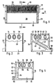
- FIG. 1 shows a longitudinal section through a the fin block of a heat exchanger and one Casting chamber forming casting
- Figure 2 shows a section through the casting along the line II-II Figure 1
- Figure 3 a Side view of the casting in the direction of arrow A in Figure 1 seen
- Figure 4 shows the other side view of the Cast part according to Figure 1.
- a casting 10 has three in a heat transfer area 12 water pipes 14, 16, 18 arranged in parallel next to one another which are provided with integrally molded ribs 20.
- the Water pipes 14, 16, 18 are at their entrances and exits connected in one piece by wall plates 22, 24, on those described in more detail below, for Water webs serving wall guides are provided.
- the Wall panels 22, 24 are over the heat transfer area 12 extended down to where they have side walls 26, 28 form a combustion chamber 30.
- the side walls 26, 28 are with a rear wall 32 and a front wall 34 of the combustion chamber 30 connected, which in turn until the Heat transfer area 12 pulled up and there to the Ribs 20 are formed.
- Two wall webs 36, 38 are formed on the wall plate 22, which together with a cover plate, not shown the two water pipes 14, 16 connecting chamber 40, and delimit a further chamber 42 into which the water pipe 18 flows.
- On the side wall 26 of the combustion chamber 30 are two Wall webs 44, 46 are formed, which are parallel at a distance are arranged to each other and delimit a channel 48. This connects the chamber 42 or the water pipe 18 with a connection 50 for a supply or discharge of the Pipes of heating water flowing through.
- Threaded holes 52 for screws for fastening the Cover plate are at different locations on the wall plate 22 Threaded holes 52 for screws for fastening the Cover plate provided.
- Two wall webs 54, 56 are formed on the wall plate 24, which together with a cover plate, not shown the chamber 58, connecting the two water pipes 16, 18 and delimit a further chamber 60 into which the water pipe 14 flows.
- On the side wall 28 of the combustion chamber 30 are two Wall webs 62, 64 formed parallel to one another at a distance, which delimit a channel 66 which connects the chamber 60 with a Connects connection 68 for a supply or discharge.
- the Wall plate 24 is also with threaded holes 70 for Screws for attaching the associated cover plate Mistake.
- the pipe passages and those between the wall bars on the Wall plates 22, 24 and the side walls 26, 28 of the Combustion chamber 30 recesses are formed by retractable slider, which from the sides in the The working area of the die casting tool protrudes.
- the sliders are easily according to the manufacturing requirements conical, so that the water pipes 14, 16, 18 from the end faces towards the middle slightly have increasing wall thickness.
- the fins 20 of the water pipes are characterized by a corresponding structure of an upper and realized a lower die casting tool part.
- the back wall 32 of the combustion chamber 30 and its front wall 34 protrude above a little beyond the ribs 20, where they hold a recording for form a flow protection.
Landscapes
- Engineering & Computer Science (AREA)
- Physics & Mathematics (AREA)
- Thermal Sciences (AREA)
- Chemical & Material Sciences (AREA)
- Combustion & Propulsion (AREA)
- Mechanical Engineering (AREA)
- General Engineering & Computer Science (AREA)
- Details Of Fluid Heaters (AREA)
- Gas Burners (AREA)
- Instantaneous Water Boilers, Portable Hot-Water Supply Apparatuses, And Control Of Portable Hot-Water Supply Apparatuses (AREA)
Abstract
Description
Claims (3)
- Gasbeheizter Wassererhitzer, mit einer Brennkammer und einem Wärmeübertrager, der nebeneinander angeordnete Wasserrohre mit am Außenumfang angeformten Rippen, die miteinander und mit zur Wasserführung an den Ein- und Ausgängen vorgesehenen Wandelementen als ein einstückiges Gußteil ausgebildet sind, dadurch gekennzeichnet, daß an das die Wasserrohre (14, 16, 18) bildende Gußteil (10) des Wärmeübertragers (12) auch mindestens die Rückwand (32) und die Seitenwände (26, 28) der Brennkammer (30) einstückig angeformt sind.
- Wassererhitzer nach Anspruch 1, dadurch gekennzeichnet, daß das Gußteil (10) des Wärmeübertragers (12) an den Ein- und Ausgängen der Wasserrohre (14, 16, 18) je eine die Wasserrohre verbindende Wandplatte (22, 24) hat, die zur Bildung von Wasserkammern (40, 42 bzw. 58, 60) mit Wandstegen (36, 38 bzw. 54, 56) und mit Mitteln (52 bzw. 70) zum Befestigen eines die Wasserkammer dicht abschließenden Deckels versehen sind.
- Wassererhitzer nach Anspruch 2, dadurch gekennzeichnet, daß jede Seitenwand (26, 28) der Brennkammer (30) mit Wandstegen (44, 46 bzw. 62, 64) zur Bildung eines Kanals (48 bzw. 66) versehen ist, welcher eine der Kammern (42 bzw. 60) mit einem Anschluß (50 bzw. 68) für eine externe Zu- bzw. Ableitung verbindet.
Applications Claiming Priority (2)
| Application Number | Priority Date | Filing Date | Title |
|---|---|---|---|
| DE19630509 | 1996-07-29 | ||
| DE19630509A DE19630509A1 (de) | 1996-07-29 | 1996-07-29 | Gasbeheizter Wassererhitzer |
Publications (3)
| Publication Number | Publication Date |
|---|---|
| EP0823599A2 true EP0823599A2 (de) | 1998-02-11 |
| EP0823599A3 EP0823599A3 (de) | 1999-03-10 |
| EP0823599B1 EP0823599B1 (de) | 2001-11-14 |
Family
ID=7801139
Family Applications (1)
| Application Number | Title | Priority Date | Filing Date |
|---|---|---|---|
| EP97109718A Expired - Lifetime EP0823599B1 (de) | 1996-07-29 | 1997-06-14 | Gasbeheizter Wassererhitzer |
Country Status (2)
| Country | Link |
|---|---|
| EP (1) | EP0823599B1 (de) |
| DE (2) | DE19630509A1 (de) |
Cited By (2)
| Publication number | Priority date | Publication date | Assignee | Title |
|---|---|---|---|---|
| EP1098148A3 (de) * | 1999-11-08 | 2003-01-22 | Joh. Vaillant GmbH u. Co. | Heizgerät |
| DE10200962A1 (de) * | 2002-01-12 | 2003-07-31 | Eberspaecher J Gmbh & Co | Heizgerät und Gehäuse für ein Heizgerät |
Citations (1)
| Publication number | Priority date | Publication date | Assignee | Title |
|---|---|---|---|---|
| EP0213792A2 (de) | 1985-08-08 | 1987-03-11 | Baxi Partnership Limited | Wärmetauscher |
Family Cites Families (2)
| Publication number | Priority date | Publication date | Assignee | Title |
|---|---|---|---|---|
| US4421066A (en) * | 1982-02-16 | 1983-12-20 | Teledyne Industries, Inc. | High efficiency boiler |
| US4501232A (en) * | 1983-10-03 | 1985-02-26 | Purex Pool Products, Inc. | Pool or spa water heater |
-
1996
- 1996-07-29 DE DE19630509A patent/DE19630509A1/de not_active Withdrawn
-
1997
- 1997-06-14 DE DE59705352T patent/DE59705352D1/de not_active Expired - Fee Related
- 1997-06-14 EP EP97109718A patent/EP0823599B1/de not_active Expired - Lifetime
Patent Citations (1)
| Publication number | Priority date | Publication date | Assignee | Title |
|---|---|---|---|---|
| EP0213792A2 (de) | 1985-08-08 | 1987-03-11 | Baxi Partnership Limited | Wärmetauscher |
Cited By (3)
| Publication number | Priority date | Publication date | Assignee | Title |
|---|---|---|---|---|
| EP1098148A3 (de) * | 1999-11-08 | 2003-01-22 | Joh. Vaillant GmbH u. Co. | Heizgerät |
| DE10200962A1 (de) * | 2002-01-12 | 2003-07-31 | Eberspaecher J Gmbh & Co | Heizgerät und Gehäuse für ein Heizgerät |
| US6712283B2 (en) | 2002-01-12 | 2004-03-30 | J. Eberspächer GmbH & Co. KG | Heating apparatus and housing for a heating apparatus |
Also Published As
| Publication number | Publication date |
|---|---|
| DE19630509A1 (de) | 1998-02-05 |
| EP0823599B1 (de) | 2001-11-14 |
| DE59705352D1 (de) | 2001-12-20 |
| EP0823599A3 (de) | 1999-03-10 |
Similar Documents
| Publication | Publication Date | Title |
|---|---|---|
| EP0653043B1 (de) | Wärmetauscher | |
| DE2615579A1 (de) | Waermetauscher | |
| DE3630084C2 (de) | ||
| DE19710069A1 (de) | Plattenheizkörper | |
| DE4313505A1 (de) | Flüssigkeitskühler in Scheibenbauweise | |
| DE3508834A1 (de) | Oelfilter mit integriertem waermetauscher | |
| DE112017001907T5 (de) | Energiewiedergewinnungseinheit für den Fahrzeuggebrauch | |
| DE3208097A1 (de) | Waermetauscher | |
| EP0823599B1 (de) | Gasbeheizter Wassererhitzer | |
| EP1757887B1 (de) | Wärmetauscherblock | |
| DE3421746C2 (de) | Wärmeaustauscher | |
| DE4105232C1 (de) | ||
| DE10041121B4 (de) | Wärmeübertrager mit mehreren Wärmeübertragungskreisen | |
| EP2085732B1 (de) | Glaswärmetauscher mit Kunststoffrohrboden | |
| DE102004004895B3 (de) | Wärmeübertrager aus runden profilierten Wärmeübertragungsplatten | |
| EP0905453B2 (de) | Brauchwasserbereiter | |
| DE3926303A1 (de) | Abgasduese | |
| DE2542683C3 (de) | Gegenstrom-Wärmetauscher mit einem Kern aus übereinander angeordneten Plattenbauteilen | |
| EP0197169B1 (de) | Ölkühler | |
| DE3007168C2 (de) | Flüssigkeitsgekühlte Halbleitersäule | |
| DE69801631T2 (de) | Wärmetauscherelement mit hohem Wirkungsgrad für einen Heizkörper in einem Gliederheizkessel | |
| DE10011791B4 (de) | Fluidgekühltes Mittelbalkenelement für mehrbahnige Verbrennungsroste und Mittelbalken | |
| DE540204C (de) | Heizkoerper fuer Verdampfer | |
| DE3624394C2 (de) | Heizkörper | |
| DE102004008967B3 (de) | Sonnenkollektor |
Legal Events
| Date | Code | Title | Description |
|---|---|---|---|
| PUAI | Public reference made under article 153(3) epc to a published international application that has entered the european phase |
Free format text: ORIGINAL CODE: 0009012 |
|
| AK | Designated contracting states |
Kind code of ref document: A2 Designated state(s): DE FR GB IT |
|
| PUAL | Search report despatched |
Free format text: ORIGINAL CODE: 0009013 |
|
| AK | Designated contracting states |
Kind code of ref document: A3 Designated state(s): AT BE CH DE DK ES FI FR GB GR IE IT LI LU MC NL PT SE |
|
| 17P | Request for examination filed |
Effective date: 19990910 |
|
| AKX | Designation fees paid |
Free format text: DE FR GB IT |
|
| GRAG | Despatch of communication of intention to grant |
Free format text: ORIGINAL CODE: EPIDOS AGRA |
|
| 17Q | First examination report despatched |
Effective date: 20010227 |
|
| GRAG | Despatch of communication of intention to grant |
Free format text: ORIGINAL CODE: EPIDOS AGRA |
|
| GRAH | Despatch of communication of intention to grant a patent |
Free format text: ORIGINAL CODE: EPIDOS IGRA |
|
| GRAH | Despatch of communication of intention to grant a patent |
Free format text: ORIGINAL CODE: EPIDOS IGRA |
|
| GRAA | (expected) grant |
Free format text: ORIGINAL CODE: 0009210 |
|
| AK | Designated contracting states |
Kind code of ref document: B1 Designated state(s): DE FR GB IT |
|
| REF | Corresponds to: |
Ref document number: 59705352 Country of ref document: DE Date of ref document: 20011220 |
|
| REG | Reference to a national code |
Ref country code: GB Ref legal event code: IF02 |
|
| GBT | Gb: translation of ep patent filed (gb section 77(6)(a)/1977) |
Effective date: 20020117 |
|
| ET | Fr: translation filed | ||
| PGFP | Annual fee paid to national office [announced via postgrant information from national office to epo] |
Ref country code: GB Payment date: 20020527 Year of fee payment: 6 |
|
| PGFP | Annual fee paid to national office [announced via postgrant information from national office to epo] |
Ref country code: FR Payment date: 20020622 Year of fee payment: 6 |
|
| PLBE | No opposition filed within time limit |
Free format text: ORIGINAL CODE: 0009261 |
|
| STAA | Information on the status of an ep patent application or granted ep patent |
Free format text: STATUS: NO OPPOSITION FILED WITHIN TIME LIMIT |
|
| 26N | No opposition filed | ||
| PG25 | Lapsed in a contracting state [announced via postgrant information from national office to epo] |
Ref country code: DE Free format text: LAPSE BECAUSE OF NON-PAYMENT OF DUE FEES Effective date: 20030101 |
|
| PG25 | Lapsed in a contracting state [announced via postgrant information from national office to epo] |
Ref country code: GB Free format text: LAPSE BECAUSE OF NON-PAYMENT OF DUE FEES Effective date: 20030614 |
|
| GBPC | Gb: european patent ceased through non-payment of renewal fee |
Effective date: 20030614 |
|
| PG25 | Lapsed in a contracting state [announced via postgrant information from national office to epo] |
Ref country code: FR Free format text: LAPSE BECAUSE OF NON-PAYMENT OF DUE FEES Effective date: 20040227 |
|
| REG | Reference to a national code |
Ref country code: FR Ref legal event code: ST |
|
| PG25 | Lapsed in a contracting state [announced via postgrant information from national office to epo] |
Ref country code: IT Free format text: LAPSE BECAUSE OF NON-PAYMENT OF DUE FEES;WARNING: LAPSES OF ITALIAN PATENTS WITH EFFECTIVE DATE BEFORE 2007 MAY HAVE OCCURRED AT ANY TIME BEFORE 2007. THE CORRECT EFFECTIVE DATE MAY BE DIFFERENT FROM THE ONE RECORDED. Effective date: 20050614 |