EP0823623B1 - Verfahren zur Ermittlung von Reifendefekten - Google Patents
Verfahren zur Ermittlung von Reifendefekten Download PDFInfo
- Publication number
- EP0823623B1 EP0823623B1 EP96112685A EP96112685A EP0823623B1 EP 0823623 B1 EP0823623 B1 EP 0823623B1 EP 96112685 A EP96112685 A EP 96112685A EP 96112685 A EP96112685 A EP 96112685A EP 0823623 B1 EP0823623 B1 EP 0823623B1
- Authority
- EP
- European Patent Office
- Prior art keywords
- tyre
- grey
- value
- image
- tire
- Prior art date
- Legal status (The legal status is an assumption and is not a legal conclusion. Google has not performed a legal analysis and makes no representation as to the accuracy of the status listed.)
- Expired - Lifetime
Links
- 238000000034 method Methods 0.000 title claims description 32
- 230000007547 defect Effects 0.000 title claims description 24
- 238000011156 evaluation Methods 0.000 claims description 20
- 238000012360 testing method Methods 0.000 claims description 15
- 230000005855 radiation Effects 0.000 claims description 10
- 238000012545 processing Methods 0.000 claims description 4
- 230000008859 change Effects 0.000 claims description 3
- 230000003287 optical effect Effects 0.000 claims description 3
- 230000001427 coherent effect Effects 0.000 claims description 2
- 238000003384 imaging method Methods 0.000 claims description 2
- 238000006073 displacement reaction Methods 0.000 claims 1
- 238000005728 strengthening Methods 0.000 claims 1
- 238000012956 testing procedure Methods 0.000 claims 1
- 238000010008 shearing Methods 0.000 description 15
- 238000009826 distribution Methods 0.000 description 14
- 238000001514 detection method Methods 0.000 description 4
- 230000000694 effects Effects 0.000 description 4
- 229910000831 Steel Inorganic materials 0.000 description 3
- 230000008569 process Effects 0.000 description 3
- 239000010959 steel Substances 0.000 description 3
- 230000007704 transition Effects 0.000 description 3
- 238000011161 development Methods 0.000 description 2
- 230000003993 interaction Effects 0.000 description 2
- 230000002787 reinforcement Effects 0.000 description 2
- 238000012935 Averaging Methods 0.000 description 1
- 230000005856 abnormality Effects 0.000 description 1
- 238000006243 chemical reaction Methods 0.000 description 1
- 238000010276 construction Methods 0.000 description 1
- 238000013461 design Methods 0.000 description 1
- 230000004069 differentiation Effects 0.000 description 1
- 238000005286 illumination Methods 0.000 description 1
- 238000010606 normalization Methods 0.000 description 1
Images


Classifications
-
- G—PHYSICS
- G01—MEASURING; TESTING
- G01M—TESTING STATIC OR DYNAMIC BALANCE OF MACHINES OR STRUCTURES; TESTING OF STRUCTURES OR APPARATUS, NOT OTHERWISE PROVIDED FOR
- G01M17/00—Testing of vehicles
- G01M17/007—Wheeled or endless-tracked vehicles
- G01M17/02—Tyres
- G01M17/027—Tyres using light, e.g. infrared, ultraviolet or holographic techniques
Definitions
- the invention relates to a method for determining Tire defects, preferably in truck tires, after Preamble of claim 1.
- a method is known from DE-OS-42 31 578 A1, at the side wall of a tire using several light-emitting diodes irradiated with coherent light and by that Tire backscattered radiation in two partial radiations is divided.
- the two partial radiations become like this reunited that the two partial radiations are slightly offset from each other (shearing).
- the the Partial radiations carrying image information become one supplied electronic image sensor system.
- the on the Radiation impinging image sensor is after a A / D conversion converted into digital signals. Before the The tire is initially tested with a predetermined one Inflated pressure.
- DE-OS-42 31 578 A1 To improve the known from DE-OS-42 31 578 A1 The process is proposed in DE 195 01 073 A1, preferably according to the method of DE-OS-42 31 578 A1 by tangential shearing in the circumferential direction of the Tire (more precisely through a shearing in one too a radial direction of the tire) and steady output grayscale image in the way to differentiate partially that a second the output gray scale image same gray value image is generated, and this against the output gray scale image in the shearing direction is geometrically shifted and manipulated in this way Second gray value image subtracted from the output gray value image so that a resulting grayscale image arises.
- Truck tires have a multi-layer steel belt package that has its own Represents reinforcement.
- the carcass provides one of the belt packs with its steel mesh insert largely independent reinforcement. There are therefore hardly any interactions between the belt package and the carcass in terms of strength.
- the highest Tensions arise in the shoulder area in the transition zone belt package and carcass. It happens there from extreme loads or damage to detach of the belt package. These replacements can hardly be done from the outside can be detected.
- the invention has for its object a method to create tires with which you can also test Belt edge detachments for truck tires and other tires, where the belt and carcass are largely independent Strengths are, reliably recorded.
- This task is accomplished by a method with the characteristics of claim 1 solved.
- the output gray-scale image becomes determined with the help of a deformation that by changing the pressure, preferably by lowering the pressure tire pressure is reached.
- a drop in pressure can the belt edge of a truck tire as Clamping point can be viewed.
- the deformations therefore correspond approximately to the deformations of a beam clamped on one side a force at a distance from the clamping point Body is applied.
- the method according to the invention is then not only for the detection of tire defects in the Shoulder area of truck tires but also for detection of defects in all areas of a tire who have a relationship of patronage, which one unilaterally clamped carrier are similar.
- the deformation can also be achieved by increasing the pressure.
- Fig. 1 shows schematically the cross section of a test Truck tire 10 with a carcass 13 containing steel mesh, a tread 11 and one between the carcass 13 and of the tread 11 arranged belt package 12.
- Fig. 2 a test section which is circular with respect to the tire axis 15 of the side wall 14 of the truck tire 10 shown, the upper Edge in the area of the transition between carcass 13 and Belt package 12 is located.
- the Test area 15 initially by means of from DE-OS-42 31 578 A1 known method checked, in which several laser diodes for Illumination can be used and the shearing in radial Direction of the truck tire, i.e. 2 from top to bottom he follows.
- the deformation occurs because the tire pressure is reduced, whereby the sidewall 14 of the tire by Line Q in the transition area between carcass 13 and belt package 12 is moved inwards.
- the deformation corresponds therefore approximately the deformation of a one-sided clamped Carrier.
- a modulo-2 ⁇ image is obtained, which thus becomes an output gray-scale image is implemented that the gray values of the individual Pixels the difference in the deformation of two points on the Specify the test object on a radial or on the radial parallel straight lines are adjacent.
- Suitable development methods for this are described for example in “Digital Processing and evaluation of interference images”, Wolfgang Osten, Akademieverlag Berlin, 1991, pp. 138 to 144 and in “Proceedings of the First International Workshop on Automatic Processing of Fringe Patterns ", Akademieverlag Berlin, 1989, Pp. 23 to 31.
- a narrow circular arc-shaped strip of the output gray-scale image which is a narrow circular arc Strips 16 on the outer edge of the test area 15 of the Side wall 14 with a width S of 5 mm, for example corresponds, in the computer a mean gray value by known Methods of averaging determined. Doing so each pixel in the strip of the output gray scale image a certain gray value from a gray value range of 0 (black) and 255 (white). Then the Grayscale values of all pixels in the narrow strip added and divided the sum by the number of pixels.
- the average determined in this way is then in the computer Gray value from a predetermined reference gray value, e.g. subtracted from the gray value 128. Now the in the computer Result of the subtraction corresponding gray value, which too can be negative to the gray values of the individual pixels of the output gray-scale image is added, whereby an evaluation gray-scale image is obtained.
- FIG. 3 shows the evaluation grayscale image of a truck tire, that has no defect in the test area.
- 4 are the gray value distributions of the evaluation gray value image of Fig. 3 along two parallel to the radial Lines I and II shown. It can be clearly seen that the two gray value distributions are approximately the same Level, both gray value distributions below of a threshold gray value SW, based on which a Tire defect is determined.
- FIG. 5 shows the evaluation grayscale image of a truck tire with a tire defect F on the straight line I, for example caused by a detachment in the area of the belt edge has been.
- Fig. 6 it can be clearly seen that the gray level the gray value distribution along the straight line I clearly above the gray value level along the gray value distribution the straight line II, along which there is no tire defect is available.
- the gray value distribution I exceeds in the right area Fig. 6, i.e. the area of the tire defect the threshold gray value SW, which indicates an error.
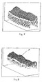
- FIG. 7 and 8 show a three-dimensional representation of the Gray value distributions of the evaluation gray value images from FIG. 3. It can clearly be seen that the gray value distribution of Fig. 8 in the area of the tire defect F a hill-like Has increase, which indicates the tire defect F.
- a suitable threshold gray value, which is exceeded by a Tire defect indicates, for example, 180.
- the threshold depends on the test parameters, e.g. the Shearing distance, air lowering or the type of tire.
- the evaluation grayscale image when a tire defect is detected exceeds the threshold gray value, for example a signal is emitted by the computer, which is a horn signal a horn device or an optical signal optical display triggers, causing an operator to carries out the method according to the invention in a simple manner a tire defect can be indicated. After triggering the whole process can be stopped because the tested truck tires unsuitable for further processing is.
- the threshold gray value for example a signal is emitted by the computer, which is a horn signal a horn device or an optical signal optical display triggers, causing an operator to carries out the method according to the invention in a simple manner a tire defect can be indicated. After triggering the whole process can be stopped because the tested truck tires unsuitable for further processing is.
Landscapes
- Physics & Mathematics (AREA)
- General Physics & Mathematics (AREA)
- Length Measuring Devices By Optical Means (AREA)
- Tires In General (AREA)
- Image Processing (AREA)
Priority Applications (3)
| Application Number | Priority Date | Filing Date | Title |
|---|---|---|---|
| ES96112685T ES2188696T3 (es) | 1996-08-06 | 1996-08-06 | Procedimiento para detectar los defectos de los neumaticos. |
| EP96112685A EP0823623B1 (de) | 1996-08-06 | 1996-08-06 | Verfahren zur Ermittlung von Reifendefekten |
| DE59609853T DE59609853D1 (de) | 1996-08-06 | 1996-08-06 | Verfahren zur Ermittlung von Reifendefekten |
Applications Claiming Priority (1)
| Application Number | Priority Date | Filing Date | Title |
|---|---|---|---|
| EP96112685A EP0823623B1 (de) | 1996-08-06 | 1996-08-06 | Verfahren zur Ermittlung von Reifendefekten |
Publications (2)
| Publication Number | Publication Date |
|---|---|
| EP0823623A1 EP0823623A1 (de) | 1998-02-11 |
| EP0823623B1 true EP0823623B1 (de) | 2002-11-06 |
Family
ID=8223082
Family Applications (1)
| Application Number | Title | Priority Date | Filing Date |
|---|---|---|---|
| EP96112685A Expired - Lifetime EP0823623B1 (de) | 1996-08-06 | 1996-08-06 | Verfahren zur Ermittlung von Reifendefekten |
Country Status (3)
| Country | Link |
|---|---|
| EP (1) | EP0823623B1 (es) |
| DE (1) | DE59609853D1 (es) |
| ES (1) | ES2188696T3 (es) |
Families Citing this family (10)
| Publication number | Priority date | Publication date | Assignee | Title |
|---|---|---|---|---|
| EP0955532A3 (de) * | 1998-05-07 | 2000-02-02 | Nova C.O.R.D. Ag | Optoelektronisches Strukturfestigkeitsprüfverfahren mit Störungserkennung |
| EP0955533A3 (de) * | 1998-05-07 | 2000-02-02 | Nova C.O.R.D. Ag | Verfahren zur Strukturfestigkeitsprüfung von Reifen, vorzugsweise von LKW-Reifen |
| DE19944314C2 (de) * | 1999-09-03 | 2003-03-13 | Steinbichler Optotechnik Gmbh | Prüfgerät für Reifen |
| EP1043578B1 (de) | 1999-04-09 | 2004-10-13 | Steinbichler Optotechnik Gmbh | Optisches Prüfgerät für Reifen |
| DE19922775A1 (de) * | 1999-05-18 | 2000-11-23 | Beissbarth Gmbh | Reifenprüfverfahren |
| DE10019387C2 (de) * | 2000-04-19 | 2003-05-15 | Bernward Maehner | Verfahren und Vorrichtung zur Untersuchung von Reifen |
| DE10019386C2 (de) | 2000-04-19 | 2003-04-03 | Bernward Maehner | Verfahren und Vorrichtung zur Prüfung von Reifen |
| DE10102232C2 (de) * | 2001-01-19 | 2002-11-07 | Stefan Dengler | Reifenprüfeinrichtung und Reifenprüfverfahren |
| CN113516608B (zh) * | 2020-03-26 | 2024-03-26 | 合肥美亚光电技术股份有限公司 | 轮胎的缺陷检测方法和检测装置、轮胎检测设备 |
| CN113673542B (zh) * | 2021-10-23 | 2022-02-08 | 深圳希研工业科技有限公司 | 基于物联网的快递包裹破损识别方法及系统 |
Citations (1)
| Publication number | Priority date | Publication date | Assignee | Title |
|---|---|---|---|---|
| DE19501073A1 (de) * | 1995-01-16 | 1996-08-01 | Nova C O R D Ag | Bildverarbeitungsverfahren zur Ermittlung der Strukturfestigkeit eines Prüfobjektes mit diffus streuender Oberfläche |
Family Cites Families (1)
| Publication number | Priority date | Publication date | Assignee | Title |
|---|---|---|---|---|
| DE4231578C2 (de) * | 1992-09-21 | 1995-06-29 | Nova C O R D Ag | Verfahren zur Ermittlung von Verformungen an einem Prüfobjekt mit diffus streuender Oberfläche, insbesondere an Reifen, sowie Vorrichtung zur Durchführung des Verfahrens |
-
1996
- 1996-08-06 ES ES96112685T patent/ES2188696T3/es not_active Expired - Lifetime
- 1996-08-06 EP EP96112685A patent/EP0823623B1/de not_active Expired - Lifetime
- 1996-08-06 DE DE59609853T patent/DE59609853D1/de not_active Expired - Fee Related
Patent Citations (1)
| Publication number | Priority date | Publication date | Assignee | Title |
|---|---|---|---|---|
| DE19501073A1 (de) * | 1995-01-16 | 1996-08-01 | Nova C O R D Ag | Bildverarbeitungsverfahren zur Ermittlung der Strukturfestigkeit eines Prüfobjektes mit diffus streuender Oberfläche |
Also Published As
| Publication number | Publication date |
|---|---|
| EP0823623A1 (de) | 1998-02-11 |
| DE59609853D1 (de) | 2002-12-12 |
| ES2188696T3 (es) | 2003-07-01 |
Similar Documents
| Publication | Publication Date | Title |
|---|---|---|
| DE69021207T2 (de) | Einrichtung zum gleisgebundenen erfassen des radprofiles von rädern eines zuges. | |
| EP2732236B1 (de) | Optische vorrichtung und verfahren zur reifenprüfung | |
| EP1332334B1 (de) | Messeinrichtung zur berührungslosen messung von reifen | |
| DE102008037356B4 (de) | Prüfanlage und Verfahren zum Prüfen von Reifen | |
| EP1519188B1 (de) | Vorrichtung und Verfahren zur Qualitätsprüfung eines Körpers | |
| WO1999004248A1 (de) | Verfahren zur automatischen erkennung von oberflächenfehlern an rohkarosserien und vorrichtung zur durchführung des verfahrens | |
| EP4416459B1 (de) | Verfahren zum prüfen von reifen | |
| DE69014505T2 (de) | System zur optischen Inspektion von Bedingungen von Teilen, die auf einem Substrat angebracht sind. | |
| EP0823623B1 (de) | Verfahren zur Ermittlung von Reifendefekten | |
| EP1245923A2 (de) | Verfahren und Vorrichtung zur Kantenverfolgung und Kantenprüfung | |
| EP2850386A1 (de) | Verfahren und vorrichtung zur inspektion von oberflächen eines untersuchten objekts | |
| DE10110994B4 (de) | Vorrichtung zur Bildabtastung eines Objektes | |
| EP1647817A2 (de) | Verfahren und Vorrichtung zur optischen Prüfung der Oberfläche eines Reifens | |
| DE19501073A1 (de) | Bildverarbeitungsverfahren zur Ermittlung der Strukturfestigkeit eines Prüfobjektes mit diffus streuender Oberfläche | |
| EP2199735A2 (de) | Verfahren zur berührungslosen dynamischen Erfassung des Durchmessers eines Schienenfahrzeugrades | |
| DE3433024C2 (de) | Verfahren und Vorrichtung zum Fehlerprüfen von Photomasken | |
| DE2613594B2 (de) | Verfahren und vorrichtung zur bestimmung der begrenzung des von einem kraftfahrzeug-scheinwerfer ausgestrahlten lichtbuendels | |
| DE602004001909T2 (de) | Verfahren und Instrument zur Kontrolle der Verbindung von Wänden einer wabenförmigen Struktur mit einem Substrat | |
| DE102023004314A1 (de) | Verfahren und Vorrichtung zur Zustandsüberwachung mindestens eines Fahrzeugreifens an einem Fahrzeug | |
| EP0647480A1 (de) | Verfahren zum Ausscheiden von Mehrwegflaschen aus dem Mehrwegumlauf | |
| EP0617256B1 (de) | Verfahren zur Ermittlung eines Durchmessers einer Umfangslinie an Rädern von Radsätzen und Einrichtung zur Durchführung des Verfahrens | |
| DE102016112712A1 (de) | Verfahren zur Bestimmung von Parametern der Fahrwerkgeometrie von Rädern einer nicht gelenkten Achse, Verwendung des Verfahrens, Prüfstand für ein Fahrzeug sowie eine Messeinheit | |
| DE102021118449B3 (de) | Vorrichtung und Verfahren zur Bildaufnahme eines Reifens eines Fahrzeugs | |
| EP0955532A2 (de) | Optoelektronisches Strukturfestigkeitsprüfverfahren mit Störungserkennung | |
| DE102022126613A1 (de) | Verfahren zum Prüfen von Reifen |
Legal Events
| Date | Code | Title | Description |
|---|---|---|---|
| PUAI | Public reference made under article 153(3) epc to a published international application that has entered the european phase |
Free format text: ORIGINAL CODE: 0009012 |
|
| AK | Designated contracting states |
Kind code of ref document: A1 Designated state(s): DE ES FR GB IT |
|
| 17P | Request for examination filed |
Effective date: 19980720 |
|
| AKX | Designation fees paid |
Free format text: DE ES FR GB IT |
|
| RBV | Designated contracting states (corrected) |
Designated state(s): DE ES FR GB IT |
|
| 17Q | First examination report despatched |
Effective date: 20010523 |
|
| GRAG | Despatch of communication of intention to grant |
Free format text: ORIGINAL CODE: EPIDOS AGRA |
|
| GRAG | Despatch of communication of intention to grant |
Free format text: ORIGINAL CODE: EPIDOS AGRA |
|
| GRAH | Despatch of communication of intention to grant a patent |
Free format text: ORIGINAL CODE: EPIDOS IGRA |
|
| GRAH | Despatch of communication of intention to grant a patent |
Free format text: ORIGINAL CODE: EPIDOS IGRA |
|
| GRAA | (expected) grant |
Free format text: ORIGINAL CODE: 0009210 |
|
| AK | Designated contracting states |
Kind code of ref document: B1 Designated state(s): DE ES FR GB IT |
|
| REG | Reference to a national code |
Ref country code: GB Ref legal event code: FG4D Free format text: NOT ENGLISH |
|
| REF | Corresponds to: |
Ref document number: 59609853 Country of ref document: DE Date of ref document: 20021212 |
|
| GBT | Gb: translation of ep patent filed (gb section 77(6)(a)/1977) |
Effective date: 20030315 |
|
| ET | Fr: translation filed | ||
| REG | Reference to a national code |
Ref country code: ES Ref legal event code: FG2A Ref document number: 2188696 Country of ref document: ES Kind code of ref document: T3 |
|
| PG25 | Lapsed in a contracting state [announced via postgrant information from national office to epo] |
Ref country code: GB Free format text: LAPSE BECAUSE OF NON-PAYMENT OF DUE FEES Effective date: 20030806 |
|
| PG25 | Lapsed in a contracting state [announced via postgrant information from national office to epo] |
Ref country code: ES Free format text: LAPSE BECAUSE OF NON-PAYMENT OF DUE FEES Effective date: 20030807 |
|
| PLBE | No opposition filed within time limit |
Free format text: ORIGINAL CODE: 0009261 |
|
| STAA | Information on the status of an ep patent application or granted ep patent |
Free format text: STATUS: NO OPPOSITION FILED WITHIN TIME LIMIT |
|
| 26N | No opposition filed |
Effective date: 20030807 |
|
| GBPC | Gb: european patent ceased through non-payment of renewal fee |
Effective date: 20030806 |
|
| PG25 | Lapsed in a contracting state [announced via postgrant information from national office to epo] |
Ref country code: FR Free format text: LAPSE BECAUSE OF NON-PAYMENT OF DUE FEES Effective date: 20040430 |
|
| REG | Reference to a national code |
Ref country code: FR Ref legal event code: ST |
|
| PGFP | Annual fee paid to national office [announced via postgrant information from national office to epo] |
Ref country code: DE Payment date: 20040929 Year of fee payment: 9 |
|
| REG | Reference to a national code |
Ref country code: ES Ref legal event code: FD2A Effective date: 20030807 |
|
| PG25 | Lapsed in a contracting state [announced via postgrant information from national office to epo] |
Ref country code: IT Free format text: LAPSE BECAUSE OF NON-PAYMENT OF DUE FEES Effective date: 20050806 |
|
| PG25 | Lapsed in a contracting state [announced via postgrant information from national office to epo] |
Ref country code: DE Free format text: LAPSE BECAUSE OF NON-PAYMENT OF DUE FEES Effective date: 20060301 |