EP0823628A2 - Optischer Sensor - Google Patents
Optischer Sensor Download PDFInfo
- Publication number
- EP0823628A2 EP0823628A2 EP97113077A EP97113077A EP0823628A2 EP 0823628 A2 EP0823628 A2 EP 0823628A2 EP 97113077 A EP97113077 A EP 97113077A EP 97113077 A EP97113077 A EP 97113077A EP 0823628 A2 EP0823628 A2 EP 0823628A2
- Authority
- EP
- European Patent Office
- Prior art keywords
- sensor
- optical
- cavity
- transmitting
- flange
- Prior art date
- Legal status (The legal status is an assumption and is not a legal conclusion. Google has not performed a legal analysis and makes no representation as to the accuracy of the status listed.)
- Ceased
Links
Images



Classifications
-
- G—PHYSICS
- G01—MEASURING; TESTING
- G01N—INVESTIGATING OR ANALYSING MATERIALS BY DETERMINING THEIR CHEMICAL OR PHYSICAL PROPERTIES
- G01N21/00—Investigating or analysing materials by the use of optical means, i.e. using sub-millimetre waves, infrared, visible or ultraviolet light
- G01N21/17—Systems in which incident light is modified in accordance with the properties of the material investigated
- G01N21/47—Scattering, i.e. diffuse reflection
- G01N21/49—Scattering, i.e. diffuse reflection within a body or fluid
- G01N21/53—Scattering, i.e. diffuse reflection within a body or fluid within a flowing fluid, e.g. smoke
- G01N21/534—Scattering, i.e. diffuse reflection within a body or fluid within a flowing fluid, e.g. smoke by measuring transmission alone, i.e. determining opacity
-
- A—HUMAN NECESSITIES
- A47—FURNITURE; DOMESTIC ARTICLES OR APPLIANCES; COFFEE MILLS; SPICE MILLS; SUCTION CLEANERS IN GENERAL
- A47L—DOMESTIC WASHING OR CLEANING; SUCTION CLEANERS IN GENERAL
- A47L15/00—Washing or rinsing machines for crockery or tableware
- A47L15/42—Details
- A47L15/4297—Arrangements for detecting or measuring the condition of the washing water, e.g. turbidity
-
- D—TEXTILES; PAPER
- D06—TREATMENT OF TEXTILES OR THE LIKE; LAUNDERING; FLEXIBLE MATERIALS NOT OTHERWISE PROVIDED FOR
- D06F—LAUNDERING, DRYING, IRONING, PRESSING OR FOLDING TEXTILE ARTICLES
- D06F34/00—Details of control systems for washing machines, washer-dryers or laundry dryers
- D06F34/14—Arrangements for detecting or measuring specific parameters
- D06F34/22—Condition of the washing liquid, e.g. turbidity
-
- G—PHYSICS
- G01—MEASURING; TESTING
- G01N—INVESTIGATING OR ANALYSING MATERIALS BY DETERMINING THEIR CHEMICAL OR PHYSICAL PROPERTIES
- G01N21/00—Investigating or analysing materials by the use of optical means, i.e. using sub-millimetre waves, infrared, visible or ultraviolet light
- G01N21/84—Systems specially adapted for particular applications
- G01N21/85—Investigating moving fluids or granular solids
- G01N21/8507—Probe photometers, i.e. with optical measuring part dipped into fluid sample
-
- D—TEXTILES; PAPER
- D06—TREATMENT OF TEXTILES OR THE LIKE; LAUNDERING; FLEXIBLE MATERIALS NOT OTHERWISE PROVIDED FOR
- D06F—LAUNDERING, DRYING, IRONING, PRESSING OR FOLDING TEXTILE ARTICLES
- D06F2103/00—Parameters monitored or detected for the control of domestic laundry washing machines, washer-dryers or laundry dryers
- D06F2103/20—Washing liquid condition, e.g. turbidity
- D06F2103/22—Content of detergent or additives
Definitions
- the invention relates to an optical sensor used for the detection of optical Signals in an environment is designed, the components of the sensor largely should be tightly shielded from the environment and the sensor against the Properties of the surrounding medium, such as. B. the temperature, chemical aggressiveness etc., should be largely protected.
- Such a medium is, for example, the washing liquor of a washing machine or Dishwasher detergent solution.
- optical sensors for determining the turbidity of the Wash or rinse water used From the detected signals, i.e. H. from the measured Cloudiness of the lye can draw conclusions for the further washing or rinsing process, especially about the need for fresh water, the degree of purity of the Laundry or dishes etc. are pulled.
- the turbidity of a wash liquor is determined by an optical sensor in the Rule in transmitted light or absorbance measurement. With the optical described below Scattered light measurement is also possible.
- transmitted light or absorbance measurement is that emitted by a transmitter and attenuated by the wash liquor Light detected by a receiver.
- To attenuate the transmitted light mainly carry out scattering and absorption processes of the dissolved or dispersed substances.
- transmitter units in the near infrared The area shows that dyeing of the lye usually counteracts the cloudiness caused by the Detergents are negligible.
- the object of the invention is to provide an optical sensor that protects against external influences is largely protected.
- optical sensor consisting of a transmitting and receiving part there, at least the transmitting or receiving part a means for light emission or detection, which is introduced into a cavity which with a optically transparent object is completed.
- the transmitting part with a collimating and / or the receiving part be completed with a focusing object.
- the collimating or focusing Object spherical represents the the most economical and simplest form of a collimating or focusing lens. In terms of assembly technology, it can also be easily and tightly sealed to one that is to be detected Complete the medium.
- the cavity is formed by a tube.
- the means for Record and shield light emission and detection particularly well and by appropriate Bring the pipe to the desired measuring point.
- An optical waveguide is particularly suitable, in particular lets, as a means for light emission simply insert an optical fiber into a thin tube.
- An optimal efficiency of the sensor can be achieved if the optical fiber is spaced from the spherical object.
- the means for light emission or detection do not necessarily have to be an optical waveguide have, but could directly include a light emitting diode in front of the collimating optical object, for example a glass ball, are arranged.
- the electrical connections of this photodiode would then have to go through the cavity, for example through the pipe, are led to the outside.
- this is disadvantageous as the photodiodes are in the cavity around which the medium flows and are therefore more exposed to temperature fluctuations or other influences, as if they were outside the medium to be measured.
- the cavity of the transmitting and receiving part is connected to a flange that The transmitter and receiver are accessible on the connection side and the sensor by means of the flange can be introduced tightly into a medium to be detected.
- the light emitting diodes or in general the means that the optical signals in convert electrical and vice versa, outside of the room in which to be detected Medium is located are arranged and are therefore absolutely separate from influences caused by the medium.
- the converter units outside the vat for example in the other control units of the Have the device integrated.
- the supply line can be connected via an optical fiber Connection to be introduced into the tub.
- the optical fibers can be outside the Vats can already be laid in a pipe or freely.
- a separate connection for the sensor can be made, for example, via a screw connection or another medium-tight connection can be provided.
- the means for light emission or detection can be particularly advantageously by means of a Pipe over the flange of a heating element of a washing machine or dishwasher in insert the tub so that only the flange of the heating element is designed accordingly must be, but no special additional opening in the tub got to.
- the sensor arrangement is designed so that at least two sensors are different have long measuring distances, aging, pollution, remaining Temperature and possible other influences affecting the performance of the sensor compensate in the sensor arrangement.
- two sensors can work together connected that they mechanically stabilize each other.
- the sensors are operated with different wavelengths, of which at least one is in the visible spectral range, so it can also be different Detect the color of the medium.
- a transmitting part can be used that can be operated with different wavelengths. Leave with it detect the color of the medium with just one sensor.
- the integration of the optical sensor in a heating element is one Household appliance particularly advantageous. But this does not only apply to the previous ones Characteristics defined sensor, but in general on a sensor for turbidity measurement, regardless of its structure, too.
- Fig. 1 shows a means for light emission, which, for example, in a cavity HR can be formed by a tube is introduced.
- a - serves as a means of light emission partially shown - optical fiber LW.
- the end of the optical fiber LW is in Distance d to a collimating or focusing optical object.
- this object is a glass ball GK.
- the light bundle L leaves the optical fiber LF at an opening angle phi collimates through the glass ball GK and strikes the object to be detected as a parallel light beam Medium.
- the diameter and the position of the glass ball GK is based on the numerical Adjust the aperture of the optical fiber. The means or calculation methods for this are well known to the person skilled in the art.
- the distance between the glass ball GK or more precisely between the object-side main plane of the spherical optics and the fiber LF correspond to the object-side focal length of the spherical optics.
- the numerical aperture of the Fiber should be selected so that the sphere is illuminated as completely as possible at this distance is.
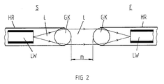
- the receiver E is constructed in the same way as the transmitter S.
- the glass ball GK is used at the receiver E to focus the parallel light beam L.
- the cavity HR of the receiver or the transmitter could also be, for example Rectangle or the means for light detection or the means for light emission could integrated into an existing housing of a wash tub or a rinsing container will;
- the optical waveguide LW could be by another means, for example be replaced by a light-emitting diode etc.
- the measuring section is between the two glass spheres GK of the transmitter and receiver.
- Fig. 3 shows an optical sensor with a transmitting and receiving part S, E, which in one Heating element of a household appliance, for example a washing machine or a dishwasher, can be used.
- the heating element consists of a flange FL, the one Seal D for the water- or alkali-tight closure of the tub or rinsing container having.
- the heating elements HS in - shown only partially here - are flanged over the flange introduced the vat.
- the Flange FL designed to receive a metal pipe MR.
- the LW fiber optic cables can thus from the outside into the metal tube or tubes of the transmitter S and the receiver E. be introduced.
- the metal tube MR of the transmitter S and the receiver E are each completed with glass balls GK.
- the measuring section is located between the glass spheres GK m. From the outside, i.e. H. from the one facing away from the heating element and the sensor
- the optical fibers LW are guided to a circuit board LP and there to the converter units, d. H. to a transmitter diode SD and a receiver diode ED, connected.
- the transmitter diode SD and the receiver diode ED have input and output sides electrical connections A on. There are others on the circuit board - shown in broken lines Transmitter and receiver diodes are provided, since the washing or Rinsing liquor can also be used in a sensor arrangement with several optical sensors can.
- FIG. 4 A sensor arrangement with two optical sensors is shown in FIG. 4.
- the transmitting and receiving means are not above the Heating rod flange but connected via a separate threaded flange GF.
- the measuring section m1 is shorter than the measuring section m2. Because of the different Lengths of the measuring sections can, for example, aging processes of the Compensate sensors.
- the arrangement with the two measuring sections m1, m2 has at the same time the advantage that the tubes in which the transmitter and receiver units are housed are connected to each other, for example by gluing or by soldering can so that they mutually stabilize and the measuring distances m1, m2 axially stay aligned.
- the application of the sensor for the detection of optical signals is not on the Limited range of household appliances. Rather, the Process engineering requires an optical sensor that is largely compared to the properties the surrounding medium is protected. This applies, for example, to use in pipelines, boilers, etc. in the chemical industry, environmental technology or Water treatment.
- a sensor or a sensor arrangement can be screwed into a pipe, for example or otherwise tightly introduced into a container by means of a flange be that transmission and reception parts are accessible on the connection side.
- Existing bushings can be used for other sensors.
- a sensor or a sensor arrangement can be used in many different ways will.
- the sensor for turbidity measurement and derived from it use to determine the concentration of a dispersed or dissolved substance.
- the concentration of a dispersed or dissolved substance By using a sensor or a sensor combination with light emission in The color of a medium can be determined using different spectral bands.
- the senor in addition to using the sensor in aqueous media, it can also be used in other media Fluid states possible, for example in the gas phase. So the sensor can be cheap in Reaction chambers or used in all other areas of application to e.g. due to the temperature a direct measurement with other optical arrangements not possible.
- a suitable selection of transmitter and receiver unit for example, are also possible the concentrations of liquid or gaseous components can be determined absolutely or relatively, the sensor signal also for regulating a process or reaction technology Process can be used.
- a media-tight degree is not absolutely required, rather For example, a partial diffusion of the medium into the sensor can be tolerated. as long as no significant thermal or chemical damage to the integrated in the sensor Components takes place and a signal can still be detected with sufficient accuracy can.
Landscapes
- Analytical Chemistry (AREA)
- Immunology (AREA)
- Physics & Mathematics (AREA)
- Health & Medical Sciences (AREA)
- Life Sciences & Earth Sciences (AREA)
- Chemical & Material Sciences (AREA)
- Pathology (AREA)
- General Health & Medical Sciences (AREA)
- Biochemistry (AREA)
- General Physics & Mathematics (AREA)
- Engineering & Computer Science (AREA)
- Textile Engineering (AREA)
- Investigating Or Analysing Materials By Optical Means (AREA)
- Optical Measuring Cells (AREA)
- Investigating Or Analyzing Materials Using Thermal Means (AREA)
Abstract
Description
- Fig. 1
- ein Mittel zur Lichtemission S,
- Fig. 2
- eine optische Meßstrecke bestehend aus einem Mittel zur Lichtemission S und einem Mittel zur Lichtdetektion E,
- Fig. 3
- einen optischen Sensor, der in einem Heizstab integriert ist, und
- Fig. 4
- einen optischen Sensor mit zwei Meßstrecken
Claims (15)
- Optischer Sensor mit einem Sendeteil (S) und einem Empfangsteil (E), wobeider Sendeteil (S) ein Mittel zur Lichtemission (LW) und der Empfangsteil ein Mittel zur Lichtdetektion (LW) aufweist, von denen ein oder beide Mittel in einen jeweils eigenen Hohlraum eingebracht ist bzw. sind, wobei der Hohlraum mit einem optischen Gegenstand (GK) abgeschlossen ist.
- Sensor nach Anspruch 1, wobei der Hohlraum, in dem sich das lichtemittierende Mittel (LW) befindet, mit einem kollimierenden und/oder der Hohlraum, in dem sich das lichtdetektierende Mittel befindet, mit einem fokussierenden optischen Gegenstand abgeschlossen ist.
- Sensor nach Anspruch 2, wobei der kollimierende bzw. fokussierende Gegenstand kugelförmig ist.
- Sensor nach einem der vorstehenden Ansprüche, wobei der Hohlraum (HR) durch ein Rohr gebildet ist.
- Sensor nach einem der vorstehenden Ansprüche, wobei das Mittel zur Lichtemission bzw. Lichtdetektion ein Lichtwellenleiter (LW) ist.
- Sensor nach Anspruch 5, wobei der Lichtwellenleiter (LW) im Abstand (d) zum kugelförmigen Gegenstand angeordnet ist.
- Sensor nach einem der vorstehenden Ansprüche, wobei der jeweilige Hohlraum (HR) des Sende- und Empfangsteils so mit einem Flansch (FL) verbunden ist, daß Sende-(S) und Empfangsteil (E) anschlußseitig zugänglich sind und der Sensor mittels des Flansches (FL) dicht in ein zu detektierendes Medium einbringbar ist.
- Sensor nach Anspruch 7, wobei der Sende-(S) und Empfangsteil (E) über den Flansch (FL) eines Heizstabes (HS) eines Wasch- oder Geschirrspülautomaten nach außen zugänglich sind.
- Sensoranordnung nach einem der vorstehenden Ansprüche mit mindestens zwei optischen Sensoren.
- Sensoranordnung nach Anspruch 9, wobei die Sensoren unterschiedlich lange Meßstrecken aufweisen.
- Sensoranordnung nach Anspruch 9 oder 10, wobei mindestens zwei Sensoren mit unterschiedlicher Wellenlänge betrieben werden.
- Sensoranordnung nach einem der vorstehenden Ansprüche wobei mindestens ein Sendeteil mit unterschiedlichen Wellenlängen betrieben wird.
- Sensor, vorzugsweise ein optischer Sensor, zur Messung der Trübung einer Wasch- oder Spülflüssigkeit in einem Haushaltsgerät, wobei der Sensor in den Heizstabflansch integriert ist oder über den Heizstabflansch eingebracht ist.
- Sensoranordnung nach einem der vorstehenden Ansprüche, wobei die Sende-(S) und die Empfangseinheit (E) mechanisch starr miteinander verbunden sind.
- Sensoranordnung nach Anspruch 14, wobei die mechanisch starre Verbindung durch den Hohlraum (HR) mindestens einer weiteren Sende- (S) und/oder Empfangseinheit (E) gebildet ist.
Priority Applications (1)
| Application Number | Priority Date | Filing Date | Title |
|---|---|---|---|
| EP02010027A EP1233263A3 (de) | 1996-08-06 | 1997-07-30 | Sensor für ein Haushaltsgerät |
Applications Claiming Priority (2)
| Application Number | Priority Date | Filing Date | Title |
|---|---|---|---|
| DE19631703 | 1996-08-06 | ||
| DE19631703A DE19631703A1 (de) | 1996-08-06 | 1996-08-06 | Optischer Sensor |
Related Child Applications (1)
| Application Number | Title | Priority Date | Filing Date |
|---|---|---|---|
| EP02010027A Division EP1233263A3 (de) | 1996-08-06 | 1997-07-30 | Sensor für ein Haushaltsgerät |
Publications (2)
| Publication Number | Publication Date |
|---|---|
| EP0823628A2 true EP0823628A2 (de) | 1998-02-11 |
| EP0823628A3 EP0823628A3 (de) | 1998-08-19 |
Family
ID=7801912
Family Applications (2)
| Application Number | Title | Priority Date | Filing Date |
|---|---|---|---|
| EP02010027A Withdrawn EP1233263A3 (de) | 1996-08-06 | 1997-07-30 | Sensor für ein Haushaltsgerät |
| EP97113077A Ceased EP0823628A3 (de) | 1996-08-06 | 1997-07-30 | Optischer Sensor |
Family Applications Before (1)
| Application Number | Title | Priority Date | Filing Date |
|---|---|---|---|
| EP02010027A Withdrawn EP1233263A3 (de) | 1996-08-06 | 1997-07-30 | Sensor für ein Haushaltsgerät |
Country Status (2)
| Country | Link |
|---|---|
| EP (2) | EP1233263A3 (de) |
| DE (1) | DE19631703A1 (de) |
Cited By (3)
| Publication number | Priority date | Publication date | Assignee | Title |
|---|---|---|---|---|
| FR2775078A1 (fr) * | 1998-02-17 | 1999-08-20 | Bosch Siemens Hausgeraete | Procede et dispositif pour le traitement de vaisselle dans des lave-vaisselle |
| WO2003084876A3 (de) * | 2002-04-08 | 2004-04-15 | Roger Marschaleck | Verfahren und vorrichtung zur separation und zur reinigung von kondensat |
| EP4484926A1 (de) * | 2023-06-30 | 2025-01-01 | emz-Hanauer GmbH & Co. KGaA | Haushaltsgerät mit einer sensorvorrichtung |
Families Citing this family (4)
| Publication number | Priority date | Publication date | Assignee | Title |
|---|---|---|---|---|
| DE19908803B4 (de) * | 1999-03-01 | 2006-10-26 | BSH Bosch und Siemens Hausgeräte GmbH | Programmgesteuerte Waschmaschine |
| DE10358647B4 (de) * | 2003-12-15 | 2005-10-13 | Elektromanufaktur Zangenstein Hanauer Gmbh & Co. Kgaa | Sensor zur Transmissionsmessung |
| DE102006052887B4 (de) * | 2006-11-09 | 2013-11-14 | BSH Bosch und Siemens Hausgeräte GmbH | Trübungssensor |
| DE102024114509A1 (de) * | 2024-05-23 | 2025-11-27 | Emz-Hanauer Gmbh & Co. Kgaa | Haushaltsgerät mit einer Sensorvorrichtung |
Family Cites Families (8)
| Publication number | Priority date | Publication date | Assignee | Title |
|---|---|---|---|---|
| FR2208527A6 (de) * | 1972-11-24 | 1974-06-21 | Perieres Jacques | |
| AU523922B2 (en) * | 1978-04-28 | 1982-08-19 | Tokyo Shibaura Electric Company Ltd. | Apparatus for measuring the degree of rinsing |
| DE3344388A1 (de) * | 1983-12-08 | 1985-06-20 | Hoechst Ag, 6230 Frankfurt | Photometerkopf |
| FR2571750B1 (fr) * | 1984-10-12 | 1986-12-05 | Labo Electronique Physique | Machine a laver le linge ou autres comportant un dispositif de la mesure de la turbidite de l'eau |
| DE3715507A1 (de) * | 1987-05-09 | 1988-11-17 | Berufsgenossenschaft Nahrungsm | Verfahren und vorrichtung zur messung von staubkonzentrationen in gasen oder festpartikelkonzentrationen in fluessigkeiten |
| US5303036A (en) * | 1991-09-26 | 1994-04-12 | The Dow Chemical Company | Variable path length light transmission probe |
| EP0648351B1 (de) * | 1992-07-02 | 1997-10-08 | Indigo N.V. | Konzentrationsdetektor für farbigen toner |
| DE4333624C2 (de) * | 1993-10-04 | 1995-12-21 | Martin Dipl Ing Simon | Anordnung zum Bestimmen der Strömungsform einer Zweiphasenströmung |
-
1996
- 1996-08-06 DE DE19631703A patent/DE19631703A1/de not_active Ceased
-
1997
- 1997-07-30 EP EP02010027A patent/EP1233263A3/de not_active Withdrawn
- 1997-07-30 EP EP97113077A patent/EP0823628A3/de not_active Ceased
Cited By (3)
| Publication number | Priority date | Publication date | Assignee | Title |
|---|---|---|---|---|
| FR2775078A1 (fr) * | 1998-02-17 | 1999-08-20 | Bosch Siemens Hausgeraete | Procede et dispositif pour le traitement de vaisselle dans des lave-vaisselle |
| WO2003084876A3 (de) * | 2002-04-08 | 2004-04-15 | Roger Marschaleck | Verfahren und vorrichtung zur separation und zur reinigung von kondensat |
| EP4484926A1 (de) * | 2023-06-30 | 2025-01-01 | emz-Hanauer GmbH & Co. KGaA | Haushaltsgerät mit einer sensorvorrichtung |
Also Published As
| Publication number | Publication date |
|---|---|
| EP1233263A3 (de) | 2003-11-19 |
| DE19631703A1 (de) | 1998-02-12 |
| EP1233263A2 (de) | 2002-08-21 |
| EP0823628A3 (de) | 1998-08-19 |
Similar Documents
| Publication | Publication Date | Title |
|---|---|---|
| DE3220785C2 (de) | Vorrichtung zur kontinuierlichen Messung des Anteils der kondensierten Phase in einem Dampfstrom | |
| DE19806559B4 (de) | Verfahren und Vorrichtung zur Behandlung von Geschirr in Spülmaschinen | |
| EP2418315B1 (de) | Hausgerät mit Flüssigkeitsmesser und Verfahren zum Bestimmen eines Zustandsparameters in einem Hausgerät | |
| AT507221B1 (de) | Vorrichtung für das messen des wassergehaltes einer stoffmischung | |
| DE2328117B2 (de) | Vorrichtung zur bestimmung eines fluessigkeitsniveaus | |
| JP6185864B2 (ja) | 積分球 | |
| EP0653620B1 (de) | Optischer Sensor | |
| EP0823628A2 (de) | Optischer Sensor | |
| DE19714695C2 (de) | Wasch- oder Geschirrspülmaschine mit Trübungssensor | |
| DE102008056701A1 (de) | Optischer Schaumsensor | |
| EP3589934A1 (de) | Verfahren und vorrichtung zur optischen untersuchung einer flüssigkeit | |
| DE10221823B4 (de) | Vorrichtung zur Messung der Höhe des Flüssigkeitsniveaus und des Verunreinigungsgrades von Wassern und anderen transparenten Flüssigkeiten | |
| DE19806560B4 (de) | Verfahren und Vorrichtung zum Waschen und/oder Spülen von Wäsche in Waschmaschinen bzw. Waschtrocknern | |
| DE19961782A1 (de) | Haushaltgerät mit einem Temperatursensor | |
| DE19714664C2 (de) | Wasch- oder Spülmaschine mit Trübungssensor | |
| EP2963627A1 (de) | Anordnung zum Abschwächen auftreffenden Lichts eines Strahlenbündels | |
| DE10360563A1 (de) | Verfahren und Vorrichtung zur Bestimmung des Verunreinigungszustands von Flüssigkeiten | |
| JP6234882B2 (ja) | 植物栽培装置 | |
| EP4484926A1 (de) | Haushaltsgerät mit einer sensorvorrichtung | |
| DE102006052887B4 (de) | Trübungssensor | |
| DE102006052892A1 (de) | Trübungssensor | |
| DE102020121000B4 (de) | Sensor für den Einbau in ein elektrisches Haushaltsgerät | |
| DE102015104452A1 (de) | Haushaltsgerät mit Wasserfilterkartusche und Verfahren zum Erfassen eines Zustands einer Wasserfilterkartusche in einem Haushaltsgerät | |
| DE102024114509A1 (de) | Haushaltsgerät mit einer Sensorvorrichtung | |
| DE102019007562B4 (de) | Optischer Sensor, insbesondere für den Einsatz in einem elektrischen Haushalts-Reinigungsgerät, und Verfahren zur Herstellung eines optischen Sensors |
Legal Events
| Date | Code | Title | Description |
|---|---|---|---|
| PUAI | Public reference made under article 153(3) epc to a published international application that has entered the european phase |
Free format text: ORIGINAL CODE: 0009012 |
|
| AK | Designated contracting states |
Kind code of ref document: A2 Designated state(s): DE ES FR GB IT NL SE |
|
| AX | Request for extension of the european patent |
Free format text: AL;LT;LV;RO;SI |
|
| PUAL | Search report despatched |
Free format text: ORIGINAL CODE: 0009013 |
|
| AK | Designated contracting states |
Kind code of ref document: A3 Designated state(s): AT BE CH DE DK ES FI FR GB GR IE IT LI LU MC NL PT SE |
|
| AX | Request for extension of the european patent |
Free format text: AL;LT;LV;RO;SI |
|
| 17P | Request for examination filed |
Effective date: 19981216 |
|
| AKX | Designation fees paid |
Free format text: DE ES FR GB IT NL SE |
|
| RBV | Designated contracting states (corrected) |
Designated state(s): DE ES FR GB IT NL SE |
|
| 17Q | First examination report despatched |
Effective date: 19990823 |
|
| STAA | Information on the status of an ep patent application or granted ep patent |
Free format text: STATUS: THE APPLICATION HAS BEEN REFUSED |
|
| 18R | Application refused |
Effective date: 20020614 |