EP0823697A1 - Distributeur automatique - Google Patents
Distributeur automatique Download PDFInfo
- Publication number
- EP0823697A1 EP0823697A1 EP96305835A EP96305835A EP0823697A1 EP 0823697 A1 EP0823697 A1 EP 0823697A1 EP 96305835 A EP96305835 A EP 96305835A EP 96305835 A EP96305835 A EP 96305835A EP 0823697 A1 EP0823697 A1 EP 0823697A1
- Authority
- EP
- European Patent Office
- Prior art keywords
- stack
- machine according
- dispensed
- paddle
- item
- Prior art date
- Legal status (The legal status is an assumption and is not a legal conclusion. Google has not performed a legal analysis and makes no representation as to the accuracy of the status listed.)
- Withdrawn
Links
Images



Classifications
-
- G—PHYSICS
- G07—CHECKING-DEVICES
- G07F—COIN-FREED OR LIKE APPARATUS
- G07F11/00—Coin-freed apparatus for dispensing, or the like, discrete articles
- G07F11/02—Coin-freed apparatus for dispensing, or the like, discrete articles from non-movable magazines
- G07F11/38—Coin-freed apparatus for dispensing, or the like, discrete articles from non-movable magazines in which the magazines are horizontal
- G07F11/42—Coin-freed apparatus for dispensing, or the like, discrete articles from non-movable magazines in which the magazines are horizontal the articles being delivered by motor-driven means
Definitions
- This invention relates to a vending machine, and more particularly to a vending machine of the type typically required for occasional use, such as are used to dispense packets of items such as condoms or sanitary towels.
- vending machine at which the invention is directed is often located in remote areas where there may be no ready access to a mains electricity supply.
- the machines may also be required to offer a wide range of products whilst occupying a limited volume as they are often situated in areas where space is restricted.
- Packets are commonly held in such vending machines in a few vertical stacks.
- the lowermost packet in a stack is pulled out from the pile and dispensed to the user.
- the packets remaining in the stack then fall under gravity to occupy the space left by the dispensed packet.
- the weight of the stack means that the packet at the base thereof may be damaged and a considerable force is necessary to remove it when the stack is substantially full. Accordingly, a significant amount of energy is used to provide the requisite force.
- the width of the machine becomes substantial.
- the present invention provides a vending machine comprising a housing, control and money handling means for receiving cash or tokens and initiating the release of a selected item, and a plurality of substantially horizontal supports mounted within the housing, each adapted to carry a horizontally disposed stack of items to be dispensed one by one, and having means for urging a respective stack against an abutment at one end thereof, which end is adjacent a channel down which a dispensed item falls and which leads to an outlet of the machine, guide means for retaining all but the next-to-be-dispensed item in line with the stack, and a paddle capable of rotating through a position where it engages the next-to-be-dispensed item, and pushing it out of line with the rest of the stack past the abutment so that it falls into the channel.
- a sensor may be provided at the one end of each horizontal support, which sensor is adapted to detect the presence or absence of a next-to-be-dispensed item thereagainst, and output a signal indicating said
- the apparatus of the invention is also advantageous as each paddle does not need to be maintained in contact with a respective stack all the time and only a single item needs to be moved in the vending operation by means of energy from the power source of the apparatus.
- the vending machine illustrated in Figure 1 comprises a housing 2 with a door 4.
- the door can be securely locked to the body of the housing.
- the machine contains several horizontal supports or shelves 6.
- the products 8 are biased towards the right hand side of the machine (in the orientation shown in the Figure) by sliding blocks 10.
- An electronic coin handling and control unit 12 is disposed on the inner surface of the door 4. The location of a shallow unit in this position maximises the volume available in the housing 2 for holding products.
- a selection and display panel is provided on the outer surface of the door 4.
- the unit 12 can be entirely conventional and so will not be described here in detail. Inserted coins are checked for validity and value. Accepted coins are retained and their accumulated value stored, whilst invalid coins are returned to the user. Once sufficient value has accumulated, the unit 12 will allow the dispensation of a product to be initiated.
- the user makes a selection via the unit 12, and if available, a corresponding product 8 is released from the right hand end of the appropriate shelf 6 by a dispensing mechanism (described below).
- the product then falls down a vertical channel 14, past a tamper prevention flap 16 into a chamber 18. It may then be removed by the user through an aperture in the door 4 after pushing back the flap 20.
- the flaps 16 and 20 are arranged so that when the flap 20 is pushed back, it is not possible to reach past the flap 16.
- the shelves 6 are mounted within the housing 2 in such a manner that their height may be adjusted in small increments so that a wide range of packets can be accommodated. It also allows a number of shelves to be adjusted to hold the same product, or each hold a different sized packet, for example. Packets are arranged on the shelves with their shortest dimension along the line of the shelf to maximise the number of packets that may be stored on each shelf.
- An upstanding lip 21 is provided along the front edge of each shelf to align the products. Its position across the shelf may also be adjusted to accommodate different sizes of packet.
- an upstanding tab 22 is provided at the end of each lip 21 near the right hand end of the shelf. Its location along the shelf relative to the lip is adjustable according to the width of the packets, so that only the end packet is able to move outwardly from the back wall of the housing. In other words, only a single packet can be dispensed at a time from a shelf because the others are held by the lip 21 and tab 22.
- the shelves may be configured to hold two parallel rows of packets, one behind the other, which can be released into the channel 14 under the control of the unit 12.
- the number of types of product that the machine could handle may be substantially increased by providing the vertical channel 14 centrally within the housing 2. Thus products may be dispensed into the channel from either side.
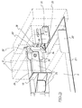
- FIG. 2 An embodiment of a dispensing mechanism in accordance with the invention is shown in Figure 2. Such a mechanism is disposed at one end of each shelf in the vending machine. Three packets 8 are represented by dashed lines in the Figure.
- the block 10 is urged from left to right by a known constant force spring 24.
- the block is slidably mounted against the bracket 16 by means of a "dovetail” type engagement. It is able to move smoothly along the bracket whilst accurately held with its pushing surface perpendicular to the direction of sliding.
- An abutment 28 is disposed at the right hand edge of the shelf 6.
- the packets 8 are urged with a constant pressure against the abutment by the block 10, and are confined in a horizontal stack therebetween.
- the surface provided by the abutment for engaging the end packet of the stack is flat to ensure that the end packet is held in alignment with the rest of the stack, even though it does not contact the lip 21 or the tab 22.
- a microswitch 25 is mounted on this surface, the operation of which is discussed below.
- the longitudinal position of the abutment with respect to the shelf is adjustable by temporarily loosening a screw 27, which passes through a slot 29 in the abutment. Its position may be adjusted, together with that of the tab 22 to ensure only a single packet is dispensed at a time.
- a paddle assembly 30 is rotatably mounted adjacent to the end of the shelf 6. It is driven, under the control of the unit 12, by an electric motor 31 via a reduction gear box 33.
- the paddle configuration shown in Figure 2 has two fingers 32 and 34 (dotted) which pass through the slots 36 in the bracket 26, and above and below the abutment 28, respectively, when the paddle is rotated in the direction of arrow A.
- a product is dispensed from the shelf by rotating the paddle through one complete turn in this direction, and an intermediate position is shown in Figure 3.
- the fingers 32 and 34 After the fingers 32 and 34 pass through the slots 36, they engage the rear surface of the packet at the end of the shelf, and then push it forwards, away from the bracket 26. As the paddle 30 continues to rotate, it pushes the packet past the abutment 28. The horizontal stack can then advance along the shelf, pushing the end pack over the right hand edge of the shelf. It then falls down the vertical channel 14 as discussed above.
- the products likely to be dispensed from this machine are light and supplied in rigid packets. Therefore, the tension in the spring 24 need not be great to retain the packets on the shelf, and as a consequence of these factors, the power required by the paddle is not large.
- the upper surfaces of the shelves are preferably designed to be smooth and to minimise any friction with the products. In addition to minimising the energy consumption of the dispensing mechanism, these considerations also reduce the likelihood of any products being damaged.
- the paddle is shown with two fingers 32 and 34 in Figure 2, other configurations may be adopted as appropriate.
- the fingers are illustrated as being slightly curved and this shape has been found to be advantageous and to dispense the packets in a predictable manner.
- the microswitch 25 provided on the abutment 28 is biased towards the raised position shown in Figure 3.
- the contacts of the microswitch are either open or closed when it is in the raised position, and are in the opposite state when the switch is depressed.
- the microswitch is depressed by the end packet as shown in Figure 2. If a packet is pushed off the end of the shelf 6, the switch briefly moves to the raised position, until the next packet in the stack is pushed thereagainst by the block 10. This brief switching of the microswitch is detected by the control unit 12 to confirm that a packet has been successfully released from the shelf.
- Energisation of the respective motor 31 is stimulated by the control unit for a predetermined period of time after the detection of the switching signal to rotate the paddle 30 to a predetermined position clear of the space above the shelf 6.
- the block 10 is held near the end of the shelf against a stop (not shown) by its spring 24.
- the stop is positioned such that the block is spaced from the microswitch 25 in its raised position. Accordingly, if a microswitch is constantly in the raised position, the control unit 12 can determine that the corresponding shelf is empty. If another shelf holds a stack of the same product, the unit 12 then checks the corresponding microswitch. Otherwise, the unit informs the user the product is not available via the display panel and awaits further input, such as a refund request, further cash or selection of another product. If there is no input after a predetermined time, say fifteen seconds, then the user's cash is automatically refunded.
- a detector 38 (see Figure 1) is provided near the foot of the channel 14, below the lowermost shelf, to sense when a packet passes through the channel.
- the respective motor 31 is activated, and the corresponding paddle rotates dislodging a packet into the channel 14. If the detector senses that a packet has been dispensed, it initiates the stopping of the active motor. It is preferable for the paddle to return to its initial position, as shown in Figure 2, for example. The packets take different times to fall from different shelves to the height of the detector.
- the paddle may therefore be rotated to its original position by operating the motor for a predetermined time following the detection of a packet, taking into account the time taken for the packet to fall from a given shelf. If a packet is not sensed by the detector after a certain period of motor operation, two seconds for example, then this indicates that the particular shelf is empty.
- Figure 4 is a flow chart representing a preferred sequence of operation of a dispensing machine of the invention incorporating the microswitch-based control system.
- the use of an electronic control unit allows such a sequence to be readily altered as appropriate, whilst also requiring minimal power in operation.
Landscapes
- Physics & Mathematics (AREA)
- General Physics & Mathematics (AREA)
- Vending Machines For Individual Products (AREA)
Priority Applications (2)
| Application Number | Priority Date | Filing Date | Title |
|---|---|---|---|
| GB9506697A GB2300184B (en) | 1995-03-31 | 1995-03-31 | Vending machine |
| EP96305835A EP0823697A1 (fr) | 1995-03-31 | 1996-08-08 | Distributeur automatique |
Applications Claiming Priority (2)
| Application Number | Priority Date | Filing Date | Title |
|---|---|---|---|
| GB9506697A GB2300184B (en) | 1995-03-31 | 1995-03-31 | Vending machine |
| EP96305835A EP0823697A1 (fr) | 1995-03-31 | 1996-08-08 | Distributeur automatique |
Publications (1)
| Publication Number | Publication Date |
|---|---|
| EP0823697A1 true EP0823697A1 (fr) | 1998-02-11 |
Family
ID=26143839
Family Applications (1)
| Application Number | Title | Priority Date | Filing Date |
|---|---|---|---|
| EP96305835A Withdrawn EP0823697A1 (fr) | 1995-03-31 | 1996-08-08 | Distributeur automatique |
Country Status (2)
| Country | Link |
|---|---|
| EP (1) | EP0823697A1 (fr) |
| GB (1) | GB2300184B (fr) |
Families Citing this family (2)
| Publication number | Priority date | Publication date | Assignee | Title |
|---|---|---|---|---|
| US7188748B2 (en) | 2003-03-04 | 2007-03-13 | Diaperoos, Llc | Vacuum-packed diaper vending machine |
| US20050131368A2 (en) | 2003-03-04 | 2005-06-16 | Diaperoos, Llc | Vacuum-packed diaper |
Citations (5)
| Publication number | Priority date | Publication date | Assignee | Title |
|---|---|---|---|---|
| US2537300A (en) * | 1947-04-18 | 1951-01-09 | Reliable Metal Engineering Co | Vending machine for packaged articles |
| DE2054373A1 (de) * | 1970-11-05 | 1972-05-10 | Seitz Automaten Gmbh | Warenausgabevorrichtung für Selbstverkäufer mit mehreren horizontalen Warenschächten |
| US3908859A (en) * | 1974-01-31 | 1975-09-30 | S J Agnew Agnew Environmental | Article dispensing apparatus |
| WO1988004086A1 (fr) * | 1986-11-24 | 1988-06-02 | Bergsten Curt Arne | Cassette a articles pour distributeur automatique |
| DE3824214A1 (de) * | 1988-07-16 | 1990-01-18 | Haendler Metall & Masch | Warenautomat |
Family Cites Families (1)
| Publication number | Priority date | Publication date | Assignee | Title |
|---|---|---|---|---|
| DE1449207A1 (de) * | 1964-11-12 | 1969-01-16 | Financ Luxembourgeoise S A | Selbstverkaeufer fuer Druckschriften |
-
1995
- 1995-03-31 GB GB9506697A patent/GB2300184B/en not_active Expired - Fee Related
-
1996
- 1996-08-08 EP EP96305835A patent/EP0823697A1/fr not_active Withdrawn
Patent Citations (5)
| Publication number | Priority date | Publication date | Assignee | Title |
|---|---|---|---|---|
| US2537300A (en) * | 1947-04-18 | 1951-01-09 | Reliable Metal Engineering Co | Vending machine for packaged articles |
| DE2054373A1 (de) * | 1970-11-05 | 1972-05-10 | Seitz Automaten Gmbh | Warenausgabevorrichtung für Selbstverkäufer mit mehreren horizontalen Warenschächten |
| US3908859A (en) * | 1974-01-31 | 1975-09-30 | S J Agnew Agnew Environmental | Article dispensing apparatus |
| WO1988004086A1 (fr) * | 1986-11-24 | 1988-06-02 | Bergsten Curt Arne | Cassette a articles pour distributeur automatique |
| DE3824214A1 (de) * | 1988-07-16 | 1990-01-18 | Haendler Metall & Masch | Warenautomat |
Also Published As
| Publication number | Publication date |
|---|---|
| GB2300184A (en) | 1996-10-30 |
| GB9506697D0 (en) | 1995-05-24 |
| GB2300184B (en) | 1998-09-09 |
Similar Documents
| Publication | Publication Date | Title |
|---|---|---|
| EP0958558B1 (fr) | Distributeur automatique de journaux et periodiques | |
| US11141328B1 (en) | High capacity hygiene product dispenser | |
| US5605249A (en) | Battery operated vending machine having a carousel stacking arrangement and plunger-type dispenser | |
| US5251738A (en) | Currency handling system | |
| US5167345A (en) | Dual dispenser | |
| US5941414A (en) | Apparatus for dispensing tickets, cards and the like from a stack | |
| US4940162A (en) | Rolled coin dispenser | |
| US4043483A (en) | Drawer apparatus for article dispensing machine | |
| US7244175B2 (en) | Coin recycling machine and method | |
| EP0256882A2 (fr) | Conteneur d'une machine de vente | |
| WO1997008666A1 (fr) | Dispositif de stockage dans un distributeur | |
| EP0319492B1 (fr) | Distributeur automatique de marchandises cylindriques, en particulier de rouleaux de pièces de monnaie | |
| EP0178244B1 (fr) | Dispositif vendeur d'articles | |
| US6938896B2 (en) | Automatic card dispensing unit with display capability | |
| EP1008116B1 (fr) | Appareil de distribution de pieces | |
| GB2300184A (en) | Dispensing mechanism | |
| US6926167B2 (en) | Carton dispensing machine | |
| US4389000A (en) | Newspaper vending machine | |
| US20040069591A1 (en) | Token dispensing and banknote changing device | |
| US6382387B1 (en) | Vending machine having a mechanism for preventing a knob from turning and accepting money when the machine is out of product | |
| EP0905659A1 (fr) | Distributeur de cartes | |
| KR102525991B1 (ko) | 멀티자동판매기의 상품 배출장치 | |
| US5277330A (en) | Automatic distributor for packaged articles | |
| US6196415B1 (en) | Single copy newspaper dispenser | |
| US2821329A (en) | Vending machine |
Legal Events
| Date | Code | Title | Description |
|---|---|---|---|
| PUAI | Public reference made under article 153(3) epc to a published international application that has entered the european phase |
Free format text: ORIGINAL CODE: 0009012 |
|
| AK | Designated contracting states |
Kind code of ref document: A1 Designated state(s): AT BE CH DE DK ES FI FR GB GR IE IT LI NL PT SE |
|
| 17P | Request for examination filed |
Effective date: 19980624 |
|
| AKX | Designation fees paid |
Free format text: AT BE CH DE DK ES FI FR GB GR IE IT LI NL PT SE |
|
| RBV | Designated contracting states (corrected) |
Designated state(s): AT BE CH DE DK ES FI FR GB GR IE IT LI NL PT SE |
|
| 17Q | First examination report despatched |
Effective date: 20000621 |
|
| GRAH | Despatch of communication of intention to grant a patent |
Free format text: ORIGINAL CODE: EPIDOS IGRA |
|
| STAA | Information on the status of an ep patent application or granted ep patent |
Free format text: STATUS: THE APPLICATION IS DEEMED TO BE WITHDRAWN |
|
| 18D | Application deemed to be withdrawn |
Effective date: 20030829 |