EP0823698B1 - Améliorations relatives à des systèmes d'affichage à miroir numériques - Google Patents
Améliorations relatives à des systèmes d'affichage à miroir numériques Download PDFInfo
- Publication number
- EP0823698B1 EP0823698B1 EP96112890A EP96112890A EP0823698B1 EP 0823698 B1 EP0823698 B1 EP 0823698B1 EP 96112890 A EP96112890 A EP 96112890A EP 96112890 A EP96112890 A EP 96112890A EP 0823698 B1 EP0823698 B1 EP 0823698B1
- Authority
- EP
- European Patent Office
- Prior art keywords
- color
- digital micromirror
- micromirror device
- signal
- boundary
- Prior art date
- Legal status (The legal status is an assumption and is not a legal conclusion. Google has not performed a legal analysis and makes no representation as to the accuracy of the status listed.)
- Expired - Lifetime
Links
- 238000000034 method Methods 0.000 claims description 19
- 230000007704 transition Effects 0.000 claims description 18
- 239000003086 colorant Substances 0.000 claims description 8
- 230000004044 response Effects 0.000 claims description 4
- 230000003190 augmentative effect Effects 0.000 claims 2
- 230000008878 coupling Effects 0.000 claims 1
- 238000010168 coupling process Methods 0.000 claims 1
- 238000005859 coupling reaction Methods 0.000 claims 1
- 238000010586 diagram Methods 0.000 description 4
- 230000005540 biological transmission Effects 0.000 description 2
- 230000000694 effects Effects 0.000 description 2
- 230000006870 function Effects 0.000 description 2
- 230000010354 integration Effects 0.000 description 2
- 230000003068 static effect Effects 0.000 description 2
- 238000005286 illumination Methods 0.000 description 1
- 239000004065 semiconductor Substances 0.000 description 1
- 238000001228 spectrum Methods 0.000 description 1
Images



Classifications
-
- G—PHYSICS
- G09—EDUCATION; CRYPTOGRAPHY; DISPLAY; ADVERTISING; SEALS
- G09G—ARRANGEMENTS OR CIRCUITS FOR CONTROL OF INDICATING DEVICES USING STATIC MEANS TO PRESENT VARIABLE INFORMATION
- G09G3/00—Control arrangements or circuits, of interest only in connection with visual indicators other than cathode-ray tubes
- G09G3/20—Control arrangements or circuits, of interest only in connection with visual indicators other than cathode-ray tubes for presentation of an assembly of a number of characters, e.g. a page, by composing the assembly by combination of individual elements arranged in a matrix no fixed position being assigned to or needed to be assigned to the individual characters or partial characters
- G09G3/34—Control arrangements or circuits, of interest only in connection with visual indicators other than cathode-ray tubes for presentation of an assembly of a number of characters, e.g. a page, by composing the assembly by combination of individual elements arranged in a matrix no fixed position being assigned to or needed to be assigned to the individual characters or partial characters by control of light from an independent source
- G09G3/3433—Control arrangements or circuits, of interest only in connection with visual indicators other than cathode-ray tubes for presentation of an assembly of a number of characters, e.g. a page, by composing the assembly by combination of individual elements arranged in a matrix no fixed position being assigned to or needed to be assigned to the individual characters or partial characters by control of light from an independent source using light modulating elements actuated by an electric field and being other than liquid crystal devices and electrochromic devices
- G09G3/346—Control arrangements or circuits, of interest only in connection with visual indicators other than cathode-ray tubes for presentation of an assembly of a number of characters, e.g. a page, by composing the assembly by combination of individual elements arranged in a matrix no fixed position being assigned to or needed to be assigned to the individual characters or partial characters by control of light from an independent source using light modulating elements actuated by an electric field and being other than liquid crystal devices and electrochromic devices based on modulation of the reflection angle, e.g. micromirrors
-
- G—PHYSICS
- G02—OPTICS
- G02B—OPTICAL ELEMENTS, SYSTEMS OR APPARATUS
- G02B26/00—Optical devices or arrangements for the control of light using movable or deformable optical elements
- G02B26/007—Optical devices or arrangements for the control of light using movable or deformable optical elements the movable or deformable optical element controlling the colour, i.e. a spectral characteristic, of the light
- G02B26/008—Optical devices or arrangements for the control of light using movable or deformable optical elements the movable or deformable optical element controlling the colour, i.e. a spectral characteristic, of the light in the form of devices for effecting sequential colour changes, e.g. colour wheels
-
- G—PHYSICS
- G02—OPTICS
- G02B—OPTICAL ELEMENTS, SYSTEMS OR APPARATUS
- G02B26/00—Optical devices or arrangements for the control of light using movable or deformable optical elements
- G02B26/08—Optical devices or arrangements for the control of light using movable or deformable optical elements for controlling the direction of light
- G02B26/0816—Optical devices or arrangements for the control of light using movable or deformable optical elements for controlling the direction of light by means of one or more reflecting elements
- G02B26/0833—Optical devices or arrangements for the control of light using movable or deformable optical elements for controlling the direction of light by means of one or more reflecting elements the reflecting element being a micromechanical device, e.g. a MEMS mirror, DMD
- G02B26/0841—Optical devices or arrangements for the control of light using movable or deformable optical elements for controlling the direction of light by means of one or more reflecting elements the reflecting element being a micromechanical device, e.g. a MEMS mirror, DMD the reflecting element being moved or deformed by electrostatic means
-
- H—ELECTRICITY
- H04—ELECTRIC COMMUNICATION TECHNIQUE
- H04N—PICTORIAL COMMUNICATION, e.g. TELEVISION
- H04N9/00—Details of colour television systems
- H04N9/12—Picture reproducers
- H04N9/31—Projection devices for colour picture display, e.g. using electronic spatial light modulators [ESLM]
- H04N9/3102—Projection devices for colour picture display, e.g. using electronic spatial light modulators [ESLM] using two-dimensional electronic spatial light modulators
- H04N9/3111—Projection devices for colour picture display, e.g. using electronic spatial light modulators [ESLM] using two-dimensional electronic spatial light modulators for displaying the colours sequentially, e.g. by using sequentially activated light sources
- H04N9/3114—Projection devices for colour picture display, e.g. using electronic spatial light modulators [ESLM] using two-dimensional electronic spatial light modulators for displaying the colours sequentially, e.g. by using sequentially activated light sources by using a sequential colour filter producing one colour at a time
-
- G—PHYSICS
- G09—EDUCATION; CRYPTOGRAPHY; DISPLAY; ADVERTISING; SEALS
- G09G—ARRANGEMENTS OR CIRCUITS FOR CONTROL OF INDICATING DEVICES USING STATIC MEANS TO PRESENT VARIABLE INFORMATION
- G09G2310/00—Command of the display device
- G09G2310/02—Addressing, scanning or driving the display screen or processing steps related thereto
- G09G2310/0235—Field-sequential colour display
-
- G—PHYSICS
- G09—EDUCATION; CRYPTOGRAPHY; DISPLAY; ADVERTISING; SEALS
- G09G—ARRANGEMENTS OR CIRCUITS FOR CONTROL OF INDICATING DEVICES USING STATIC MEANS TO PRESENT VARIABLE INFORMATION
- G09G2320/00—Control of display operating conditions
- G09G2320/02—Improving the quality of display appearance
- G09G2320/0271—Adjustment of the gradation levels within the range of the gradation scale, e.g. by redistribution or clipping
- G09G2320/0276—Adjustment of the gradation levels within the range of the gradation scale, e.g. by redistribution or clipping for the purpose of adaptation to the characteristics of a display device, i.e. gamma correction
Definitions
- This invention relates to Digital Micromirror Display (DMD) systems and more particularly to accentuating intense white display areas in sequential DMD video systems.
- DMD Digital Micromirror Display
- a CRT (cathode ray tube) video display has the capacity to overdrive its output intensity over small scene areas that are very bright with respect to the rest of the scene. This trait produces an effect that emphasizes locally bright areas with an intensity higher than that achievable over the entire scene. This effect is desirable in many circumstances.
- the digital micromirror device comprises a spatial light modulator.
- the DMD, or digital micromirror, device covers each memory cell of a CMOS STATIC RAM with a movable micromirror. Electrostatic forces based on the data in this cell tilt the mirror plus and minus a few degrees, modulating the light incident on the surface. In one example, the tilt is 10°.
- the light reflected from any of the mirrors passes through a projection lens and creates an image on a large screen.
- a sequential color DMD display that employs a color wheel uses pulse width modulation (PWM) to depict the intensities for each pixel in each wheel color. Individual mirrors are switched between the "OFF” and “ON” state so that each is turned “ON” for a portion of the time where the DMD is uniformly illuminated with a single color.
- PWM pulse width modulation
- the "ON" time for a mirror is proportional to desired intensity in that color. Since all available time in one color is used to depict the full scale intensity, a DMD display cannot "overdrive” pixels in particular colors without reducing the amount of time useable for proportional pulse width modulation.
- the invention concerns a device according to claim 14 and a method according to claim 1.
- a method and system for accentuating intense light display areas in sequential DMD video systems is provided by generating a special bit for each pixel that indicates whether to boost the intensity of that pixel in all colors. These bits are loaded into the DMD array at the start of all color transition periods to cause individual pixels to be turned "ON" during these times.
- FIG. 1 there is illustrated an overall system diagram of a digital micromirror device (DMD) display system 10 wherein the light from a source 11 is applied through a first condenser lens 13 and through a color wheel 15, which is rotating about 60 cycles, or Hertz, or 60 frames per second.
- the light passing through the color wheel passes through a second condenser lens onto a DMD chip 19.
- the DMD chip includes an array of tiny mirrored elements, or micromirrors, where each mirror element is hinged by a torsion hinge and support posts above a memory cell of a CMOS STATIC RAM, as shown in Fig. 2.
- the movable micromirror tilts into an "ON" or “OFF” state by electrostatic forces based on data in the cell.
- the tilt of the mirror is either plus or minus, for example 10° (OFF) to modulate the light that is incident on the surface.
- the light reflected from any of the mirrors may pass through a projection lens 20 and create images on a large screen 21.
- the portion of time during which that the mirror remains in the "ON" state determines the shade of gray.
- the time duration which the cell is in the positive direction, or "ON" is represented by 8 bits of data sent to that cell.
- the color wheel 15 is divided into for example red, green, and blue sectors. In the color wheel example for red, green, and blue the maximum red would be when the red would be reflecting the maximum period of time.
- the micromirror would be in the "ON" position when the light was passing through essentially the entire time the wheel is in the red sector. The same would be true for the other two colors. The minimum would be where the micromirror would be in the "OFF” state through the entire period when the color wheel was in the color position.
- the intensity resolution in this pulse width modulation (PWM) is limited by the response time of the digital DMD mirrors.
- the total time available to display a color frame and the least time required to turn a mirror to the "ON" state and back to the "OFF” state define the resolution of the present systems. In the arrangement for the 8-bits, the most significant bit is illustrated in Fig.
- 3 is the seventh bit with that bit representing the longest "ON” time, the sixth bit then representing the next longest “ON” time, and the fifth bit representing the third longest “ON” time, etc.
- the least significant, or 0 bit would represent the shortest period of time. For a sequential color DMD system five milliseconds is available for a color frame. For 8-bit binary PWM, the last significant bit (0 bit on only), the shortest period would be on for about 19.6 microseconds. The mirror "OFF/ON" time would have to be less and 19.6 microseconds to implement this scheme with the current method.
- the solution to provide a method for accentuating intense white display areas is to generate a special bit for each pixel that indicates whether to boost the intensity of that pixel in all colors. These bits are then loaded into a DMD array at the start of all color transition periods so that instead of always setting the mirror to the "OFF" state during color transmission periods, the individual pixels can be turned “ON” during these times.
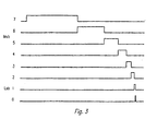
- FIG. 4 there is illustrated the color wheel transition on a split reset DMD.
- a transition from a color A to a color B In the time period in the middle, represented between the center dashed lines, there is illustrated a time period of the color wheel transition between a color A and a color B in which the system is normally "OFF".
- the vertical axis there is represented 16 reset groups 0 - 15.
- the phase "OFF" to phase "ON” is represented by the stepped groups 0 - 15 with the group 0 being turned “OFF” at time X and turned “ON” at time Y.
- the groups 1 - 15 are sequentially phased off from time X + 1 through time X + 15 with X + 15 being the time in which the reset group 15 is turned “OFF.”
- the time period in which group 0 is turned “ON” is again time Y and the reset groups from 1 to 15 are sequentially turned on from time Y + 1 up to time Y + 15.
- the period of the phase "OFF" to phase "ON” is represented by the figure depending on the group.
- the period from X to Y for reset group 0 would represent the total period.
- For group 15 from X + 15 to Y + 15 would represent the light boost period for the group 15.
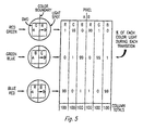
- Fig. 5 there is illustrated the percentage of each color light during each transmission of a light spot for pixels at points A and B.
- the red sector at point A is on for 1 percent of the time and the green is on for 99 percent of the time.
- the red would exist for 99 percent of the time with there being 1 percent for the green and none to blue.
- pixel B For the picture element at point B, pixel B would receive 99 percent of the color in green and 1 percent in blue. For the transition between blue and with the pixel elements located at points A and B, the pixel element at point A would receive 99 percent in red and 1 percent blue with no percentage for green. For the pixel at point B for a blue to a red transition, there would be 1 percent red, 0 percent green and 99 percent blue. Over the full cycle of the color wheel each color red, green, and blue for both pixel locations would equally receive 100 percent of the light by integration provide white light.
- a simple method is used to detect the regions of the image which must be "peaked” as described as follows.
- the system detects peaks by comparing red, green, and blue digital signals and sets a boost bit for pixels with equal values of red, green, and blue that over a predetermined threshold.
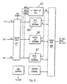
- the red, green and blue outputs from the color converter 61 are applied to a white bit generator 63 and separately to red, green and blue degamma Lookup tables (LUT) 65, 66, and 67, respectively.
- LUT Lookup tables
- 8 bits describes the intensity levels for the red, green and blue signals.
- each pixel value is divided by 32.
- the intensity levels can be represented by other number of bits such as 6.
- a frame RAM (Random Access Memory) 69 stores a complete frame of pixels where 25 bits are stored in this embodiment for each pixel. There are 8 bits for each color or 24 bits and 1 bit from generator 63.
- a white bit (logic one level for example)is provided. In one preferred embodiment this may be when all three levels are also equal.
- the threshold is so when the three colors are combined one gets for that pixel a white color of sufficient intensity to be at boost white level. This comparing may be done by comparing the three MSB (most significant bits) or equivalent.
- the white bit is also applied to the DMD control and DMDRAM control.
- the DMDRAM control tells the frame RAM where to get the data, which of the 25 bits, etc.
- the DMD control is sent to the DMD directly.
- the white bit is loaded into the DMD array at the start of all color transitions to cause the individual pixels to be turned on during these times.
- the white bit may also be applied to each of the three LUTs 65,66,and 67 (Filter 64 in Fig.1).
- the degamma LUTs are discussed in Publication European Patent document No.0,704,835.
- the generated white bit is applied to the LUTs 65, 66, and 67 the tables call up a higher transfer function so a higher intensity level is provided out of each LUT to provide a smooth ramping function for the higher light level.
Landscapes
- Physics & Mathematics (AREA)
- General Physics & Mathematics (AREA)
- Engineering & Computer Science (AREA)
- Optics & Photonics (AREA)
- Astronomy & Astrophysics (AREA)
- Spectroscopy & Molecular Physics (AREA)
- Computer Hardware Design (AREA)
- Theoretical Computer Science (AREA)
- Multimedia (AREA)
- Signal Processing (AREA)
- Mechanical Light Control Or Optical Switches (AREA)
- Projection Apparatus (AREA)
Claims (22)
- Procédé pour accentuer des zones d'affichage d'un blanc intense dans un système vidéo d'un dispositif séquentiel à micro-miroirs numérique, comportant une roue des couleurs possédant au moins deux secteurs ayant des couleurs différentes et une source de lumière éclairant la roue des couleurs, le procédé comprenant l'étape consistant à:produire un signal qui est indicatif de l'intensité de blanc d'intensification; etamener un dispositif à micro-miroirs numérique, pendant la présence dudit signal, à être située dans une position "ACTIVÉE" pendant une période pendant laquelle la lumière de la source de lumière pour le dispositif à micro-miroirs numérique franchit une limite entre couleurs entre deux secteurs voisins ayant des couleurs différentes de la roue des couleurs.
- Procédé selon la revendication 1, selon lequel ladite étape de production dudit signal comprend la production d'un signal pour chaque pixel d'un réseau de pixels, ledit signal étant indicatif d'une intensité de blanc d'intensification du au moins un pixel dans toutes les couleurs.
- Procédé selon la revendication 1 ou la revendication 2, dans lequel ladite étape d'activation consiste à amener ledit dispositif à micro-miroirs numérique à être dans une position "ACTIVÉE" pendant des périodes pendant lesquelles une source de lumière franchit une limite entre couleurs de ladite roue des couleurs de sorte que ledit dispositif à micro-miroirs numérique reçoit des mélanges différents de lumières de couleurs, qui sont intégrés entre eux pour produire un blanc intense.
- Procédé selon l'une quelconque des revendications précédentes comprenant, après ladite étape de production, l'étape de chargement desdits signaux dans un réseau d'un dispositif à micro-miroirs numérique au début de toutes les périodes de transition entre les couleurs.
- Procédé selon l'une quelconque des revendications précédentes, selon lequel ladite étape de production comprend la comparaison de signaux rouge, vert et bleu et la production d'un signal d'intensification lorsque le dispositif à micro-miroirs numérique pour le rouge, le vert et le bleu dépasse un seuil donné.
- Procédé selon la revendication 5, comprenant en outre l'étape consistant à augmenter une fonction de transfert initiale dans des tables de consultation degamma pour les couleurs rouge, verte et bleue en réponse au signal produit.
- Procédé selon la revendication 6, comprenant en outre l'utilisation dudit signal pour modifier le gain dans les tables de consultation degamma pour produire une fonction de montée en rampe uniforme.
- Procédé selon l'une quelconque des revendications précédentes comprenant en outre la mise à l'état "DESACTIVÉ" de l'ensemble desdits dispositifs à micro-miroirs numérique dans une période limite absolue, et la mise à l'état "DESACTIVÉ" de l'ensemble dudit dispositif à micro-miroirs numérique dans une première période de transition avant ladite période de limite absolue.
- Procédé selon la revendication 8, selon lequel ladite étape de mise à l'état "DESACTIVÉ" desdits dispositifs à micro-miroirs numérique comprend séquentiellement la mise à l'état "DESACTIVÉ" desdits dispositifs à micro-miroirs numérique selon des groupes avant ladite limite absolue et, dans une seconde période de transition succédant à ladite limite de couleur absolue, lesdits groupes échelonnés de dispositifs à micro-miroirs numérique sont placés à l'état "ACTIVÉ" dans le même ordre.
- Procédé selon la revendication 9, selon lequel ladite étape de production dudit signal comprend la production dudit signal lorsque l'ensemble desdits signaux vidéo couleurs possèdent essentiellement la même intensité supérieure à un seuil donné.
- Procédé selon l'une quelconque des revendications précédentes, comprenant en outré l'éclairement des dispositifs à micro-miroirs numériques avec une source de lumière à travers une roue des couleurs, des limites de la roue des couleurs étant formées selon des groupes de dispositifs à micro-miroirs numériques, qui sont séquentiellement placés à l'état "DÉSACTIVÉ", et lesdits groupes échelonnés étant séquentiellement placés l'état "ACTIVÉ" dans le même ordre.
- Procédé selon les revendications 8 à 11, comprenant en outre le fait de prévoir une source d'au moins trois signaux vidéo couleurs.
- Procédé selon les revendications 8 à 12 comprenant en outre le fait de prévoir des tables de consultation degamma pour chaque couleur et de coupler ledit signal auxdites tables et d'augmenter ainsi le gain à partir desdites tables en réponse audit signal.
- Système pour accentuer des zones d'affichage de blanc intense dans un système vidéo séquentiel de dispositifs à micro-miroirs numériques avec une roue des couleurs possédant au moins deux secteurs ayant des couleurs différentes et une source de lumière éclairant la roue des couleurs, le système comprenant :un générateur couplé à des signaux vidéo couleurs arrivants pour produire un signal représentant l'intensité lumineuse des signaux vidéo au-dessus d'un seuil donné;une unité de commande couplée au dispositif à micro-miroirs numérique et agencée de manière à amener un micro-miroir numérique dans l'état "ACTIVÉ" pendant une période pendant laquelle une lumière provenant de la source de lumière franchit une limite des couleurs entre deux secteurs voisins ayant des couleurs différentes de la roue des couleurs lorsque ledit signal représente l'intensité lumineuse du signal vidéo au-dessus d'un seuil donné.
- Système selon la revendication 14, dans lequel les signaux vidéo en couleurs sont les signaux vidéo rouge, vert et bleu.
- Système selon l'une quelconque des revendications 14 et 15, comprenant en outre des tables de consultation degamma couplées à chaque signal vidéo arrivant pour produire une première fonction de transfert, lesdites tables de consultation degamma augmentant ladite fonction de transfert en réponse audit signal.
- Système selon l'une quelconque des revendications 14 à 16, dans laquelle au niveau des limites des couleurs, des groupes étagés de dispositifs à micro-miroirs numériques sont placés séquentiellement à l'état DÉSACTIVÉ, et lesdits groupes étagés de dispositifs à micro-miroirs numériques sont placés séquentiellement à l'état ACTIVÉ dans le même ordre.
- Système selon l'une quelconque des revendications 14 à 17 comprenant en outre une source d'au moins trois signaux vidéo en couleurs, et dans lequel ladite unité de commande amène lesdits dispositifs à micro-miroirs numériques à rester à l'état "ACTIVÉ" au niveau desdites limites des couleurs.
- Système selon l'une quelconque des revendications 14 à 18, comprenant en outre des tables de consultation degamma avec une table degamma pour chaque couleur, lesdites tables de consultation étant couplées audit générateur et étant sensibles à la production dudit signal pour intensifier une fonction de transfert desdites tables.
- Système selon l'une quelconque des revendications 14 à 19, dans lequel dans une période de limite absolue de la roue des couleurs, l'ensemble desdits dispositifs à micro-miroirs numériques sont placés à l'état "DÉSACTIVÉ" et, dans une première période de transition avant ladite période limite absolue de la ou des couleurs, lesdits dispositifs à micro-miroirs numériques sont placés séquentiellement à l'état "DÉSACTIVÉ" selon des groupes avant ladite limite de couleur absolue, et dans une seconde période de transition qui succède à la limite de couleur absolue, lesdits groupes échelonnés de dispositifs à micro-miroirs numériques sont placés séquentiellement à l'état "ACTIVÉ" dans le même ordre.
- Système selon la revendication 20, dans lequel ladite unité de commande permet la mise des dispositifs à micro-miroirs numériques à l'état "ACTIVÉ" pendant lesdites limites de couleurs absolues et lesdites première et seconde périodes de transition.
- Système selon l'une quelconque des revendications 14 à 21, dans lequel ledit système est un système vidéo à dispositif à miroirs numériques à remise à l'état initial séparée.
Priority Applications (3)
| Application Number | Priority Date | Filing Date | Title |
|---|---|---|---|
| US08/368,448 US5592188A (en) | 1995-01-04 | 1995-01-04 | Method and system for accentuating intense white display areas in sequential DMD video systems |
| EP96112890A EP0823698B1 (fr) | 1995-01-04 | 1996-08-09 | Améliorations relatives à des systèmes d'affichage à miroir numériques |
| DE69627845T DE69627845T2 (de) | 1996-08-09 | 1996-08-09 | Verbesserungen an Anzeigesystemen mit digitaler Spiegelvorrichtung |
Applications Claiming Priority (2)
| Application Number | Priority Date | Filing Date | Title |
|---|---|---|---|
| US08/368,448 US5592188A (en) | 1995-01-04 | 1995-01-04 | Method and system for accentuating intense white display areas in sequential DMD video systems |
| EP96112890A EP0823698B1 (fr) | 1995-01-04 | 1996-08-09 | Améliorations relatives à des systèmes d'affichage à miroir numériques |
Publications (2)
| Publication Number | Publication Date |
|---|---|
| EP0823698A1 EP0823698A1 (fr) | 1998-02-11 |
| EP0823698B1 true EP0823698B1 (fr) | 2003-05-02 |
Family
ID=26142127
Family Applications (1)
| Application Number | Title | Priority Date | Filing Date |
|---|---|---|---|
| EP96112890A Expired - Lifetime EP0823698B1 (fr) | 1995-01-04 | 1996-08-09 | Améliorations relatives à des systèmes d'affichage à miroir numériques |
Country Status (2)
| Country | Link |
|---|---|
| US (1) | US5592188A (fr) |
| EP (1) | EP0823698B1 (fr) |
Families Citing this family (92)
| Publication number | Priority date | Publication date | Assignee | Title |
|---|---|---|---|---|
| US6535187B1 (en) * | 1998-04-21 | 2003-03-18 | Lawson A. Wood | Method for using a spatial light modulator |
| US5832151A (en) * | 1995-01-17 | 1998-11-03 | Remote Source Lighting International, Inc | Reflector and illumination system |
| US7253794B2 (en) * | 1995-01-31 | 2007-08-07 | Acacia Patent Acquisition Corporation | Display apparatus and method |
| US6969635B2 (en) * | 2000-12-07 | 2005-11-29 | Reflectivity, Inc. | Methods for depositing, releasing and packaging micro-electromechanical devices on wafer substrates |
| DE29614692U1 (de) * | 1996-04-30 | 1996-10-24 | Balzers Prozess Systeme Vertriebs- und Service GmbH, 81245 München | Farbrad und Bilderzeugungsvorrichtung mit einem Farbrad |
| DE19622314A1 (de) * | 1996-06-04 | 1997-12-11 | Sel Alcatel Ag | Telekommunikationsendgerät und Vorrichtung zur Projektion von visuell erfaßbarer Information |
| DE19712844A1 (de) * | 1997-03-26 | 1998-10-08 | Siemens Ag | Verfahren zur dreidimensionalen Identifizierung von Objekten |
| WO1999056166A2 (fr) * | 1998-04-28 | 1999-11-04 | Carl Zeiss Jena Gmbh | Dispositif de projection |
| US6024453A (en) * | 1997-04-29 | 2000-02-15 | Balzers Aktiengesellshaft | Method of rapidly producing color changes in an optical light path |
| US6392717B1 (en) | 1997-05-30 | 2002-05-21 | Texas Instruments Incorporated | High brightness digital display system |
| US6256425B1 (en) * | 1997-05-30 | 2001-07-03 | Texas Instruments Incorporated | Adaptive white light enhancement for displays |
| US5815303A (en) * | 1997-06-26 | 1998-09-29 | Xerox Corporation | Fault tolerant projective display having redundant light modulators |
| US5790297A (en) | 1997-06-26 | 1998-08-04 | Xerox Corporation | Optical row displacement for a fault tolerant projective display |
| US5774254A (en) * | 1997-06-26 | 1998-06-30 | Xerox Corporation | Fault tolerant light modulator display system |
| US5924013A (en) * | 1997-09-03 | 1999-07-13 | Guido; Mary M. | Method and apparatus for transmitting motion picture cinematic information for viewing in movie theaters and ordering method therefor |
| WO1999064784A1 (fr) * | 1998-06-08 | 1999-12-16 | Karlheinz Strobl | Systemes d'eclairage efficaces, leurs composants, et leurs procedes de fabrication |
| JP2000013814A (ja) * | 1998-06-19 | 2000-01-14 | Pioneer Electron Corp | 映像信号処理回路 |
| US6962419B2 (en) | 1998-09-24 | 2005-11-08 | Reflectivity, Inc | Micromirror elements, package for the micromirror elements, and projection system therefor |
| US6573951B1 (en) | 1998-10-09 | 2003-06-03 | Texas Instruments Incorporated | Non-terminating pulse width modulation for displays |
| JP4122594B2 (ja) | 1998-10-21 | 2008-07-23 | 三菱電機株式会社 | 光学装置、並びに、それを用いたプロジェクタ装置、リアプロジェクタ装置及びマルチプロジェクタ装置 |
| JP3132505B2 (ja) * | 1999-01-14 | 2001-02-05 | セイコーエプソン株式会社 | 投写型表示装置 |
| US6415023B2 (en) | 1999-01-22 | 2002-07-02 | Pointset Corporation | Method and apparatus for setting programmable features of an appliance |
| US6256378B1 (en) * | 1999-01-22 | 2001-07-03 | Pointset Corporation | Method and apparatus for setting programmable features of an appliance |
| US7289611B2 (en) * | 1999-01-22 | 2007-10-30 | Pointset Corporation | Method and apparatus for setting programmable features of motor vehicle |
| US7415102B2 (en) | 1999-01-22 | 2008-08-19 | Pointset Corporation | Method and apparatus for setting programmable features of an appliance |
| US6882712B1 (en) | 1999-01-22 | 2005-04-19 | Pointset Corporation | Method and apparatus for setting programmable features of an appliance |
| US6483906B1 (en) | 1999-01-22 | 2002-11-19 | Pointset Corporation | Method and apparatus for setting programmable features of an appliance |
| US6281820B1 (en) * | 1999-07-12 | 2001-08-28 | Pointset Corporation | Methods and apparatus for transferring data from a display screen |
| JP2001100699A (ja) | 1999-09-29 | 2001-04-13 | Canon Inc | 投射型表示装置とその応用システム |
| US6771325B1 (en) | 1999-11-05 | 2004-08-03 | Texas Instruments Incorporated | Color recapture for display systems |
| US7118226B2 (en) * | 1999-11-05 | 2006-10-10 | Texas Instruments Incorporated | Sequential color recapture for image display systems |
| JP4574057B2 (ja) * | 2000-05-08 | 2010-11-04 | キヤノン株式会社 | 表示装置 |
| JP2002082652A (ja) * | 2000-05-18 | 2002-03-22 | Canon Inc | 画像表示装置および方法 |
| US6870523B1 (en) * | 2000-06-07 | 2005-03-22 | Genoa Color Technologies | Device, system and method for electronic true color display |
| US7167297B2 (en) * | 2000-08-30 | 2007-01-23 | Reflectivity, Inc | Micromirror array |
| US7230656B2 (en) * | 2000-11-30 | 2007-06-12 | Texas Instruments Incorporated | Sequential color filter |
| US7352488B2 (en) * | 2000-12-18 | 2008-04-01 | Genoa Color Technologies Ltd | Spectrally matched print proofer |
| AU2002216348A1 (en) * | 2000-12-18 | 2002-07-01 | Genoa Color Technologies Ltd. | Spectrally matched print proofer |
| EP1227687A3 (fr) * | 2000-12-30 | 2005-05-25 | Texas Instruments Incorporated | Système pour la réduction de défauts de séparation de couleur dans un appareil d'affichage séquentiel d'images |
| US6726333B2 (en) | 2001-02-09 | 2004-04-27 | Reflectivity, Inc | Projection display with multiply filtered light |
| JP4628566B2 (ja) * | 2001-03-12 | 2011-02-09 | 三菱電機株式会社 | 画像投写装置 |
| US6719429B2 (en) * | 2001-03-30 | 2004-04-13 | Infocus Corporation | Anamorphic illumination of micro-electromechanical display devices employed in multimedia projectors |
| EP2239725B1 (fr) | 2001-06-07 | 2013-10-23 | Genoa Color Technologies Ltd. | Systeme et procede de conversion de donnees destines a des afficheurs a large gamme de couleurs |
| US7714824B2 (en) * | 2001-06-11 | 2010-05-11 | Genoa Color Technologies Ltd. | Multi-primary display with spectrally adapted back-illumination |
| EP1419497A4 (fr) * | 2001-06-11 | 2005-11-16 | Genoa Color Technologies Ltd | Dispositif, systeme et procede d'affichage en couleur |
| US8289266B2 (en) | 2001-06-11 | 2012-10-16 | Genoa Color Technologies Ltd. | Method, device and system for multi-color sequential LCD panel |
| IL159779A0 (en) * | 2001-07-12 | 2004-06-20 | Genoa Technologies Ltd | Sequential projection color display using multiple imaging panels |
| WO2003010745A1 (fr) * | 2001-07-23 | 2003-02-06 | Genoa Technologies Ltd. | Affichage pour simulation de materiau imprime |
| US7023606B2 (en) * | 2001-08-03 | 2006-04-04 | Reflectivity, Inc | Micromirror array for projection TV |
| KR20030018740A (ko) * | 2001-08-31 | 2003-03-06 | 삼성전자주식회사 | 투사 장치 |
| EP1461665A4 (fr) * | 2002-01-07 | 2006-11-02 | Genoa Color Technologies Ltd | Afficheur couleur electronique utilise pour la production d'une epreuve-ecran |
| US20040155856A1 (en) * | 2002-01-16 | 2004-08-12 | Peter Richards | Sequential color illumination in display systems employing light modulators |
| CN101840687B (zh) * | 2002-04-11 | 2013-09-18 | 格诺色彩技术有限公司 | 具有增强的属性的彩色显示装置和方法 |
| US7061512B2 (en) * | 2002-06-11 | 2006-06-13 | Texas Instruments Incorporated | Constant-weight bit-slice PWM method and system for scrolling color display systems |
| CN1717715A (zh) * | 2002-07-24 | 2006-01-04 | 吉诺彩色技术有限公司 | 高亮度宽色域显示 |
| CN1742304A (zh) | 2003-01-28 | 2006-03-01 | 皇家飞利浦电子股份有限公司 | 用于具有多于三种原色的显示器的最佳子像素排列 |
| US6885494B2 (en) * | 2003-02-12 | 2005-04-26 | Reflectivity, Inc. | High angle micro-mirrors and processes |
| US7042622B2 (en) * | 2003-10-30 | 2006-05-09 | Reflectivity, Inc | Micromirror and post arrangements on substrates |
| US20040164101A1 (en) * | 2003-02-20 | 2004-08-26 | Valois Sas | Fluid dispenser |
| DE10317018A1 (de) * | 2003-04-11 | 2004-11-18 | Infineon Technologies Ag | Multichipmodul mit mehreren Halbleiterchips sowie Leiterplatte mit mehreren Komponenten |
| NO20033191L (no) * | 2003-07-11 | 2005-01-12 | Sinvent As | Fargemodulator |
| US7131762B2 (en) * | 2003-07-25 | 2006-11-07 | Texas Instruments Incorporated | Color rendering of illumination light in display systems |
| US7212359B2 (en) * | 2003-07-25 | 2007-05-01 | Texas Instruments Incorporated | Color rendering of illumination light in display systems |
| EP1660937A2 (fr) * | 2003-08-04 | 2006-05-31 | Genoa Color Technologies Ltd. | Ecran a plusieurs couleurs primaires |
| WO2005019909A2 (fr) | 2003-08-26 | 2005-03-03 | Genoa Color Technologies Ltd. | Recuperation de rayons dans un affichage de couleurs |
| US6888521B1 (en) | 2003-10-30 | 2005-05-03 | Reflectivity, Inc | Integrated driver for use in display systems having micromirrors |
| US7944605B2 (en) * | 2003-11-01 | 2011-05-17 | Silicon Quest Kabushiki-Kaisha | Color display apparatus |
| US7070301B2 (en) | 2003-11-04 | 2006-07-04 | 3M Innovative Properties Company | Side reflector for illumination using light emitting diode |
| EP2423911A3 (fr) * | 2003-12-15 | 2012-04-04 | Genoa Color Technologies Ltd. | Affichage à cristaux liquides multiple primaire |
| US7495722B2 (en) * | 2003-12-15 | 2009-02-24 | Genoa Color Technologies Ltd. | Multi-color liquid crystal display |
| US7090357B2 (en) * | 2003-12-23 | 2006-08-15 | 3M Innovative Properties Company | Combined light source for projection display |
| US7246923B2 (en) * | 2004-02-11 | 2007-07-24 | 3M Innovative Properties Company | Reshaping light source modules and illumination systems using the same |
| US7427146B2 (en) * | 2004-02-11 | 2008-09-23 | 3M Innovative Properties Company | Light-collecting illumination system |
| US7300177B2 (en) * | 2004-02-11 | 2007-11-27 | 3M Innovative Properties | Illumination system having a plurality of light source modules disposed in an array with a non-radially symmetrical aperture |
| US20050194456A1 (en) | 2004-03-02 | 2005-09-08 | Tessier Patrick C. | Wireless controller with gateway |
| KR100601674B1 (ko) * | 2004-05-11 | 2006-07-14 | 삼성전자주식회사 | 화상 표시 장치 및 이를 채용한 프로젝션 tv 세트 |
| KR100612010B1 (ko) * | 2004-05-14 | 2006-08-11 | 삼성전자주식회사 | 2단 구조의 화상 형성 장치 및 이를 채용한 프로젝션tv 세트 |
| US7101050B2 (en) | 2004-05-14 | 2006-09-05 | 3M Innovative Properties Company | Illumination system with non-radially symmetrical aperture |
| US7390097B2 (en) | 2004-08-23 | 2008-06-24 | 3M Innovative Properties Company | Multiple channel illumination system |
| JP5586831B2 (ja) * | 2004-11-10 | 2014-09-10 | トムソン ライセンシング | パルス幅変調(pwm)ディスプレイにおけるダークノイズ削減のためのシステムおよび方法 |
| US20060132471A1 (en) * | 2004-12-17 | 2006-06-22 | Paul Winer | Illumination modulation technique |
| US8358384B2 (en) * | 2005-01-06 | 2013-01-22 | Thomson Licensing | Reduced rainbow artifacts in digital light projection systems |
| KR101207318B1 (ko) * | 2005-01-24 | 2012-12-03 | 코닌클리즈케 필립스 일렉트로닉스 엔.브이. | Rgb 컬러 공간으로부터 rgbw 컬러 공간으로의변환을 포함하는 디스플레이 구동 방법 |
| US7262900B2 (en) * | 2005-05-10 | 2007-08-28 | Texas Instruments Incorporated | Utilizing a protective plug to maintain the integrity of the FTP shrink hinge |
| US7434946B2 (en) * | 2005-06-17 | 2008-10-14 | Texas Instruments Incorporated | Illumination system with integrated heat dissipation device for use in display systems employing spatial light modulators |
| TWI268756B (en) * | 2005-11-23 | 2006-12-11 | Benq Corp | Electromagnetic interference shielding slice of digital light processing projection devices |
| US8587621B2 (en) * | 2005-11-28 | 2013-11-19 | Genoa Color Technologies Ltd. | Sub-pixel rendering of a multiprimary image |
| WO2011028626A2 (fr) | 2009-09-01 | 2011-03-10 | Entertainment Experience Llc | Procédé permettant de produire une image couleur et dispositif d'imagerie mettant en oeuvre ledit procédé |
| US8860751B2 (en) | 2009-09-01 | 2014-10-14 | Entertainment Experience Llc | Method for producing a color image and imaging device employing same |
| JP7550166B2 (ja) | 2019-04-03 | 2024-09-12 | スリーエム イノベイティブ プロパティズ カンパニー | 光学フィルム及びガラスラミネート |
| CN113614590B (zh) | 2019-04-30 | 2023-09-29 | 3M创新有限公司 | 光学叠堆 |
| CN118463806B (zh) * | 2024-07-11 | 2024-09-10 | 江苏小牛电动科技有限公司 | 一种电动两轮车电机定位检测装置及方法 |
Family Cites Families (5)
| Publication number | Priority date | Publication date | Assignee | Title |
|---|---|---|---|---|
| US5192946A (en) * | 1989-02-27 | 1993-03-09 | Texas Instruments Incorporated | Digitized color video display system |
| US5233385A (en) * | 1991-12-18 | 1993-08-03 | Texas Instruments Incorporated | White light enhanced color field sequential projection |
| US6362835B1 (en) * | 1993-11-23 | 2002-03-26 | Texas Instruments Incorporated | Brightness and contrast control for a digital pulse-width modulated display system |
| US5448314A (en) * | 1994-01-07 | 1995-09-05 | Texas Instruments | Method and apparatus for sequential color imaging |
| US5726718A (en) | 1994-09-30 | 1998-03-10 | Texas Instruments Incorporated | Error diffusion filter for DMD display |
-
1995
- 1995-01-04 US US08/368,448 patent/US5592188A/en not_active Expired - Lifetime
-
1996
- 1996-08-09 EP EP96112890A patent/EP0823698B1/fr not_active Expired - Lifetime
Also Published As
| Publication number | Publication date |
|---|---|
| US5592188A (en) | 1997-01-07 |
| EP0823698A1 (fr) | 1998-02-11 |
Similar Documents
| Publication | Publication Date | Title |
|---|---|---|
| US5592188A (en) | Method and system for accentuating intense white display areas in sequential DMD video systems | |
| EP0704835B1 (fr) | Filtre de diffusion d'erreurs pour un affichage à miroirs déformables | |
| EP1269756B1 (fr) | Ameliorations apportees a des systemes d'affichage a dmd (digital micro-mirror devices / dispositifs a micro-miroirs numeriques) | |
| US7605828B2 (en) | Method and system for reducing gray scale discontinuities in contrast enhancing screens affected by ambient light | |
| US5737038A (en) | Color display system with spatial light modulator(s) having color-to-color variations in the data bit weight sequence | |
| KR100459053B1 (ko) | 영상디스플레이시스템에서아티팩트의제거방법 | |
| US6567134B1 (en) | Secondary color boost in sequential color systems | |
| US5623281A (en) | Error diffusion filter for DMD display | |
| US6324006B1 (en) | Spoke light recapture in sequential color imaging systems | |
| US5903323A (en) | Full color sequential image projection system incorporating time modulated illumination | |
| US6008785A (en) | Generating load/reset sequences for spatial light modulator | |
| US6310591B1 (en) | Spatial-temporal multiplexing for high bit-depth resolution displays | |
| JP3869048B2 (ja) | シーケンシャルdmdビデオシステムにおける強い白表示領域を強調する方法およびシステム | |
| US7576759B2 (en) | Parallel dithering contour mitigation | |
| US6226054B1 (en) | Global light boost for pulse width modulation display systems | |
| US8493419B2 (en) | Mitigation of artifacts in PWM illumination imaging | |
| EP0755556B1 (fr) | Circuit et procede de pilotage concernant un dispositif d'affichage | |
| JPH09163391A (ja) | デジタル画像ディスプレイシステム | |
| US7471273B2 (en) | Bit segment timing organization providing flexible bit segment lengths | |
| CA2150148A1 (fr) | Modulation en duree d'impulsions non binaires pour modulateur de lumiere spatial a adressage de reinitialisation fractionne |
Legal Events
| Date | Code | Title | Description |
|---|---|---|---|
| PUAI | Public reference made under article 153(3) epc to a published international application that has entered the european phase |
Free format text: ORIGINAL CODE: 0009012 |
|
| AK | Designated contracting states |
Kind code of ref document: A1 Designated state(s): DE FR GB IT NL |
|
| AX | Request for extension of the european patent |
Free format text: AL;LT;LV;SI |
|
| 17P | Request for examination filed |
Effective date: 19980807 |
|
| AKX | Designation fees paid |
Free format text: DE FR GB IT NL |
|
| RBV | Designated contracting states (corrected) |
Designated state(s): DE FR GB IT NL |
|
| GRAH | Despatch of communication of intention to grant a patent |
Free format text: ORIGINAL CODE: EPIDOS IGRA |
|
| GRAH | Despatch of communication of intention to grant a patent |
Free format text: ORIGINAL CODE: EPIDOS IGRA |
|
| GRAA | (expected) grant |
Free format text: ORIGINAL CODE: 0009210 |
|
| AK | Designated contracting states |
Designated state(s): DE FR GB IT NL |
|
| PG25 | Lapsed in a contracting state [announced via postgrant information from national office to epo] |
Ref country code: NL Free format text: LAPSE BECAUSE OF FAILURE TO SUBMIT A TRANSLATION OF THE DESCRIPTION OR TO PAY THE FEE WITHIN THE PRESCRIBED TIME-LIMIT Effective date: 20030502 Ref country code: IT Free format text: LAPSE BECAUSE OF FAILURE TO SUBMIT A TRANSLATION OF THE DESCRIPTION OR TO PAY THE FEE WITHIN THE PRESCRIBED TIME-LIMIT;WARNING: LAPSES OF ITALIAN PATENTS WITH EFFECTIVE DATE BEFORE 2007 MAY HAVE OCCURRED AT ANY TIME BEFORE 2007. THE CORRECT EFFECTIVE DATE MAY BE DIFFERENT FROM THE ONE RECORDED. Effective date: 20030502 |
|
| REG | Reference to a national code |
Ref country code: GB Ref legal event code: FG4D |
|
| REF | Corresponds to: |
Ref document number: 69627845 Country of ref document: DE Date of ref document: 20030605 Kind code of ref document: P |
|
| NLV1 | Nl: lapsed or annulled due to failure to fulfill the requirements of art. 29p and 29m of the patents act | ||
| ET | Fr: translation filed | ||
| PLBE | No opposition filed within time limit |
Free format text: ORIGINAL CODE: 0009261 |
|
| STAA | Information on the status of an ep patent application or granted ep patent |
Free format text: STATUS: NO OPPOSITION FILED WITHIN TIME LIMIT |
|
| 26N | No opposition filed |
Effective date: 20040203 |
|
| PGFP | Annual fee paid to national office [announced via postgrant information from national office to epo] |
Ref country code: DE Payment date: 20110831 Year of fee payment: 16 Ref country code: FR Payment date: 20110811 Year of fee payment: 16 Ref country code: GB Payment date: 20110722 Year of fee payment: 16 |
|
| GBPC | Gb: european patent ceased through non-payment of renewal fee |
Effective date: 20120809 |
|
| REG | Reference to a national code |
Ref country code: FR Ref legal event code: ST Effective date: 20130430 |
|
| PG25 | Lapsed in a contracting state [announced via postgrant information from national office to epo] |
Ref country code: GB Free format text: LAPSE BECAUSE OF NON-PAYMENT OF DUE FEES Effective date: 20120809 Ref country code: DE Free format text: LAPSE BECAUSE OF NON-PAYMENT OF DUE FEES Effective date: 20130301 |
|
| PG25 | Lapsed in a contracting state [announced via postgrant information from national office to epo] |
Ref country code: FR Free format text: LAPSE BECAUSE OF NON-PAYMENT OF DUE FEES Effective date: 20120831 |
|
| REG | Reference to a national code |
Ref country code: DE Ref legal event code: R119 Ref document number: 69627845 Country of ref document: DE Effective date: 20130301 |