EP0823700A2 - Digitales Synthesegerät - Google Patents
Digitales Synthesegerät Download PDFInfo
- Publication number
- EP0823700A2 EP0823700A2 EP97305750A EP97305750A EP0823700A2 EP 0823700 A2 EP0823700 A2 EP 0823700A2 EP 97305750 A EP97305750 A EP 97305750A EP 97305750 A EP97305750 A EP 97305750A EP 0823700 A2 EP0823700 A2 EP 0823700A2
- Authority
- EP
- European Patent Office
- Prior art keywords
- words
- phase
- digital
- dither
- frequency
- Prior art date
- Legal status (The legal status is an assumption and is not a legal conclusion. Google has not performed a legal analysis and makes no representation as to the accuracy of the status listed.)
- Withdrawn
Links
Images


Classifications
-
- G—PHYSICS
- G06—COMPUTING OR CALCULATING; COUNTING
- G06F—ELECTRIC DIGITAL DATA PROCESSING
- G06F1/00—Details not covered by groups G06F3/00 - G06F13/00 and G06F21/00
- G06F1/02—Digital function generators
- G06F1/03—Digital function generators working, at least partly, by table look-up
- G06F1/0321—Waveform generators, i.e. devices for generating periodical functions of time, e.g. direct digital synthesizers
- G06F1/0328—Waveform generators, i.e. devices for generating periodical functions of time, e.g. direct digital synthesizers in which the phase increment is adjustable, e.g. by using an adder-accumulator
-
- H—ELECTRICITY
- H03—ELECTRONIC CIRCUITRY
- H03L—AUTOMATIC CONTROL, STARTING, SYNCHRONISATION OR STABILISATION OF GENERATORS OF ELECTRONIC OSCILLATIONS OR PULSES
- H03L7/00—Automatic control of frequency or phase; Synchronisation
- H03L7/06—Automatic control of frequency or phase; Synchronisation using a reference signal applied to a frequency- or phase-locked loop
- H03L7/16—Indirect frequency synthesis, i.e. generating a desired one of a number of predetermined frequencies using a frequency- or phase-locked loop
- H03L7/18—Indirect frequency synthesis, i.e. generating a desired one of a number of predetermined frequencies using a frequency- or phase-locked loop using a frequency divider or counter in the loop
- H03L7/1806—Indirect frequency synthesis, i.e. generating a desired one of a number of predetermined frequencies using a frequency- or phase-locked loop using a frequency divider or counter in the loop the frequency divider comprising a phase accumulator generating the frequency divided signal
-
- G—PHYSICS
- G06—COMPUTING OR CALCULATING; COUNTING
- G06F—ELECTRIC DIGITAL DATA PROCESSING
- G06F2211/00—Indexing scheme relating to details of data-processing equipment not covered by groups G06F3/00 - G06F13/00
- G06F2211/902—Spectral purity improvement for digital function generators by adding a dither signal, e.g. noise
Definitions
- the present invention relates to the field of digital synthesizers which may be employed alone to generate an output waveform or may be employed to generate a reference frequency for a frequency multiplier implemented as a phase lock loop.
- a direct digital synthesizer including a frequency latch, a phase accumulator, and a ROM based waveform generator.
- the ROM based waveform generator is used to drive a digital to analogue converter to produce the desired analogue output waveform.
- the phase accumulator is used to generate a sequence of digital binary values which are used to address the ROM to select stored digital values representing the waveform to be generated.
- the size of the ROM can be reduced by subjecting the digital values from the phase accumulator to a quantisation process to truncate the size of the digital words which address the ROM.
- Such a quantisation process results in the introduction of periodic quantisation noise and it has already been proposed to add a dither signal to the output from the phase accumulator so that the digital values from the phase accumulator are added to random digital values from the dither generator.
- the result is to make the quantisation noise more random and thereby reduce the spurious quantisation components whilst accepting an increased total noise power.
- the present invention provides an improved direct digital synthesiser which offers the efficient suppression of spurious components and is advantageously employed in low cost consumer products where high performance is required and yet there is a need to reduce the occupied silicon area. This leads to a demand for a reduction in the number of bits to be addressed in the ROM and output to the digital to analogue converter.
- the invention is of particular benefit when employed in a system in which the direct digital synthesizer is used to generate the reference frequency for a frequency multiplier implemented as a phase lock loop.
- a method of synthesizing a frequency signal comprising the steps of generating a succession of digital phase words representing successive phase values of the signal, generating a succession of digital dither words, summing the phase words with the dither words to form address words, and using the address words to address stored values which convert the address words to waveform values, the dither words being generated at a rate less than the rate at which the digital phase words are generated.
- a digital synthesizer comprising: digital phase generating means to generate a succession of digital phase words representing successive phase values of the synthesizer, a dither signal generator to generate a succession of digital dither words, summing means to sum the phase words and the dither words to form digital address words, and a store which is addressable by the address words to convert the address words to waveform values, the dither signal generator being adapted to generate the dither words at a rate which is less than the rate at which the digital phase generating means generates the phase words.
- the digital phase generating means includes a sawtooth to triangle converter to convert phase values representing a sawtooth waveform to phase values representing a triangle waveform.
- the dither words are preferably taken from a register of Y bits in the dither signal generator, the dither signal generator having a repetition length equal to 2 Y - 1 bits.
- a prior art direct digital synthesizer including a frequency latch 10, which stores a binary frequency word indicating the desired operating frequency of the synthesizer.
- the frequency latch is clocked to supply the binary frequency word as one input to an adder 11.
- the adder 11 has another input from an adder 12 and supplies a sum output to a phase latch 13.
- the phase latch 13 accumulates the summed output values from the adder 11 to generate a succession of incremental phase values and the latch 13 is clocked to supply the phase values as one input to the adder 12.
- the adder 12 has an output connected to supply phase values to a truncator 14 which truncates the binary phase values from the adder 14 by omitting a number of the least significant bits.
- a ROM 15 is addressed by the truncator 14 to generate a sine and a cosine output representing the waveform to be generated by the synthesizer.
- the ROM is connected to supply a digital to analogue converter from which an output sine waveform is derived.
- a digital dither generator 16 which generates a series of pseudo-random binary values which are supplied as a second input to the adder 12.
- a direct digital synthesizer includes a phase accumulator 20 which receives a binary frequency word representing the operating frequency of the synthesizer.
- the phase accumulator is clocked at a clock rate DDSCLK to generate a succession of binary phase words each of L bits and which together are representative of a sawtooth waveform.
- the phase words from the phase accumulator are supplied to a sawtooth-to-triangle generator 21 which converts the binary values from the phase accumulator to converted values presenting an equivalent triangle waveform.
- Each of the digital phase words from the generator 21 is of L-1 bits in length.
- the digital phase words from the generator 21 are truncated by a truncator 22 and supplied as one input to an adder 23.
- a clock signal at the clock rate DDSCLK is supplied to a divider 24 which divides the clock frequency by a value X.
- the divider is used to drive a digital dither generator 25 which generates a series of pseudo-random digital values which are scaled in a scaler 26 and then supplied as a second input to the adder 23 to be added arithmetically to the output from the truncator 22.
- the dither values are generated as W bits from a dither generator register of Y bits in length where the repetition length of the dither generator is 2 Y -1 bits.
- the parameters X and Y have a large influence on the final output spectrum of the synthesizer.
- the output from the adder 23 is supplied to a truncator 27 and are truncated to a word length N which is the word length of a sine lookup table 28 to which the truncated words of length N are addressed.
- a digital to analogue converter 29 receives the digital values addressed to the table 28 to supply the desired output waveform which is of the frequency selected by the frequency word at the input to the phase accumulator 20.
- the synthesizer of Figure 2 is of particular advantage when the output from the digital to analogue converter 29 is used to generate the reference frequency for a frequency multiplier implemented as a phase lock loop (PLL). If the frequency multiplication factor is K, then the levels of the spurious components are increased by 20 *log 10 K dB and so the performance of the synthesizer becomes critical. If the phase lock loop has a bandwidth B, the value of DDSCLK / ( X * (2 Y - 1) ) is designed to be substantially larger than B.
- PLL phase lock loop
- the application of the dither signal has the effect of suppressing spurious components but increasing the noise floor of the synthesizer.
- the spurious components are removed from the frequency range of interest and the energy of the spurious components is forced outside the loop bandwidth and the noise floor between the spectral lines of the dither sequence is very low.
- the size of the sine lookup table 28 is minimised in this arrangement because the truncation of the phase words is all done before the lookup table 28.
- a minimum can be introduced in the spectral lines at different frequencies depending on the choice of the value of X and advantage is taken of the minimum to force the energy of the spurious components outside the loop bandwidth of the phase lock loop already referred to.
- a value of X can be found to optimise the performance for any given application.
- FIG. 2 An alternative embodiment of the invention is shown in Figure 2 and is represented by the dashed lines.
- the output from the truncator 27 is fed directly to a digital to analogue converter 30 and the analogue output from this if fed to a sine converter 31 implemented in analogue form.
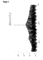
- Figure 5 shows a result where there is no sine conversion and the spurious components are clearly seen.
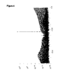
- Figure 6 shows the situation where the first embodiment of the invention is used with a digital sine lookup table and it can be seen that the spurious components are much reduced.
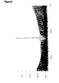
- Figure 7 shows the result for the second embodiment of the invention employing an analogue sine converter and the spurious components are substantially lower than for the digital sine converter.
Landscapes
- Engineering & Computer Science (AREA)
- Theoretical Computer Science (AREA)
- Physics & Mathematics (AREA)
- General Engineering & Computer Science (AREA)
- General Physics & Mathematics (AREA)
- Stabilization Of Oscillater, Synchronisation, Frequency Synthesizers (AREA)
- Manipulation Of Pulses (AREA)
- Analogue/Digital Conversion (AREA)
Applications Claiming Priority (2)
| Application Number | Priority Date | Filing Date | Title |
|---|---|---|---|
| GB9616537 | 1996-08-06 | ||
| GBGB9616537.8A GB9616537D0 (en) | 1996-08-06 | 1996-08-06 | Digital synthesiser |
Publications (2)
| Publication Number | Publication Date |
|---|---|
| EP0823700A2 true EP0823700A2 (de) | 1998-02-11 |
| EP0823700A3 EP0823700A3 (de) | 1998-09-23 |
Family
ID=10798118
Family Applications (1)
| Application Number | Title | Priority Date | Filing Date |
|---|---|---|---|
| EP97305750A Withdrawn EP0823700A3 (de) | 1996-08-06 | 1997-07-30 | Digitales Synthesegerät |
Country Status (3)
| Country | Link |
|---|---|
| US (1) | US5977804A (de) |
| EP (1) | EP0823700A3 (de) |
| GB (1) | GB9616537D0 (de) |
Cited By (6)
| Publication number | Priority date | Publication date | Assignee | Title |
|---|---|---|---|---|
| WO2001018637A1 (de) * | 1999-09-02 | 2001-03-15 | Siemens Aktiengesellschaft | Verbesserung der spektralen eigenschaften bei einer direkten digitalen frequenzsynthese |
| EP1164696A4 (de) * | 1999-12-24 | 2003-07-23 | Anritsu Corp | Wandergenerator, diesen enthaltender digitaler leistungsprüfer und analysator der übertragungskennlinie von phasenrauschen |
| WO2003001673A3 (en) * | 2001-06-25 | 2003-10-23 | Rambus Inc | Determining phase relationships using digital phase values |
| EP1351397A3 (de) * | 2001-11-27 | 2005-03-02 | Texas Instruments Incorporated | Volldigitale Frequenzsynthese mit kapazitiver Rückführung von gezitterten Abstimmdaten |
| WO2005048089A1 (de) * | 2003-11-05 | 2005-05-26 | Rohde & Schwarz Gmbh & Co. Kg | Frequenzsynthesizer nach dem direkten digitalen synthese-verfahren |
| US7046098B2 (en) | 2001-11-27 | 2006-05-16 | Texas Instruments Incorporated | All-digital frequency synthesis with capacitive re-introduction of dithered tuning information |
Families Citing this family (15)
| Publication number | Priority date | Publication date | Assignee | Title |
|---|---|---|---|---|
| FR2793972B1 (fr) * | 1999-05-21 | 2001-08-10 | Thomson Csf | Synthetiseur numerique a division coherente |
| US6229400B1 (en) * | 1999-10-22 | 2001-05-08 | Motorola Inc. | Method and apparatus for a calibrated frequency modulation phase locked loop |
| US7495516B2 (en) * | 2003-04-02 | 2009-02-24 | Christopher Julian Travis | Method of establishing an oscillator clock signal |
| KR100973725B1 (ko) * | 2003-07-25 | 2010-08-04 | 트랜스퍼시픽 소닉, 엘엘씨 | Dds를 이용한 클럭 발생 장치 |
| US7421464B2 (en) * | 2004-09-30 | 2008-09-02 | Motorola, Inc. | System and method for introducing dither for reducing spurs in digital-to-time converter direct digital synthesis |
| US9679602B2 (en) | 2006-06-14 | 2017-06-13 | Seagate Technology Llc | Disc drive circuitry swap |
| CA2671731A1 (en) * | 2007-01-04 | 2008-07-17 | Qualcomm Incorporated | Method and apparatus for distributed spectrum sensing for wireless communication |
| US9305590B2 (en) | 2007-10-16 | 2016-04-05 | Seagate Technology Llc | Prevent data storage device circuitry swap |
| US7557619B1 (en) * | 2008-03-10 | 2009-07-07 | Xilinx, Inc. | Digital frequency synthesis |
| US8537772B2 (en) * | 2009-07-02 | 2013-09-17 | Qualcomm Incorporated | Transmitter quieting during spectrum sensing |
| US8780982B2 (en) * | 2009-07-02 | 2014-07-15 | Qualcomm Incorporated | Transmitter quieting and different encoding rates for portions of a set of frames |
| US8958475B2 (en) * | 2009-07-02 | 2015-02-17 | Qualcomm Incorporated | Transmitter quieting and null data encoding |
| US8902995B2 (en) * | 2009-07-02 | 2014-12-02 | Qualcomm Incorporated | Transmitter quieting and reduced rate encoding |
| US9112618B2 (en) * | 2009-07-02 | 2015-08-18 | Qualcomm Incorporated | Coding latency reductions during transmitter quieting |
| US20110182257A1 (en) * | 2010-01-26 | 2011-07-28 | Qualcomm Incorporated | White space spectrum commmunciation device with multiplexing capabilties |
Family Cites Families (4)
| Publication number | Priority date | Publication date | Assignee | Title |
|---|---|---|---|---|
| US4901265A (en) * | 1987-12-14 | 1990-02-13 | Qualcomm, Inc. | Pseudorandom dither for frequency synthesis noise |
| US4951237A (en) * | 1988-04-22 | 1990-08-21 | Hughes Aircraft Company | Direct digital synthesizer with selectably randomized accumulator |
| US5073869A (en) * | 1989-08-25 | 1991-12-17 | Titan Linkabit Corporation | Suppression of spurious frequency components in direct digital frequency synthesizer |
| US5291428A (en) * | 1993-03-02 | 1994-03-01 | Harris Corporation | Apparatus for reducing spurious frequency components in the output signal of a direct digital synthesizer |
-
1996
- 1996-08-06 GB GBGB9616537.8A patent/GB9616537D0/en active Pending
-
1997
- 1997-07-30 EP EP97305750A patent/EP0823700A3/de not_active Withdrawn
- 1997-08-04 US US08/905,661 patent/US5977804A/en not_active Expired - Fee Related
Cited By (10)
| Publication number | Priority date | Publication date | Assignee | Title |
|---|---|---|---|---|
| WO2001018637A1 (de) * | 1999-09-02 | 2001-03-15 | Siemens Aktiengesellschaft | Verbesserung der spektralen eigenschaften bei einer direkten digitalen frequenzsynthese |
| EP1164696A4 (de) * | 1999-12-24 | 2003-07-23 | Anritsu Corp | Wandergenerator, diesen enthaltender digitaler leistungsprüfer und analysator der übertragungskennlinie von phasenrauschen |
| US7206339B2 (en) | 1999-12-24 | 2007-04-17 | Anritsu Corporation | Wonder generator, digital line tester comprising the same, and phase noise transfer characteristic analyzer |
| US7450633B2 (en) | 1999-12-24 | 2008-11-11 | Anritsu Corporation | Wander generator, and digital line tester and phase noise transfer characteristic analyzer using the same |
| WO2003001673A3 (en) * | 2001-06-25 | 2003-10-23 | Rambus Inc | Determining phase relationships using digital phase values |
| US7194056B2 (en) | 2001-06-25 | 2007-03-20 | Rambus Inc. | Determining phase relationships using digital phase values |
| EP1351397A3 (de) * | 2001-11-27 | 2005-03-02 | Texas Instruments Incorporated | Volldigitale Frequenzsynthese mit kapazitiver Rückführung von gezitterten Abstimmdaten |
| US7046098B2 (en) | 2001-11-27 | 2006-05-16 | Texas Instruments Incorporated | All-digital frequency synthesis with capacitive re-introduction of dithered tuning information |
| WO2005048089A1 (de) * | 2003-11-05 | 2005-05-26 | Rohde & Schwarz Gmbh & Co. Kg | Frequenzsynthesizer nach dem direkten digitalen synthese-verfahren |
| US7242225B2 (en) | 2003-11-05 | 2007-07-10 | Rohde & Schwarz Gmbh & Co. Kg | Direct digital frequency synthesizer |
Also Published As
| Publication number | Publication date |
|---|---|
| GB9616537D0 (en) | 1996-09-25 |
| EP0823700A3 (de) | 1998-09-23 |
| US5977804A (en) | 1999-11-02 |
Similar Documents
| Publication | Publication Date | Title |
|---|---|---|
| US5977804A (en) | Digital synthesizer | |
| US5598440A (en) | DDS driven DDS synthesizer for generating sinewave waveforms with reduced spurious signal levels | |
| US4901265A (en) | Pseudorandom dither for frequency synthesis noise | |
| Flanagan et al. | Spur-reduced digital sinusoid synthesis | |
| US5014231A (en) | Randomized digital/analog converter direct digital synthesizer | |
| US5459680A (en) | Method and apparatus for spur-reduced digital sinusoid synthesis | |
| US6226661B1 (en) | Generation and application of sample rate conversion ratios using distributed jitter | |
| US6262604B1 (en) | Digital synthesizer of signals | |
| US7324030B2 (en) | Multiple stage delta sigma modulators | |
| KR100434207B1 (ko) | 인코딩장치와방법및디코딩장치와방법 | |
| US6515601B2 (en) | Noise shaper | |
| US6785345B2 (en) | Frequency dithering for DDS spectral purity | |
| EP0782062B1 (de) | Rauschverminderung in digitalen Frequenzsynthetisierern | |
| JP4058174B2 (ja) | 信号処理装置 | |
| US5892692A (en) | Method for generating a lookup table for a digital oscillator | |
| US6563393B2 (en) | Method and device for pulse density modulation | |
| HK1009021A (en) | Digital syntesizer | |
| JP4058175B2 (ja) | 音声信号処理装置 | |
| US7026846B1 (en) | Synthesizer structures and methods that reduce spurious signals | |
| US5936438A (en) | Digital oscillator using lookup table with multiple cycles | |
| US6577910B1 (en) | Digital audio signal processors | |
| US6518802B1 (en) | Circuits and methods for generating an accurate digital representation of a sinusoidal wave | |
| US5602874A (en) | Method and apparatus for reducing quantization noise | |
| US5619002A (en) | Tone production method and apparatus for electronic music | |
| Sadat Noori et al. | A novel structure of dithered nested digital delta sigma modulator with low-complexity low-spur for fractional frequency synthesizers |
Legal Events
| Date | Code | Title | Description |
|---|---|---|---|
| PUAI | Public reference made under article 153(3) epc to a published international application that has entered the european phase |
Free format text: ORIGINAL CODE: 0009012 |
|
| AK | Designated contracting states |
Kind code of ref document: A2 Designated state(s): DE FR GB IT |
|
| PUAL | Search report despatched |
Free format text: ORIGINAL CODE: 0009013 |
|
| AK | Designated contracting states |
Kind code of ref document: A3 Designated state(s): AT BE CH DE DK ES FI FR GB GR IE IT LI LU MC NL PT SE |
|
| 17P | Request for examination filed |
Effective date: 19990323 |
|
| AKX | Designation fees paid |
Free format text: DE FR GB IT |
|
| RBV | Designated contracting states (corrected) |
Designated state(s): DE FR GB IT |
|
| STAA | Information on the status of an ep patent application or granted ep patent |
Free format text: STATUS: THE APPLICATION IS DEEMED TO BE WITHDRAWN |
|
| 18D | Application deemed to be withdrawn |
Effective date: 20010201 |
|
| REG | Reference to a national code |
Ref country code: HK Ref legal event code: WD Ref document number: 1009021 Country of ref document: HK |