EP0823762A1 - Eckverbindung für einen Kabelkanal - Google Patents
Eckverbindung für einen Kabelkanal Download PDFInfo
- Publication number
- EP0823762A1 EP0823762A1 EP96112615A EP96112615A EP0823762A1 EP 0823762 A1 EP0823762 A1 EP 0823762A1 EP 96112615 A EP96112615 A EP 96112615A EP 96112615 A EP96112615 A EP 96112615A EP 0823762 A1 EP0823762 A1 EP 0823762A1
- Authority
- EP
- European Patent Office
- Prior art keywords
- corner joint
- segment
- corner
- parts
- joint according
- Prior art date
- Legal status (The legal status is an assumption and is not a legal conclusion. Google has not performed a legal analysis and makes no representation as to the accuracy of the status listed.)
- Granted
Links
- 239000007787 solid Substances 0.000 claims description 12
- 230000000295 complement effect Effects 0.000 claims description 3
- 238000011010 flushing procedure Methods 0.000 claims description 2
- 238000010276 construction Methods 0.000 description 5
- 230000007704 transition Effects 0.000 description 4
- 239000012634 fragment Substances 0.000 description 2
- 230000001154 acute effect Effects 0.000 description 1
- 230000007547 defect Effects 0.000 description 1
- 238000009434 installation Methods 0.000 description 1
- 125000006850 spacer group Chemical group 0.000 description 1
Images


Classifications
-
- H—ELECTRICITY
- H02—GENERATION; CONVERSION OR DISTRIBUTION OF ELECTRIC POWER
- H02G—INSTALLATION OF ELECTRIC CABLES OR LINES, OR OF COMBINED OPTICAL AND ELECTRIC CABLES OR LINES
- H02G3/00—Installations of electric cables or lines or protective tubing therefor in or on buildings, equivalent structures or vehicles
- H02G3/02—Details
- H02G3/06—Joints for connecting lengths of protective tubing or channels, to each other or to casings, e.g. to distribution boxes; Ensuring electrical continuity in the joint
- H02G3/0608—Joints for connecting non cylindrical conduits, e.g. channels
Definitions
- the invention concerns a corner joint for a cable duct, and which has a cross section in the shape of mainly an U and consists of a body and two flanges.
- Cable ducts are used for supporting and hiding cables which are passed along the walls in a building, and also for mounting corresponding installations, as e.g. wall sockets or plug sockets. In most cases the ducts can be seen and efforts are therefore made to form them in a beautiful and attractive design.
- a cable duct is normally builded up of straight duct parts which are connected with corner joints at corners in the building. These corner joints are usually fixed components which typically are adapted to assemble the straight duct parts at a right angle in either an inner or outer building corner.
- the object of the invention is to provide a corner joint of the type mentioned in the opening paragraph which without a substantial change of the basic design easily can be adapted to fit satisfactorily for assembling straight cable parts in a corner with an angle within a pre-decided angle area.
- Another purpose of the invention is to provide a corner joint of the type mentioned in the opening paragraph which in all of the possible angle positions has a design fitting to the design of the straight duct parts.
- the corner joint comprises a segment of an annular solid of revolution which defines an axis parallel with the body and also comprises two corner joint parts which are placed after each other and pivotally around said axis is connected with as well the segment as each other.
- the two corner joint parts can thereby fit into a given corner and by mounting brought to fit tightly and smoothly to the adjoining ends of the two duct parts at the same time as the rear edges of the flanges will be flush with the walls of the corner.
- the segment of the solid of revolution forms a transition between the bodies of the corner joint parts, which bodies more or less will be removed form each other in dependence of the angle of the corner.
- the free edge, being closest to the segment, of the body of each corner joint part can be formed in such a way that it, when the corner joint part is swinging around the swivel axis, describes a face which is similar to the outside of the segment and surrounds this at a relatively small distance.
- the segment can have an adequately large arc of an angel to be able to close the largest space which can arise between the two bodies of the corner joint parts, and at the same time there can at each of the two side edges of the segment be formed an outside-turning projection to ensure that the segment continuously will be in a position in relation to the two bodies where it will be able to bridge the possible spaces between the bodies.
- the mutual swinging function of the corner parts can be established by hinging the flanges together with hinges, each of which comprising two hinge-joints and a pivot with the same axis as the solid of revolution.
- the hinge-joints can furthermore be formed as an integrated part of the respective flange whereby the construction will be especially simple.
- the hinge joints can be separate parts which then are attached to the inside of the flanges in order not to disfigure the design by being visible on the upper side of the flanges.
- each of these discs there can furthermore coaxially with the solid of revolution be formed an annular groove for slidingly to accommodate one of the ends of the segment so that the segment of the solid of revolution will be swinging around the same axis as the corner joint parts.
- each disc there can furthermore be formed incisions in the hinge joints for allowing the segment to extend freely between the grooves.
- the swivel axis can principally be placed in any position in relation to the corner join.
- An especially expedient construction can, however, be obtained when the swivel axis is cutting each plane of the flange in a point between lines containing the two longitudinal edges of the respective flange.
- corner is used for an inside or outside corner in a building.
- corner joints which are used to connect straight cable parts in such a building corner the expression “corner” is used for the sake of convenience, which expression equally can be either an inner corner or a outer corner.
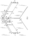
- This advantageous function is mainly obtained by building up the corner 2 of two inner corner parts 2a,b which are pivotally connected with each other and therefore can be adjusted to exactly that angle which fits to a certain building corner.
- each part 2a,b has a cross section in the shape of an U and consists of a vertical body 4 and two horizontal flanges 5.
- the body 4 overlaps in mounted condition the front plate 6 of the cable duct, while the flanges 5 are overlapping the top plate and the bottom plate 7, respectively, of the cable duct.
- the rear edge 8 of the flanges are following the walls of the building corner.
- the geometry of the construction implies that there in most of the angle positions, in which the two parts 2a,b can be placed in relation to each other, is created an opening between the two inner edges 9, turning towards each other, of the bodies 4. In deference to the general impression of the design this opening is filled out of a segment 10 of an annular solid of revolution which in the case shown is a straight tube.
- Discs 11 are let into the flanges for closing the openings which are formed in this area in most of the mutual angle positions between the two parts 2a,b.
- the discs are placed with the outside being flushed with the outside of the flanges such that the passage between the two parts will be even and smooth.
- Fig 2 shows in fragments the inner corner 2, seen from above.
- the axis of rotation 12 between the parts 2a,b is coinciding with the axis of the discs 11.
- the discs 11 formed complementary incisions 13 with only somewhat larger radius than the radius of the disc. The edges of the incisions will therefore follow the periphery of the disc 11 in close distance in all of the angle positions between the parts.
- the typical angle position of 90° is shown in fig. 2 with a full-drawn line while the positions with angles which are larger or smaller than 90°, respectively, are shown with a dotted line.
- Fig. 3 and 4 show more definite how the inner corner 2 is adapted.
- the two parts 2a,b are hinged together with hinges which consist of two hinge parts 14 and a swivel 15 which is coaxially attached to the inside of the disc 11.
- the hinge parts also can be formed as integrated parts of the flanges themselves.
- the incisions are replaced by depressions in the flanges with the same outline as the edges of the recesses such that the hinges will be offset under the disc.
- the variant is not shown in the drawing.
- each of the insides of the discs 11 there is formed a groove 16 which serves to slidingly accommodating one of the ends of the tube segment 10.
- the outside of the tube segment 10 will be situated in a cylinder surface with radius r1 and axis in common with the axis of revolution 12 of the parts 2a,b.
- the radius r2 of the cylinder surface is only somewhat larger than r1 and the inner edges 9 of the bodies will therefore follow the outside of the tube segment at close distance in all of the angle position between the parts.
- the tube segment has to span an arc of an angel which at least is just as large as the angle between the to inner edges in the largest angle position between the parts 2a,b. It is, however, for constructive reasons not expedient that the arc of angel of the segment becomes too big, and to ensure that the segment continuously can bridge the opening between the inner edges 9 there has therefore at each of the side edges of the segment been formed an inwards turning projection 17 to prevent, by stopping against the inside of the corresponding body, that the segment is rotating past the inner edge 9 of one of the bodies and is exposing an opening at this edge.
- the hinges parts 14a,b are, a.o. in deference to the look, placed upon the inside of the flanges and under the disc. In the hinge parts 14 there have therefore been made incisions 18 which allow the segment 10 to extend freely between the grooves 16 of the discs 11.
- the discs are by means of screw connections (not shown) or in another expedient way attached to the flanges with intermediate spacers 18. Furthermore, the hinge parts are pivotally fixed on the tap 15 by means of a screw 20 and a disc 21 and also a pressure spring 22 to tighten the hinge parts 14 against the underside of the disc to ensure that the two parts 2a,b in every angle position can form a stiff and non-backlash connection with each other.
- Fig. 5 - 8 show an outer building corner 23 where an outer corner 24 for a cable duct is used to assemble two straight cable duct parts 3.
- this outer corner 24 fits for an outer building corner, while the geometry of the inner corner 2 fits for an inner building corner, but otherwise the two corners are in principle adapted in the same way and similar parts are therefore designated with the same reference number. Since the two corners furthermore functions in the same way and fulfil the same purpose there can, as regards to the outer corner 24 shown in fig. 5 - 8, be referred to the above disclosed description of the inner corner 2 shown in fig. 1 - 4.
- the distance of the intersection point from the line through the rear edges 8 of the flanges will typically be larger as regards the inner corner 2 than as regards the outer corner 24.
- the cable duct has a diagonal front face, there will have to be used an annular truncated cone segment. If the front face is arched, there will correspondingly have to be used an annular solid of revolution with a generatrix which in the shape corresponds to the arched form of the front face.
- the corner joint can also be used to assemble two cable duct parts which form an angle to a horizontal plane.
- the inner edges of the bodies shall not be perpendicular to the flanges, as shown in fig. 1 and 5, but form an acute angle which corresponds to the angle which the cable duct forms with a horizontal plane.
Landscapes
- Engineering & Computer Science (AREA)
- Architecture (AREA)
- Civil Engineering (AREA)
- Structural Engineering (AREA)
- Details Of Indoor Wiring (AREA)
- Laying Of Electric Cables Or Lines Outside (AREA)
- Surgical Instruments (AREA)
- Transition And Organic Metals Composition Catalysts For Addition Polymerization (AREA)
- Separation By Low-Temperature Treatments (AREA)
Priority Applications (4)
| Application Number | Priority Date | Filing Date | Title |
|---|---|---|---|
| AT96112615T ATE190438T1 (de) | 1996-08-05 | 1996-08-05 | Eckverbindung für einen kabelkanal |
| EP96112615A EP0823762B1 (de) | 1996-08-05 | 1996-08-05 | Eckverbindung für einen Kabelkanal |
| DE69606990T DE69606990T2 (de) | 1996-08-05 | 1996-08-05 | Eckverbindung für einen Kabelkanal |
| DK96112615T DK0823762T3 (da) | 1996-08-05 | 1996-08-05 | Hjørnesamling |
Applications Claiming Priority (1)
| Application Number | Priority Date | Filing Date | Title |
|---|---|---|---|
| EP96112615A EP0823762B1 (de) | 1996-08-05 | 1996-08-05 | Eckverbindung für einen Kabelkanal |
Publications (2)
| Publication Number | Publication Date |
|---|---|
| EP0823762A1 true EP0823762A1 (de) | 1998-02-11 |
| EP0823762B1 EP0823762B1 (de) | 2000-03-08 |
Family
ID=8223077
Family Applications (1)
| Application Number | Title | Priority Date | Filing Date |
|---|---|---|---|
| EP96112615A Expired - Lifetime EP0823762B1 (de) | 1996-08-05 | 1996-08-05 | Eckverbindung für einen Kabelkanal |
Country Status (4)
| Country | Link |
|---|---|
| EP (1) | EP0823762B1 (de) |
| AT (1) | ATE190438T1 (de) |
| DE (1) | DE69606990T2 (de) |
| DK (1) | DK0823762T3 (de) |
Cited By (4)
| Publication number | Priority date | Publication date | Assignee | Title |
|---|---|---|---|---|
| FR2861906A1 (fr) * | 2003-11-05 | 2005-05-06 | Legrand Sa | Accessoire d'angle pour goulottes comprenant deux volets assembles en biais |
| US20130000097A1 (en) * | 2011-06-29 | 2013-01-03 | Pino Angelo J | Raceway molding system device and method |
| CN107154600A (zh) * | 2017-04-30 | 2017-09-12 | 陶霞霞 | 一种特高压电缆铺设过程中判断电缆是否伸直的方法 |
| EP3540883A1 (de) | 2018-03-16 | 2019-09-18 | Niedax GmbH & Co. KG | Kabelführungsverbinder und verfahren zum verbinden von kabelführungselementen |
Citations (3)
| Publication number | Priority date | Publication date | Assignee | Title |
|---|---|---|---|---|
| US1425011A (en) * | 1920-05-12 | 1922-08-08 | Reflector & Illuminating Co | Joint for electrical conduits |
| US2899159A (en) * | 1959-08-11 | Cable support structure | ||
| US4096349A (en) * | 1977-04-04 | 1978-06-20 | Lightolier Incorporated | Flexible connector for track lighting systems |
-
1996
- 1996-08-05 EP EP96112615A patent/EP0823762B1/de not_active Expired - Lifetime
- 1996-08-05 DK DK96112615T patent/DK0823762T3/da active
- 1996-08-05 DE DE69606990T patent/DE69606990T2/de not_active Expired - Fee Related
- 1996-08-05 AT AT96112615T patent/ATE190438T1/de not_active IP Right Cessation
Patent Citations (3)
| Publication number | Priority date | Publication date | Assignee | Title |
|---|---|---|---|---|
| US2899159A (en) * | 1959-08-11 | Cable support structure | ||
| US1425011A (en) * | 1920-05-12 | 1922-08-08 | Reflector & Illuminating Co | Joint for electrical conduits |
| US4096349A (en) * | 1977-04-04 | 1978-06-20 | Lightolier Incorporated | Flexible connector for track lighting systems |
Cited By (7)
| Publication number | Priority date | Publication date | Assignee | Title |
|---|---|---|---|---|
| FR2861906A1 (fr) * | 2003-11-05 | 2005-05-06 | Legrand Sa | Accessoire d'angle pour goulottes comprenant deux volets assembles en biais |
| EP1530273A1 (de) * | 2003-11-05 | 2005-05-11 | Legrand | Winkelzubehörelement für Führungskanäle mit zwei in die Quere zusammengefügten Flügeln |
| US7198423B2 (en) | 2003-11-05 | 2007-04-03 | Legrand France | Skirting duct angle accessory comprising two flaps assembled together at an angle |
| US20130000097A1 (en) * | 2011-06-29 | 2013-01-03 | Pino Angelo J | Raceway molding system device and method |
| CN107154600A (zh) * | 2017-04-30 | 2017-09-12 | 陶霞霞 | 一种特高压电缆铺设过程中判断电缆是否伸直的方法 |
| CN107154600B (zh) * | 2017-04-30 | 2019-04-19 | 广东良实机电工程有限公司 | 一种特高压电缆铺设过程中判断电缆是否伸直的方法 |
| EP3540883A1 (de) | 2018-03-16 | 2019-09-18 | Niedax GmbH & Co. KG | Kabelführungsverbinder und verfahren zum verbinden von kabelführungselementen |
Also Published As
| Publication number | Publication date |
|---|---|
| EP0823762B1 (de) | 2000-03-08 |
| DE69606990D1 (de) | 2000-04-13 |
| DE69606990T2 (de) | 2000-11-16 |
| ATE190438T1 (de) | 2000-03-15 |
| DK0823762T3 (da) | 2000-11-20 |
Similar Documents
| Publication | Publication Date | Title |
|---|---|---|
| US6223393B1 (en) | Redundant hinge element for a notebook computer | |
| AU2006213013B2 (en) | Valve assembly | |
| US5686700A (en) | Adjustable cable management grommet | |
| RU2410011C2 (ru) | Эксцентрическая петля для сантехнического устройства | |
| US5363616A (en) | Adjustable corner mullion for joining building panels | |
| CN1223024A (zh) | 用于管道系统的外角管接头 | |
| EP0823762B1 (de) | Eckverbindung für einen Kabelkanal | |
| US7041901B2 (en) | Method and apparatus for providing an environmental barrier between an interior and exterior of an electrical enclosure using a plug and seal | |
| KR200499241Y1 (ko) | 힌지 및 이것을 사용하는 전자 장치 | |
| FR2704811B1 (fr) | Articulation de dossier pour un siège de véhicule avec un support de siège et un dossier articulé à celui-ci. | |
| JP5118387B2 (ja) | 四節リンク式隠し丁番 | |
| WO1992019901A1 (en) | An adjustable pipe bend for drain pipes | |
| KR102225621B1 (ko) | 감시카메라용 지지 브라켓 | |
| GB2366929A (en) | Surveillance camera with rotating lens | |
| JP2906345B2 (ja) | フレキシブルパーティションにおけるパネル材の連結構造 | |
| USD375888S (en) | Resilient spider for well installation | |
| JP2906344B2 (ja) | フレキシブルパーティションにおけるパネル材の連結構造 | |
| GB2073543A (en) | Loudspeaker holding device | |
| GB2278152A (en) | Hinge | |
| TWI722563B (zh) | 嵌入式截火裝置、使用該裝置的方法及用於該裝置的固定盤 | |
| FR2704914B1 (fr) | Partie extérieure de joint pour un joint tripode. | |
| JP3385396B2 (ja) | 流体管継手支持ボックス | |
| JP4799258B2 (ja) | エキスパンションジョイント構造 | |
| JP3080764B2 (ja) | 軒樋と竪樋の接続構造 | |
| JP2683716B2 (ja) | エアコン用冷媒管ジョイント部保護カバー |
Legal Events
| Date | Code | Title | Description |
|---|---|---|---|
| PUAI | Public reference made under article 153(3) epc to a published international application that has entered the european phase |
Free format text: ORIGINAL CODE: 0009012 |
|
| AK | Designated contracting states |
Kind code of ref document: A1 Designated state(s): AT BE CH DE DK ES FI FR GB GR IE IT LI NL PT SE |
|
| 17P | Request for examination filed |
Effective date: 19980312 |
|
| 17Q | First examination report despatched |
Effective date: 19980507 |
|
| AKX | Designation fees paid |
Free format text: AT BE CH DE DK ES FI FR GB GR IE IT LI NL PT SE |
|
| RBV | Designated contracting states (corrected) |
Designated state(s): AT BE CH DE DK ES FI FR GB GR IE IT LI NL PT SE |
|
| GRAG | Despatch of communication of intention to grant |
Free format text: ORIGINAL CODE: EPIDOS AGRA |
|
| GRAG | Despatch of communication of intention to grant |
Free format text: ORIGINAL CODE: EPIDOS AGRA |
|
| GRAG | Despatch of communication of intention to grant |
Free format text: ORIGINAL CODE: EPIDOS AGRA |
|
| GRAH | Despatch of communication of intention to grant a patent |
Free format text: ORIGINAL CODE: EPIDOS IGRA |
|
| GRAH | Despatch of communication of intention to grant a patent |
Free format text: ORIGINAL CODE: EPIDOS IGRA |
|
| GRAA | (expected) grant |
Free format text: ORIGINAL CODE: 0009210 |
|
| AK | Designated contracting states |
Kind code of ref document: B1 Designated state(s): AT BE CH DE DK ES FI FR GB GR IE IT LI NL PT SE |
|
| PG25 | Lapsed in a contracting state [announced via postgrant information from national office to epo] |
Ref country code: NL Free format text: LAPSE BECAUSE OF FAILURE TO SUBMIT A TRANSLATION OF THE DESCRIPTION OR TO PAY THE FEE WITHIN THE PRESCRIBED TIME-LIMIT Effective date: 20000308 Ref country code: LI Free format text: LAPSE BECAUSE OF NON-PAYMENT OF DUE FEES Effective date: 20000308 Ref country code: IT Free format text: LAPSE BECAUSE OF FAILURE TO SUBMIT A TRANSLATION OF THE DESCRIPTION OR TO PAY THE FEE WITHIN THE PRE;WARNING: LAPSES OF ITALIAN PATENTS WITH EFFECTIVE DATE BEFORE 2007 MAY HAVE OCCURRED AT ANY TIME BEFORE 2007. THE CORRECT EFFECTIVE DATE MAY BE DIFFERENT FROM THE ONE RECORDED.SCRIBED TIME-LIMIT Effective date: 20000308 Ref country code: GR Free format text: LAPSE BECAUSE OF NON-PAYMENT OF DUE FEES Effective date: 20000308 Ref country code: FR Free format text: LAPSE BECAUSE OF FAILURE TO SUBMIT A TRANSLATION OF THE DESCRIPTION OR TO PAY THE FEE WITHIN THE PRESCRIBED TIME-LIMIT Effective date: 20000308 Ref country code: ES Free format text: THE PATENT HAS BEEN ANNULLED BY A DECISION OF A NATIONAL AUTHORITY Effective date: 20000308 Ref country code: CH Free format text: LAPSE BECAUSE OF NON-PAYMENT OF DUE FEES Effective date: 20000308 Ref country code: BE Free format text: LAPSE BECAUSE OF FAILURE TO SUBMIT A TRANSLATION OF THE DESCRIPTION OR TO PAY THE FEE WITHIN THE PRESCRIBED TIME-LIMIT Effective date: 20000308 Ref country code: AT Free format text: LAPSE BECAUSE OF FAILURE TO SUBMIT A TRANSLATION OF THE DESCRIPTION OR TO PAY THE FEE WITHIN THE PRESCRIBED TIME-LIMIT Effective date: 20000308 |
|
| REF | Corresponds to: |
Ref document number: 190438 Country of ref document: AT Date of ref document: 20000315 Kind code of ref document: T |
|
| REG | Reference to a national code |
Ref country code: CH Ref legal event code: EP |
|
| REF | Corresponds to: |
Ref document number: 69606990 Country of ref document: DE Date of ref document: 20000413 |
|
| REG | Reference to a national code |
Ref country code: IE Ref legal event code: FG4D |
|
| PG25 | Lapsed in a contracting state [announced via postgrant information from national office to epo] |
Ref country code: PT Free format text: LAPSE BECAUSE OF FAILURE TO SUBMIT A TRANSLATION OF THE DESCRIPTION OR TO PAY THE FEE WITHIN THE PRESCRIBED TIME-LIMIT Effective date: 20000608 |
|
| NLV1 | Nl: lapsed or annulled due to failure to fulfill the requirements of art. 29p and 29m of the patents act | ||
| EN | Fr: translation not filed | ||
| REG | Reference to a national code |
Ref country code: CH Ref legal event code: PL |
|
| REG | Reference to a national code |
Ref country code: DK Ref legal event code: T3 |
|
| PLBE | No opposition filed within time limit |
Free format text: ORIGINAL CODE: 0009261 |
|
| STAA | Information on the status of an ep patent application or granted ep patent |
Free format text: STATUS: NO OPPOSITION FILED WITHIN TIME LIMIT |
|
| 26N | No opposition filed | ||
| REG | Reference to a national code |
Ref country code: GB Ref legal event code: IF02 |
|
| PGFP | Annual fee paid to national office [announced via postgrant information from national office to epo] |
Ref country code: GB Payment date: 20020731 Year of fee payment: 7 |
|
| PGFP | Annual fee paid to national office [announced via postgrant information from national office to epo] |
Ref country code: SE Payment date: 20020806 Year of fee payment: 7 |
|
| PGFP | Annual fee paid to national office [announced via postgrant information from national office to epo] |
Ref country code: FI Payment date: 20020814 Year of fee payment: 7 Ref country code: DK Payment date: 20020814 Year of fee payment: 7 |
|
| PGFP | Annual fee paid to national office [announced via postgrant information from national office to epo] |
Ref country code: DE Payment date: 20020816 Year of fee payment: 7 |
|
| PGFP | Annual fee paid to national office [announced via postgrant information from national office to epo] |
Ref country code: IE Payment date: 20020827 Year of fee payment: 7 |
|
| PG25 | Lapsed in a contracting state [announced via postgrant information from national office to epo] |
Ref country code: IE Free format text: LAPSE BECAUSE OF NON-PAYMENT OF DUE FEES Effective date: 20030805 Ref country code: GB Free format text: LAPSE BECAUSE OF NON-PAYMENT OF DUE FEES Effective date: 20030805 Ref country code: FI Free format text: LAPSE BECAUSE OF NON-PAYMENT OF DUE FEES Effective date: 20030805 |
|
| PG25 | Lapsed in a contracting state [announced via postgrant information from national office to epo] |
Ref country code: SE Free format text: LAPSE BECAUSE OF NON-PAYMENT OF DUE FEES Effective date: 20030806 |
|
| PG25 | Lapsed in a contracting state [announced via postgrant information from national office to epo] |
Ref country code: DK Free format text: LAPSE BECAUSE OF NON-PAYMENT OF DUE FEES Effective date: 20030901 |
|
| PG25 | Lapsed in a contracting state [announced via postgrant information from national office to epo] |
Ref country code: DE Free format text: LAPSE BECAUSE OF NON-PAYMENT OF DUE FEES Effective date: 20040302 |
|
| GBPC | Gb: european patent ceased through non-payment of renewal fee |
Effective date: 20030805 |
|
| EUG | Se: european patent has lapsed | ||
| REG | Reference to a national code |
Ref country code: DK Ref legal event code: EBP |
|
| REG | Reference to a national code |
Ref country code: IE Ref legal event code: MM4A |