EP0823834A2 - Einbaumodul - Google Patents
Einbaumodul Download PDFInfo
- Publication number
- EP0823834A2 EP0823834A2 EP97810478A EP97810478A EP0823834A2 EP 0823834 A2 EP0823834 A2 EP 0823834A2 EP 97810478 A EP97810478 A EP 97810478A EP 97810478 A EP97810478 A EP 97810478A EP 0823834 A2 EP0823834 A2 EP 0823834A2
- Authority
- EP
- European Patent Office
- Prior art keywords
- module
- built
- counterparts
- plug
- installation module
- Prior art date
- Legal status (The legal status is an assumption and is not a legal conclusion. Google has not performed a legal analysis and makes no representation as to the accuracy of the status listed.)
- Withdrawn
Links
Images
Classifications
-
- H—ELECTRICITY
- H05—ELECTRIC TECHNIQUES NOT OTHERWISE PROVIDED FOR
- H05K—PRINTED CIRCUITS; CASINGS OR CONSTRUCTIONAL DETAILS OF ELECTRIC APPARATUS; MANUFACTURE OF ASSEMBLAGES OF ELECTRICAL COMPONENTS
- H05K5/00—Casings, cabinets or drawers for electric apparatus
- H05K5/30—Side-by-side or stacked arrangements
-
- H—ELECTRICITY
- H05—ELECTRIC TECHNIQUES NOT OTHERWISE PROVIDED FOR
- H05K—PRINTED CIRCUITS; CASINGS OR CONSTRUCTIONAL DETAILS OF ELECTRIC APPARATUS; MANUFACTURE OF ASSEMBLAGES OF ELECTRICAL COMPONENTS
- H05K7/00—Constructional details common to different types of electric apparatus
- H05K7/14—Mounting supporting structure in casing or on frame or rack
- H05K7/1438—Back panels or connecting means therefor; Terminals; Coding means to avoid wrong insertion
- H05K7/1439—Back panel mother boards
- H05K7/1441—Back panel mother boards with a segmented structure
Definitions
- the invention relates to a closed, stable Protective housing or partially open support element with Front panel formed module, which becomes a self-supporting Module structure stackable and / or built into a frame is for electrical and electronic components and devices with at least one paired connector for electrical or optical conductors.
- Both as a protective housing and as support elements with Front panel trained modules are in numerous designs known per se, including variants with Accessible pull-out drawers.
- a first variant of the module with a closed, stable Protective housing is used in extreme mechanical, chemical and / or climatic stresses used.
- the preferably made of light metal, in particular aluminum Housing is used to shield the electronic Assemblies against high-frequency interference from external fields, but also protects against dust and water. For example, this is when used for military purposes, on commercial vehicles, important in mining, etc.
- the module can be used under normal conditions also as a partially open support element with a Front plate be formed, which can be installed in a frame is.
- the front panel can be fixed to the rack Screwed frame or as a drawer with preferably telescopic rails can be pulled out what the modules freely accessible.
- In the front panel are more common Way operating and display organs arranged.
- the invention has for its object a built-in module of the type mentioned at the beginning, which from the back emerging electrical or optical conductors largely or completely avoids plug connections practically prevented and easy to use is.
- the object is achieved according to the invention in that the Plug connections of a built-in module at a lateral distance on two parallel, sloping levels next to each other or on one running parallel to the rear of the built-in module Level are arranged, with at least one of the counterparts for plugging into the corresponding other counterpart of an adjacent installation module along the relevant one Level can be moved into a lockable position.
- the two counterparts of the plug connection must be inclined in this way be that they or their extensions are next to each other. In practice this is the case when the angle of inclination a compared to the back of the module at least about Is 10 °. On the other hand, this angle a should not be greater than about 45 °, because otherwise more and more installation space for the Electronics inside the module would be lost.
- the lateral distance between the two counterparts of the connector is also appropriate because of the space utilization at a maximum of about 20 mm.
- the counterparts at an installation module equipped with sufficient installation space on a plane running parallel to the rear wall be arranged.
- one can be plugged in Slidable counterpart of stacked installation modules cannot be positioned with simple means. Moving can be done manually e.g. after taking off the Stack at the point in question or with one by one Housing slot guided tool done. Is complicated the use of motor or electromagnetic displacement forces for a moving counterpart.
- the counterparts of the connector are preferably as Plug and socket, pin and socket strip or as Female connectors designed.
- the actual contacts are as nested pins and sockets or as pressed together Contact plate formed.
- the plug can contain pins or sockets as well as the socket Sockets or pins.
- the Plug connections When assembling or disassembling a module structure, the Plug connections in stages by moving and locking of the sliding counterpart manufactured or solved. A characteristic border and / or coding of the counterparts can ensure that the built-in modules stacked on top of each other in the planned order and the right plug connections are made.
- the neighboring modules When replacing an installation module, the neighboring modules are removed, each with a previous one Solution of the plug connection. After a variant you can the plug connections are made and removed from the outside e.g. through the back. After loosening the concerned Plug connections are individual extension modules or any drawers can be pulled out.
- the built-in modules according to the invention are for mature Applications. In the experimental stage for a new development the numerous electrical conductors will continue accepted because they can be changed at any time can.
- Built-in modules used under normal conditions can easily be screwed into a module structure or be installed adjacent to each other in a frame. In a more corrosive way and / or a humid atmosphere are preferably closed, stable protective housing used.
- This too built-in modules stacked in a module structure are useful stable protective housing made of light metal, in particular Aluminum.
- When there is a risk of shock or vibration are additionally preferably four on a base plate stored elastic buffer provided. These are on the Corners mounted diagonally inwards and with the lowest Installation module connected.
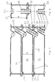
- FIG. 1 Figure 10 shows two fully and two partially shown Installation modules 12, which have a closed, stable protective housing 14 with a front side 16 and a rear side 18 includes.
- the protective housing 14 has one free installation space for electronics with a width of 270 mm, a height of 42 mm and a depth of 220 mm.
- the corresponding External dimensions for the built-in module are 300 x 300 x 60 mm. These dimensions can span a wide range can be varied.
- EMI electromagnetic interference
- each installation module 12 In the area of the rear side 18 of each installation module 12 is on parallel inclined planes E1, E2 each have a counterpart 30, e.g. one plug, and 32, e.g. an outlet, arranged.
- the counterparts 30, 32 are a ZIF connector with 156 poles. They are not recognizable in cross section in FIG. 1 elongated rectangular.
- the first counterpart 30, drawn as a plug, runs with little play in a connector sleeve 34 with guiding properties, it can be moved along the planes E1, E2.
- the Plug has a guide pin 36 protruding on both sides with a locking cam 38.
- the second counterpart 32 drawn as a socket, has a bore 40 for the guide pin 36 with a longitudinal Groove for the locking cam 38. Adjacent to the blind end of the bore 40 formed as a blind hole an annular groove recessed from the bore wall, in which of the locking cams 38 when reaching the end position of the plug 30 can be rotated. This ring groove can move in the direction pointing away from the longitudinal groove narrow so that the locking cam 38 when rotating of the guide pin 36 is jammed in the end position and sits tight.
- the guide pin 36 has at the upper end 42 a slot for a screwdriver, a hexagon hole for an Allen key or a hexagon head for one appropriate socket wrench. With one of these tools can the connector 30, preferably against the resistance pressed down by at least one spring 44 (FIG. 4) and locked by turning.
- the parallel inclined planes E1, E2 have compared to the Back 18 an angle of inclination ⁇ of about 30 °.
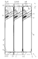
- FIG. 2 shows three built-in modules 12 screwed together combined into a module structure 10.
- the inventive Plug connections from two counterparts 30, 32 are in turn arranged on two parallel inclined planes E1, E2.
- the inclination of the levels is one with respect to the rear side 18 Installation module 12 again about 30 °, but the plugs are at Establish the plug connection in the direction of the rear side 18 of the built-in module 12.
- the connector is routed however, not through the plug sleeve 34, but via a telescopic guide 46 with two springs 44 as a return element.
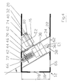
- the plug connections with the counterparts 30, 32 are in Fig. 4 shown in detail.
- the protective housing 14 can be dismantled.
- the floor 22 is welded to a lower guide frame 48 which a guide comb that tapers down sharply 28 has.
- the removable cover 20 comprises an upper one Guide frame 50 with the circular cross section at the bottom, circumferential groove 24 which contains the EMI seal 26.
- the front 16 and the rear 18 are via plug pins 52 supported.
- the front 16 In the front 16 are controls in the usual way 54 and / or display elements 56 integrated. Of course can be arranged as desired, but also completely omitted be.
- the back 18 is at least partially perforated through holes 58. Their diameter of about 2 mm isolates electromagnetic waves up to about 1 GHz.
- the module structure 10 according to FIG. 2 in the uppermost built-in module 12 a magnetic, not shown Sealing, additional for the lowest built-in module 12 a shock absorber and vibration protection in the form of elastic Have buffers.
- the module structure 2 also in a protective box with a Swing frame can be mounted, as is the case with the appreciation of the known prior art.
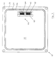
- FIG 3 shows a top view of a built-in module 12 according to FIG 2, in which in particular the square cover 20th is shown.
- the groove 24 recessed along the circumference contains the EMI seal 26.
- the groove 24 also serves as a guide groove for stacking the built-in modules 12 and is with the guide comb 28 (Fig. 1, 2) designed as a Passitz.
- Fig. 1, 2 designed as a Passitz.
- One on top of the other Installation modules 12 are in the corner area with each other connected.
- a socket strip Through an elongated opening 62 in the lid 20 that is permanently mounted counterpart 32 of the plug connection, a socket strip, recognizable.
- the electrical contacts 64 can however not only as sockets, but also as pins or Contact plate be formed.
- the other counterpart 30 (Fig. 1, 2) is designed accordingly.
- a bore 66 in the cover 20 serves to introduce a tool, with which the counterpart 30 (Fig. 1, 2) is formed Pin header pressed down and after making the plug connection with the counterpart 32, the socket strip, of the built-in module 12 locked becomes.
- plug connection from 4 In the detailed representation of the plug connection from 4 are the rear 18, the Cover 20 and the bottom 22 indicated by dashed lines.
- the in Cross-section of rectangular plug sleeve 34 is over a circumferential flange 38 with the bottom 22 of the module as indicated welded, but can also be screwed detachably be.
- the cover 20 lies without connection and can be lifted off.
- the inclination of those extending over the height h Connector sleeve 34 corresponds to that of the parallel planes E1, E2, which has an angle a of enclose about 30 °.
- the connector sleeve 34 In the uppermost area of the connector sleeve 34 is a bracket 70 for a telescopic guide 46 of the plug Counterpart 30 formed. 4 clearly shows that the connector sleeve 34 has no guiding function here Fulfills. This is exclusively from the known per se Telescopic guide 46 with a return element, in the present Case two outside, attached to the connector sleeve 34 Springs 44, met.
- the front end 42 of the guide pin 36 has one continuous diagonal slot 72.
- a screwdriver inserted the slot 72 and pushed the plug down, the springs 44 being tensioned.
- the guide pin 36 into the bore 40 of the counterpart 32 of the, not shown, below installed module 12, the Locking cam 38 slides in a peripheral longitudinal groove 74. After reaching the stop, with one another or pressed together electrical contacts (64 in Fig. 3), the locking cam 38 has a bore with the bottom of the longitudinal groove 74 corresponding diameter reached, the guide pin 36 can for example by 180 ° to be turned around.
- the springs 44 pull the locking cam on the shoulder-shaped gradation between the bore 76 with a larger diameter and the bore 40 with a smaller one Diameter, which ensures a stable locking.
- This Locking can be done by a notch in the mentioned shoulder-shaped surface can be improved.
- the counterpart 32 is fixedly mounted in a shorter sleeve 80.
- FIG. 5 shows a module structure with built-in modules 12, which is vertically aligned in the area of the rear wall 18 Counterparts 30, 32 and an approximately 50% greater height h des Installation space (Fig. 4), but otherwise corresponds to Fig. 1.
- the first and second counterpart, as plug 30 and socket 32, are arranged in a plane E3, which runs parallel to the rear wall 18.
- the plug 30 runs with little play in the vertical connector sleeve 34 with guiding properties and is assigned in the direction of Socket 32 with a blind hole 40 for the guide pin 36 movable.
- the vertically aligned counterparts 30, 32 cause opposite arranged on several parallel planes E1, E2 (Fig. 1) Counterparts 30, 32 a greater height h of the installation space 12 and are only with increased effort from a module structure removable.
Landscapes
- Engineering & Computer Science (AREA)
- Microelectronics & Electronic Packaging (AREA)
- Connector Housings Or Holding Contact Members (AREA)
Abstract
Description
- Die überall aus der Rückseite von Einbaumodulen heraushängenden elektrischen oder optischen Kabel können durch eine Steckverbindung innerhalb der Einbaumodule ersetzt werden, was eine Dichtungsfunktion erlaubt und Fehlsteckungen praktisch eliminiert.
- Eine ausschliesslich modulinterne Verkabelung ist gewährleistet.
- Der ästhetische Anblick eines Modulaufbaus wird entscheidend verbessert.
- Die einzelnen Module können in einem Koffer zum Transportieren zusammen mit Werkzeugen, Montageanleitung und dgl. gelagert, transportiert und montiert werden, ohne ganze Sortimente von Kabeln administrieren zu müssen.
- Fig. 1 eine Seitenansicht (Schnittbild) eines Modulaufbaus mit schräg fluchtenden Gegenstücken,
- Fig. 2 eine verfeinert dargestellte Variante gemäss Fig. 1,
- Fig. 3 eine Draufsicht auf ein Einbaumodul gemäss Fig. 2,
- Fig. 4 vergrössert dargestellte Gegenstücke einer Steckverbindung, und
- Fig. 5 einen Modulaufbau gemäss Fig. 1 im Bereich der Rückwand mit vertikal fluchtenden Gegenstücken.
- beide Gegenstücke 30, 32 längsverschiebbar sein können, oder
- das Gegenstück 30 (Stecker) fest und das Gegenstück 32 (Steckdose) längsverschiebbar sein kann, wobei die Herstellung der Steckverbindung durch eine Bewegung nach unten, aber auch nach oben, herstellbar ist.
Claims (11)
- Als geschlossenes, stabiles Schutzgehäuse (14) oder teilweise offenes Stützelement mit Frontplatte ausgebildetes Modul (12), welches zu einem selbsttragenden Modulaufbau (10) stapelbar und/oder in ein Gestell einbaubar ist, für elektrische und elektronische Einbauteile und -geräte mit wenigstens einer paarweisen Steckverbindung für elektrische oder optische Leiter,
dadurch gekennzeichnet, dass
die Steckverbindungen eines Einbaumoduls (12) in seitlichem Abstand (a) auf zwei parallelen, schrägen Ebenen (E1,E2) nebeneinander oder auf einer parallel zur Rückseite (18) des Einbaumoduls (12) verlaufenden Ebene (E3) angeordnet sind, wobei wenigstens eines der Gegenstücke (30,32) zum Stecken in das entsprechende andere Gegenstück (32,30) eines benachbarten Einbaumoduls (12) entlang der betreffenden Ebene (E1,E2,E3) in eine arretierbare Position verschiebbar ist. - Einbaumodul (12) nach Anspruch 1, dadurch gekennzeichnet, dass die parallelen schrägen Ebenen (E1,E2) der Gegenstücke (30,32) bezüglich der Rückseite (18) des Einbaumoduls (12) in einem Winkel (α) von 10 bis 45°, vorzugsweise von etwa 30°, geneigt sind.
- Einbaumodul (12) nach Anspruch 2, dadurch gekennzeichnet, dass der seitliche Abstand (a) der Gegenstücke (30,32) bis etwa 20 mm beträgt.
- Einbaumodul (12) nach einem der Ansprüche 1 bis 3, dadurch gekennzeichnet, dass die Gegenstücke (30,32) als Stecker und Steckdose, Stiften- und Buchsenleiste oder als Federleisten ausgebildet sind.
- Einbaumodul (12) nach Anspruch 4, dadurch gekennzeichnet, dass die Steckdose/n, die Buchsenleiste/n und/ oder die eine/n Federleiste/n fest eingebaut, der/die Stecker, die Stiftenleiste/n und/oder die andere/n Federleiste/n verschieb- und arretierbar angeordnet sind.
- Einbaumodul (12) nach einem der Ansprüche 1 bis 5, dadurch gekennzeichnet, dass die verschiebbaren Gegenstücke (30,32) der Steckverbindung eine sich entlang einer Ebene (E1,E2) schräg oder in einer Ebene (E3) parallel zur Rückwand (18) über die Höhe (h) des Moduls erstreckende Steckerhülse (34) mit Führungsfunktion haben.
- Einbaumodul (12) nach einem der Ansprüche 1 bis 5, dadurch gekennzeichnet, dass die verschiebbaren Gegenstücke (30,32) der Steckverbindung eine entlang einer Ebene (E1,E2,E3) verlaufende Teleskopführung (46) und vorzugsweise eine sich über die Höhe (h) des Moduls erstreckende Steckerhülse (34) ohne Führungsfunktion haben, wobei Teleskopführung (46) und Steckerhülse (46) schräg oder parallel zur Rückwand (18) verlaufen.
- Einbaumodul (12) nach einem der Ansprüche 1 bis 7, dadurch gekennzeichnet, dass das eine der paarweise angeordneten Gegenstücke (30,32) der Steckverbindung wenigstens einen verriegelbaren Führungsstift (36), das andere Gegenstück (32,30) wenigstens eine entsprechende Bohrung (40) zur Aufnahme des zugeordneten Führungsstifts (36) hat.
- Einbaumodul (12) nach einem der Ansprüche 1 bis 8, dadurch gekennzeichnet, dass die verschiebbaren Gegenstücke (30,32) ein Rückführungsorgan, vorzugsweise zwei Federn (44), haben.
- Einbaumodul (12) nach einem der Ansprüche 1 bis 9, dadurch gekennzeichnet, dass die Gegenstücke (30,32) der Steckverbindung im Bereich der Rückseite (18) angeordnet sind, das verschiebbare Gegenstück nach innen verschiebbar und von aussen ohne Demontage eines benachbarten Einbaumoduls (12) zugänglich ist.
- Modulaufbau (10) aus gestapelten, im Bereich der Ecken lösbar verschraubten Einbaumodulen (12) nach einem der Ansprüche 1 bis 10 aus einem stabilen Schutzgehäuse aus Leichmetall und einer zur Schock- und Vibrationsabsorption über elastische Puffer, vorzugsweise über vier schräg an den Ecken montierte Gummipuffer, gelagerten Bodenplatte (22).
Applications Claiming Priority (2)
| Application Number | Priority Date | Filing Date | Title |
|---|---|---|---|
| CH192996 | 1996-08-05 | ||
| CH1929/96 | 1996-08-05 |
Publications (2)
| Publication Number | Publication Date |
|---|---|
| EP0823834A2 true EP0823834A2 (de) | 1998-02-11 |
| EP0823834A3 EP0823834A3 (de) | 1998-08-05 |
Family
ID=4221897
Family Applications (1)
| Application Number | Title | Priority Date | Filing Date |
|---|---|---|---|
| EP97810478A Withdrawn EP0823834A3 (de) | 1996-08-05 | 1997-07-14 | Einbaumodul |
Country Status (1)
| Country | Link |
|---|---|
| EP (1) | EP0823834A3 (de) |
Cited By (4)
| Publication number | Priority date | Publication date | Assignee | Title |
|---|---|---|---|---|
| DE10061854A1 (de) * | 2000-12-12 | 2002-07-11 | Testo Gmbh & Co Kg | Modul für Messzwecke |
| RU2388078C2 (ru) * | 2006-02-07 | 2010-04-27 | Фега Грисхабер Кг | Модульный защитный корпус |
| US7894206B2 (en) | 2006-02-07 | 2011-02-22 | Vega Grieshaber Kg | Modular protection housing |
| EP2075162A4 (de) * | 2006-09-20 | 2011-11-02 | Tyco Electronics Japan G K | Schaltungseinheitaufnahmekasten |
Family Cites Families (5)
| Publication number | Priority date | Publication date | Assignee | Title |
|---|---|---|---|---|
| CH650890A5 (de) * | 1981-06-15 | 1985-08-15 | Edak Ag | Tragbares schutzgehaeuse fuer elektrische und elektronische geraete. |
| DE3511653A1 (de) * | 1985-03-29 | 1986-10-02 | Siemens AG, 1000 Berlin und 8000 München | Gestell mit einsatz fuer ein kupplungsfeld zwischen glasfaserkabeln |
| CH675808A5 (de) * | 1988-02-12 | 1990-10-31 | Edak Ag | |
| DE8911215U1 (de) * | 1989-09-20 | 1989-11-16 | Siemens AG, 1000 Berlin und 8000 München | Schrankförmiges Gehäuse für elektronische Geräte |
| DE4237170C2 (de) * | 1992-08-21 | 1996-03-28 | Kommunikations Elektronik | Vorrichtung zur Verriegelung eines in einen Baugruppenträger einsteckbaren Einschubs |
-
1997
- 1997-07-14 EP EP97810478A patent/EP0823834A3/de not_active Withdrawn
Cited By (7)
| Publication number | Priority date | Publication date | Assignee | Title |
|---|---|---|---|---|
| DE10061854A1 (de) * | 2000-12-12 | 2002-07-11 | Testo Gmbh & Co Kg | Modul für Messzwecke |
| DE10061854C2 (de) * | 2000-12-12 | 2002-11-14 | Testo Gmbh & Co Kg | Modul für Messzwecke |
| US6839238B2 (en) | 2000-12-12 | 2005-01-04 | Testo Ag | Module for measuring purposes |
| RU2388078C2 (ru) * | 2006-02-07 | 2010-04-27 | Фега Грисхабер Кг | Модульный защитный корпус |
| US7894206B2 (en) | 2006-02-07 | 2011-02-22 | Vega Grieshaber Kg | Modular protection housing |
| EP2075162A4 (de) * | 2006-09-20 | 2011-11-02 | Tyco Electronics Japan G K | Schaltungseinheitaufnahmekasten |
| US8212145B2 (en) | 2006-09-20 | 2012-07-03 | Toyota Jidosha Kabushiki Kaisha | Circuit unit accommodation box |
Also Published As
| Publication number | Publication date |
|---|---|
| EP0823834A3 (de) | 1998-08-05 |
Similar Documents
| Publication | Publication Date | Title |
|---|---|---|
| DE60205201T2 (de) | Modularsteckerbuchse mit magnetischen Komponenten | |
| DE112009000065B4 (de) | Kabelbaum | |
| DE60028146T2 (de) | Abgeschirmter Verbinder mit reduzierten Abmessungen und verbesserten Haltemitteln | |
| DE102012100815B3 (de) | Elektrisches Kupplungselement | |
| DE102013113976A1 (de) | Halterahmen für einen Steckverbinder | |
| DE202011050643U1 (de) | Steckverbindermodul | |
| DE102013113975A1 (de) | Halterahmen für einen Steckverbinder | |
| DE102015114570A1 (de) | Elektrisches Gerät für die Montage im Innern eines Schaltschranks | |
| EP0772170B1 (de) | Automatischer Brandmelder | |
| DE202005017012U1 (de) | Elektrische Anschlusseinrichtung für eine Leiterplatte | |
| DE102013017157A1 (de) | Vorrichtung zur Montage mindestens eines als Steckmodul ausgebildeten Überspannungsschutzgeräts | |
| EP0649192B1 (de) | Elektrisches Installationsgerät mit Zusatzmodul | |
| DE102012221975A1 (de) | LED-Modul, Verbinder für das LED-Modul und LED-Leuchtband mit diesen | |
| DE102011075209A1 (de) | Kontaktanordnung | |
| DE9315918U1 (de) | Elektrisches Installationsgerät mit Zusatzmodul | |
| EP0935314A2 (de) | Steckverbinder-Gehäuse im 19 Zoll-Gerätesystem | |
| DE102017102223B3 (de) | Steckverbinder mit Schutzleiterbrücke | |
| DE202012009177U1 (de) | Elektrischer Steckverbinder | |
| DE102019107993B4 (de) | Vorrichtung zum Kontaktieren einer ersten Batterieeinheit mit einer zweiten Batterieeinheit, und Batterieanordnung | |
| DE102011012884B3 (de) | Eck-Adapter für Aufputz-Montage elektrischen/elektronischen Unterputz-Installationsmaterials | |
| DE202018106288U1 (de) | Kabelverbinder für Datenübertragungskabel | |
| DE2806437A1 (de) | Elektrische steckerverbindung | |
| DE3050107T1 (de) | Arrangement for fitting a connection block in a cover | |
| EP0926937A1 (de) | Baugruppenrahmen zur Aufnahme von unterschiedlichen Baugruppen | |
| DE8809237U1 (de) | Einbaustecker, insbesondere für medizinische Geräte |
Legal Events
| Date | Code | Title | Description |
|---|---|---|---|
| PUAI | Public reference made under article 153(3) epc to a published international application that has entered the european phase |
Free format text: ORIGINAL CODE: 0009012 |
|
| AK | Designated contracting states |
Kind code of ref document: A2 Designated state(s): CH DE FR GB IT LI |
|
| PUAL | Search report despatched |
Free format text: ORIGINAL CODE: 0009013 |
|
| AK | Designated contracting states |
Kind code of ref document: A3 Designated state(s): AT BE CH DE DK ES FI FR GB GR IE IT LI LU MC NL PT SE |
|
| 17P | Request for examination filed |
Effective date: 19990201 |
|
| AKX | Designation fees paid |
Free format text: CH DE FR GB IT LI |
|
| RBV | Designated contracting states (corrected) |
Designated state(s): CH DE FR GB IT LI |
|
| STAA | Information on the status of an ep patent application or granted ep patent |
Free format text: STATUS: THE APPLICATION IS DEEMED TO BE WITHDRAWN |
|
| 18D | Application deemed to be withdrawn |
Effective date: 20040202 |