EP0824082A1 - Stelleinrichting - Google Patents
Stelleinrichting Download PDFInfo
- Publication number
- EP0824082A1 EP0824082A1 EP97113464A EP97113464A EP0824082A1 EP 0824082 A1 EP0824082 A1 EP 0824082A1 EP 97113464 A EP97113464 A EP 97113464A EP 97113464 A EP97113464 A EP 97113464A EP 0824082 A1 EP0824082 A1 EP 0824082A1
- Authority
- EP
- European Patent Office
- Prior art keywords
- cylinder
- piston
- piston rod
- actuating device
- working fluid
- Prior art date
- Legal status (The legal status is an assumption and is not a legal conclusion. Google has not performed a legal analysis and makes no representation as to the accuracy of the status listed.)
- Granted
Links
- 239000012530 fluid Substances 0.000 claims abstract description 38
- 210000002105 tongue Anatomy 0.000 claims description 9
- 210000000078 claw Anatomy 0.000 claims 1
- 238000010276 construction Methods 0.000 description 2
- 239000010720 hydraulic oil Substances 0.000 description 2
- 230000005540 biological transmission Effects 0.000 description 1
- 230000006735 deficit Effects 0.000 description 1
- 238000012423 maintenance Methods 0.000 description 1
- 238000000034 method Methods 0.000 description 1
- 239000007787 solid Substances 0.000 description 1
Images



Classifications
-
- B—PERFORMING OPERATIONS; TRANSPORTING
- B61—RAILWAYS
- B61L—GUIDING RAILWAY TRAFFIC; ENSURING THE SAFETY OF RAILWAY TRAFFIC
- B61L5/00—Local operating mechanisms for points or track-mounted scotch-blocks; Visible or audible signals; Local operating mechanisms for visible or audible signals
- B61L5/10—Locking mechanisms for points; Means for indicating the setting of points
-
- B—PERFORMING OPERATIONS; TRANSPORTING
- B61—RAILWAYS
- B61L—GUIDING RAILWAY TRAFFIC; ENSURING THE SAFETY OF RAILWAY TRAFFIC
- B61L5/00—Local operating mechanisms for points or track-mounted scotch-blocks; Visible or audible signals; Local operating mechanisms for visible or audible signals
- B61L5/04—Fluid-pressure devices for operating points or scotch-blocks
Definitions
- the invention relates to an actuating device for at least one to be adjusted Track section, in particular switch or frog point actuating device, comprising a piston-cylinder arrangement to which working fluid can be applied this starting and leading to the track section connecting element such Slide rod, the actuating device being a double-acting cylinder with a fixed position arranged piston rod, along which the directly or indirectly in the middle connected to the connecting element cylinder slidably and in its respective End position is lockable.
- actuators that can be actuated via spindle drives or hydraulic cylinders known from which pushrods start.
- the push rods work on switches for example with clasps to close the switch tongues lock or unlock.
- Known actuators which can be actuated via spindle drives are for Example of DE 31 06 708 C1, US 4,637,579 or WO 95/08672.
- the piston-cylinder arrangement forming a linear drive has one with the Cylinder firmly connected spring box, arranged in the preloaded springs are, which in turn can be supported on brackets of a shift rod, via one Switch tongue is adjustable.
- Switch drives are also from DE 27 24 969 C3 or DE 25 57 574 B2 Piston-cylinder arrangements are known in which the cylinder is along a piston rod is movable.
- the present invention is based on the problem of an actuating device to provide the type mentioned above, in the case of a piston-cylinder arrangement a secure adjustment and locking and thus holding the track section in the respective end position is made possible, while at the same time little wear of the elements used and thus a reduction in maintenance shall be. In particular, it should also be ensured that when adjusting occurring leverage are kept as low as possible.
- the problem is essentially solved in that the piston rod can be locked via at least one element which can be moved radially in the cylinder, which can be brought into engagement with the piston rod via a (first) auxiliary piston, and / or that the cylinder has an outside receptacle in its respective end region for a locking element that is located within the piston rod
- Extending fluid-loaded (second) auxiliary piston for locking or releasing the cylinder is adjustable.
- the cylinder is in its respective end position with the piston rod locked directly or indirectly. This ensures that when locked or unlocked track section this is not adjustable in an uncontrolled manner.
- the cylinder in predetermined positions of the Piston rod each over the at least one in the cylinder, i.e. in the cylinder wall or in the cylinder head radially displaceable element such as a spring-loaded Bolt is lockable, the first in the piston rod can be acted upon by fluid
- Auxiliary piston is adjustable, via which a connection between the working fluid supply and the working space between the piston and the cylinder can be closed or released.
- the cylinder can only be adjusted along the piston rod then possible if the first auxiliary piston on the one hand has the locking element in engagement the piston rod brings and on the other hand released the connection to the work area is. There is a coordination between moving the locking element and Release the connecting channel in such a way that the locking element becomes jammed between cylinder and piston.
- each cylinder head there are two diametrically opposed to each other in each cylinder head arranged at the end Arranged locking elements are provided, each of which within the Piston is associated with radially displaceable auxiliary pistons.
- the locking device on the inside creates a closed unit on the outside, by which it is ensured that pollution or the like is an impairment is hardly possible. External controls are also not required.
- the cylinder has the outside in its respective end Has receptacle for the articulation element that over the inside of the piston extending fluid-loaded second auxiliary piston for locking or unlocking of the cylinder is adjustable, the second auxiliary piston being in the unlocked cylinder a connection between the working fluid supply and between the cylinder and Piston releases existing working space.
- the second auxiliary piston protrudes from the front of the respective piston face and is on the face side opposite the piston via a spring element surrounding the auxiliary piston so pressurized that to unlock the locking element of this must be pulled into the piston against the spring force.
- the locking element has two in each case in a receptacle engaging leg having clamp element, the outside of the Piston or a bearing holding it like the bearing block can be supported.
- a relief of the axes about which the legs of the locking element can be pivoted are.
- each actuating device Cylinder-piston assembly includes a double-acting cylinder that runs along fixedly arranged piston rod is displaceable and one of which is connected to the clamping device leading slide rod, which is characterized in that each Cylinder-piston arrangement each in a threshold designed as a trough threshold is arranged, and that the cylinder piston arrangements over a common Working fluid reservoir can be supplied with working fluid, the working fluid reservoir in a further threshold designed as a trough threshold can be arranged.
- the arrangement according to the invention makes it possible to have a switch section to be provided fully pre-assembled, with the adjusting devices are even arranged in trough or locker thresholds.
- the individual control devices are in a common working fluid reservoir with working fluid supplied, the working fluid reservoir itself in turn in a trough or Locking compartment threshold is arranged. Then lead from the working fluid reservoir individual lines to the piston-cylinder arrangements, with the lines in Dependence on the travel paths to be carried out by the individual control devices Reducing valves can be arranged.
- the working fluid can flow to the existing working spaces between the piston rod and the cylinder via axial Bores of the piston rod flow, preferably from one end of each Extend the piston rod.
- Movable lines for supplying the working fluid such as Hydraulic oil is not required. It is also particularly provided that the connecting element how the slide rod extends from the cylinder in the middle. This is direct power transmission possible with cheap lever elements.
- FIG. 1 shows a first embodiment of an actuating device 10 in the form of a Double-acting cylinder 12 shown, in which a piston rod 13 runs with End sections 14, 16 passes through the end of the cylinder 12, which in turn is stationary in Bearings such as pedestals 18, 20 are fixed. So that the cylinder 12 along the Piston rod 13 is displaceable, a must between the piston rod section 14 or 16 and the cylinder 12 trained working space 22, 24 with working fluid such Hydraulic oil are applied, which within the piston rod sections 14, 16 axially extending bores 26, 28 of the working spaces 22, 24 in the described below Kind is feedable.
- One is preferably in the center of the outer wall 30 of the cylinder 12 Slider rod 32 attached, the unspecified tip clip closures or other locking devices to those to be adjusted or locked and leads to unlocking track sections.
- Slider rod 32 and the closure is referred to well-known constructions.
- locking bolts are provided, one of which is pure is provided by way of example with the reference symbol 38.
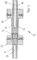
- the locking bolt 38 extends in a radial bore 40 of the cylinder head 34 and is in the direction of the piston rod section 14 by means of a helical spring 42.
- the closure for the track section for example the turnout closure, in the desired position, the pin 38 with its tapered End 41 engage in a corresponding receptacle 44 of the piston rod section 14.
- the cylinder 12 is immovably connected to the piston rod 13.
- an auxiliary piston assigned to the pin 38 must be used 46 acted upon with flowing through the bore 26 working fluid and after be pressed outside so that the bolt 38 with its inner end 41 in engagement arrives with the piston rod section 14.
- the auxiliary piston 46 simultaneously a connection 47 to the work space 22 opened or closed. This means, that when the locking pin 38 is in engagement with the piston portion 14 arrives, the auxiliary piston 46 releases the connection 47, so that via the channel 26 in the working space 22 can flow working fluid.
- the Cylinder 12 are shifted to the left. A corresponding arrangement can be found in the cylinder head 36 again.
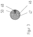
- FIG 3 also shows that the working space 22 with the bore 26 can be connected via a bore 50 which can be closed by a check valve 48, so that working fluid can flow back into the bore 26 when the cylinder 12 is again moved back into the position to be removed from FIGS. 2 and 4, and then to be locked.
- a double-acting Cylinder 52 includes, within which there is a stationary piston rod 54 extends so that the cylinder 52 moves along the piston rod 54.
- working fluid is arranged in a stationary manner via bearing eyes 76 of the bearing block 78 Piston rod 54 supplied.
- the auxiliary piston 56 is simultaneously from the bearing eye 76 through a bore 80 and one between the outer wall 82 of the piston rod of the auxiliary piston 56 and of sections 84, 86 of the Inner wall 88 of the piston rod 54 limited channel (indicated by the arrow 90)
- Working fluid directed into the longitudinal bore 92 of the piston rod 54 to be on this Way, the work space, not shown, between cylinder 52 and the like To apply section of the piston rod 54 and to move the cylinder 52.
- a corresponding locking arrangement is located on the opposite, stationary arranged end of the piston rod 54.
- FIG. 5 further clarifies that the legs 62, 64 are coaxial with their pivot axes can be supported on sections of the bearing block 78, so that the axles are relieved he follows.
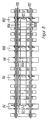
- a completely pre-assembled main part of the switch is shown in principle, in which the switch tongues 110, 112 are adjustable via adjusting devices, from which are shown purely in principle piston-cylinder arrangements 12, 52, which 1-7 correspond.
- the piston-cylinder arrangements 12, 52 are according to the invention for switches with ballast substructure in trough or lock compartment sleepers 94, 96, 100, 102 and are arranged by a common working fluid reservoir 104 supplied with working fluid via lines 106 and 108, which are preferably below the Rail should be arranged so as not to interfere with the tamping process.
- the Working fluid reservoir 104 itself is also in a trough or lock compartment threshold trained threshold 98 arranged.
Landscapes
- Engineering & Computer Science (AREA)
- Mechanical Engineering (AREA)
- Actuator (AREA)
- Oscillators With Electromechanical Resonators (AREA)
- Massaging Devices (AREA)
- Component Parts Of Construction Machinery (AREA)
Abstract
Description
- Fig. 1
- eine erste Ausführungsform einer Stelleinrichtung mit von dieser ausgehender und zu Klammerverschlüssen führenden Schieberstange,
- Fig. 2
- eine vergrößerte Darstellung der Stelleinrichtung gemäß Fig. 1,
- Fig. 3
- ein Ausschnitt der Stelleinrichtung nach Fig. 1 und 2,
- Fig. 4
- eine vergrößerte Darstellung der Stelleinrichtung nach Fig. 1 und 2 und im Ausschnitt,
- Fig. 5
- ein Ausschnitt einer zweiten Ausführungsform einer Stelleinrichtung,
- Fig. 6
- einen Ausschnitt der Stelleinrichtung nach Fig. 5 bei geöffnetem Arbeitsraum,
- Fig. 7
- einen der Fig. 6 entsprechenden Ausschnitt, jedoch bei verschlossenem Arbeitsraum und
- Fig. 8
- ein vormontiertes Weichengroßteil.
Claims (11)
- Stelleinrichtung (10) für zumindest einen zu verstellenden Gleisabschnitt, insbesondere Weichen- oder Herzstückspitzen-Stelleinrichtung, umfassend eine mit Arbeitsfluid beaufschlagbare Kolben-Zylinder-Anordnung (12, 13, 52, 54) mit von dieser ausgehendem und zu dem Gleisabschnitt führenden Verbindungselement wie Schieberstange, wobei die Stelleinrichtung einen doppelwirkenden Zylinder mit ortsfest angeordneter Kolbenstange umfasst, entlang der der mittelbar oder unmittelbar mit dem Verbindungselement (32) verbundene Zylinder verschiebbar und in seiner jeweiligen Endstellung arretierbar ist,
dadurch gekennzeichnet,dass die Kolbenstange (13) über zumindest ein sich im Zylinder (12) radial verschiebbares Element arretierbar ist, das über einen (ersten) Hilfskolben (44) in Ausgriff mit der Kolbenstange bringbar ist, und/oder dass der Zylinder (52) in seinem jeweiligen Endbereich eine außenseitige Aufnahme (72, 74) für ein Arretierelement (66, 62, 64, 68, 70) aufweist, das über ein innerhalb der Kolbenstange (52) sich erstreckenden fluidbeaufschlagbaren (zweiten) Hilfskolben (56) zum Arretieren oder Freigeben des Zylinders verstellbar ist. - Stelleinrichtung nach Anspruch 1,
dadurch gekennzeichnet,dass das vorzugsweise im Zylinderkopf (34, 36) radial verschiebbare Element ein federkraftbeaufschlagter Bolzen (38) ist. - Stelleinrichtung nach Anspruch 1 oder 2,
dadurch gekennzeichnet,dass vorzugsweise von den Stirnseiten der Kolbenstange (13, 54) jeweils ein von dem Arbeitsfluid durchströmbarer Kanal (26, 28, 92) ausgeht, der über eine von dem ersten oder einem weiteren in der Kolbenstange verschiebbaren Hilfskolben (44, 56) freiggeb- bzw. sperrbare Verbindung zu einem Arbeitsraum (22, 24) führt. - Stelleinrichtung nach zumindest einem der vorhergehenden Ansprüche,
dadurch gekennzeichnet,dass zwischen dem Arbeitsraum (22, 24) und dem Kanal wie axialer Bohrung (26, 28) in dem ortsfesten Kolben (13) ein Rückschlagventil (48) verläuft, welches bei fehlender Arbeitsfluidbeaufschlagung zum Verstellen des Zylinders (12, 52) geöffnet ist. - Stelleinrichtung nach zumindest einem der vorhergehenden Ansprüche,
dadurch gekennzeichnet,dass der Zylinder (12) an seinem jeweiligen Ende einen Zylinderkopf (34, 36) aufweist, in dem jeweils zwei diametral zueinander verlaufende verschiebbare die Kolbenstange arretierbare oder freigebene Elemente wie federkraftbeaufschlagte Bolzen (38) vorgesehen sind. - Stelleinrichtung nach zumindest einem der vorhergehenden Ansprüche,
dadurch gekennzeichnet,dass bei entarretiertem Zylinder (52) der zweite Hilfskolben (56) einen Fluidkanal (19) zwischen Arbeitsfluidzuführung einerseits und Zylinder (22) und der Kolbenstange (54) vorhandenem Arbeitsraum andererseits freigibt. - Stelleinrichtung nach zumindest einem der vorhergehenden Ansprüche,
dadurch gekennzeichnet,dass der zweite Hilfskolben (56) über ein stirnflächenseitig an der Kolbenstange (54) abgestütztes Federelement zum Verriegeln des Zylinders (52) kraftbeaufschlagt ist und dass zum Entriegeln des Zylinders der Hilfskolben (56) entgegen der Federkraft fluiddruckbeaufschlagt und in die Kolbenstange hineingezogen ist. - Stelleinrichtung nach zumindest einem der vorhergehenden Ansprüche,
dadurch gekennzeichnet,dass das Arretierelement (66) ein zwei in jeweils eine Aufnahme (72, 74) eingreifende Schenkel (62, 64) aufweisendes Klauenelement ist, das außenseitig an der Kolbenstange (54) bzw. einer Lagerung wie Lagerbock (78) abstützbar ist. - Anordnung zum Verstellen von auf Schwellen (94, 96, 98, 100, 102) abgestützten Gleisabschnitten wie insbesondere Weichenzungen mit mehreren die Gleisabschnitte verstellenden Verstelleinrichtungen (12, 52), von denen Schieberstangen ausgehen, die mit die Schienenabschnitte verstellenden und diese ver- bzw. entriegelnden Klammereinrichtungen verbunden sind, wobei jede Stelleinrichtung eine Zylinder-Kolben-Anordnung mit einem doppelwirkenden Zylinder umfasst, der entlang ortsfest angeordneter Kolbenstange verschiebbar ist und von dem eine zu der Klammereinrichtung führende Schieberstange ausgeht,
dadurch gekennzeichnet,dass jede Zylinder-Kolben-Anordnung jeweils in einer als Trogschwelle ausgebildeten Schwelle (94, 96, 100, 102) angeordnet ist, und dass die Zylinderkolbenanordnungen über einen gemeinsamen Arbeitsfluidspeicher (104) mit Arbeitsfluid versorgbar sind, wobei der Arbeitsfluidspeicher in einer weiteren als Trogschwelle (98) ausgebildeten Schwelle angeordnet ist. - Anordnung nach Anspruch 9,
dadurch gekennzeichnet,dass die Anordnung eine vormontierte transportierbare Einheit ist. - Stelleinrichtung nach Anspruch 10,
dadurch gekennzeichnet,dass das Verbindungselement wie Schieberstange (32) von dem Zylinder (12, 52) mittig ausgeht.
Applications Claiming Priority (2)
| Application Number | Priority Date | Filing Date | Title |
|---|---|---|---|
| DE19631174 | 1996-08-05 | ||
| DE19631174A DE19631174A1 (de) | 1996-08-05 | 1996-08-05 | Stelleinrichtung |
Publications (2)
| Publication Number | Publication Date |
|---|---|
| EP0824082A1 true EP0824082A1 (de) | 1998-02-18 |
| EP0824082B1 EP0824082B1 (de) | 2002-10-02 |
Family
ID=7801555
Family Applications (1)
| Application Number | Title | Priority Date | Filing Date |
|---|---|---|---|
| EP97113464A Expired - Lifetime EP0824082B1 (de) | 1996-08-05 | 1997-08-05 | Stelleinrichtung |
Country Status (4)
| Country | Link |
|---|---|
| EP (1) | EP0824082B1 (de) |
| AT (1) | ATE225269T1 (de) |
| DE (2) | DE19631174A1 (de) |
| ES (1) | ES2187705T3 (de) |
Cited By (1)
| Publication number | Priority date | Publication date | Assignee | Title |
|---|---|---|---|---|
| US8684318B2 (en) | 2010-09-16 | 2014-04-01 | Spx International Limited | Mechanical lock |
Citations (7)
| Publication number | Priority date | Publication date | Assignee | Title |
|---|---|---|---|---|
| DE2557574A1 (de) * | 1975-12-20 | 1977-06-30 | Fabeg Gmbh | Hydraulischer weichenantrieb |
| DE2744969A1 (de) * | 1977-10-06 | 1979-04-12 | Fabeg Gmbh | Hydraulischer weichenantrieb |
| DE3916696A1 (de) * | 1988-05-26 | 1989-12-07 | Barmag Barmer Maschf | Weichenantrieb mit linearantrieb |
| WO1992006244A1 (fr) * | 1990-09-28 | 1992-04-16 | Hsst Corporation | Dispositif pour encliqueter et fixer un corps anime d'un mouvement alternatif |
| EP0592755A1 (de) * | 1991-01-16 | 1994-04-20 | Alcatel Austria Aktiengesellschaft | Hydraulikeinheit |
| EP0601992A1 (de) * | 1992-11-04 | 1994-06-15 | Alcatel Austria Aktiengesellschaft | Weichenantrieb mit einem hydraulischen Stellzylinder |
| WO1996000160A1 (de) * | 1994-06-24 | 1996-01-04 | Vae Aktiengesellschaft | Einrichtung zum umstellen von weichen |
Family Cites Families (5)
| Publication number | Priority date | Publication date | Assignee | Title |
|---|---|---|---|---|
| DE1952823C3 (de) * | 1969-10-21 | 1975-08-21 | Standard Elektrik Lorenz Ag, 7000 Stuttgart | Einrichtung zum Umstellen von Schlankweichen in Eisenbahnanlagen |
| DE2144564A1 (de) * | 1971-09-06 | 1973-03-15 | Siemens Ag | Weichenstellsystem fuer eisenbahnanlagen mit schlankweichen |
| DE3106708C1 (de) * | 1981-02-23 | 1982-11-11 | Siemens AG, 1000 Berlin und 8000 München | Innenverschluß-Weichenantrieb |
| US4637579A (en) * | 1983-02-10 | 1987-01-20 | General Signal Corporation | Railroad switch mechanism |
| DE4332493C2 (de) * | 1993-09-24 | 2002-12-12 | Butzbacher Weichenbau Gmbh | Stelleinrichtung |
-
1996
- 1996-08-05 DE DE19631174A patent/DE19631174A1/de not_active Withdrawn
-
1997
- 1997-08-05 AT AT97113464T patent/ATE225269T1/de not_active IP Right Cessation
- 1997-08-05 ES ES97113464T patent/ES2187705T3/es not_active Expired - Lifetime
- 1997-08-05 DE DE59708361T patent/DE59708361D1/de not_active Expired - Fee Related
- 1997-08-05 EP EP97113464A patent/EP0824082B1/de not_active Expired - Lifetime
Patent Citations (7)
| Publication number | Priority date | Publication date | Assignee | Title |
|---|---|---|---|---|
| DE2557574A1 (de) * | 1975-12-20 | 1977-06-30 | Fabeg Gmbh | Hydraulischer weichenantrieb |
| DE2744969A1 (de) * | 1977-10-06 | 1979-04-12 | Fabeg Gmbh | Hydraulischer weichenantrieb |
| DE3916696A1 (de) * | 1988-05-26 | 1989-12-07 | Barmag Barmer Maschf | Weichenantrieb mit linearantrieb |
| WO1992006244A1 (fr) * | 1990-09-28 | 1992-04-16 | Hsst Corporation | Dispositif pour encliqueter et fixer un corps anime d'un mouvement alternatif |
| EP0592755A1 (de) * | 1991-01-16 | 1994-04-20 | Alcatel Austria Aktiengesellschaft | Hydraulikeinheit |
| EP0601992A1 (de) * | 1992-11-04 | 1994-06-15 | Alcatel Austria Aktiengesellschaft | Weichenantrieb mit einem hydraulischen Stellzylinder |
| WO1996000160A1 (de) * | 1994-06-24 | 1996-01-04 | Vae Aktiengesellschaft | Einrichtung zum umstellen von weichen |
Cited By (1)
| Publication number | Priority date | Publication date | Assignee | Title |
|---|---|---|---|---|
| US8684318B2 (en) | 2010-09-16 | 2014-04-01 | Spx International Limited | Mechanical lock |
Also Published As
| Publication number | Publication date |
|---|---|
| EP0824082B1 (de) | 2002-10-02 |
| DE19631174A1 (de) | 1998-02-12 |
| DE59708361D1 (de) | 2002-11-07 |
| ES2187705T3 (es) | 2003-06-16 |
| ATE225269T1 (de) | 2002-10-15 |
Similar Documents
| Publication | Publication Date | Title |
|---|---|---|
| DE69121506T3 (de) | Betätigungsvorrichtung für Eisenbahnweichen, insbesondere für Hochgeschwindigkeitsbahnen | |
| DE1950721A1 (de) | Werkstueckspanner | |
| DE19502105C5 (de) | Verschlußvorrichtung für Weichenzungen | |
| EP0684174B1 (de) | Einrichtung zum Verriegeln von beweglichen Weichenteilen | |
| EP0603156A1 (de) | Einrichtung zum Verriegeln von beweglichen Weichenteilen | |
| DE2817782C3 (de) | Zungenweiche | |
| DE2801249A1 (de) | Vorrichtung zum entgraten beim widerstandsstumpfschweissen von schienen | |
| EP0802102B1 (de) | Weichenendverschluss | |
| DE3020788C2 (de) | Innenverschlußeinrichtung für einen Weichenantrieb | |
| DE3543403C2 (de) | ||
| EP0824082B1 (de) | Stelleinrichtung | |
| EP0896915B1 (de) | Stelleinrichtung | |
| EP0779197B1 (de) | Einrichtung zum Sichern der Endlagen von Weichen- und Kreuzungsstellantrieben | |
| DE2744969A1 (de) | Hydraulischer weichenantrieb | |
| DE2450802A1 (de) | Klammerspitzenverschluss | |
| DE60132813T2 (de) | Betaetigungsanordnung | |
| EP1678024B1 (de) | Einrichtung zum verriegeln von beweglichen weichenteilen, insbesondere weichenverschluss | |
| DE4213288C2 (de) | Hydraulische Druck- und Zugvorrichtung, insbesondere für Eisenbahnschienen | |
| DE19606793C1 (de) | Vorrichtung zur Lenksinnumkehr bei Kettenfahrzeugen | |
| DE2836243A1 (de) | Betaetigungs- und spannzylinder | |
| DE4016632A1 (de) | Betaetigungszylinder, insbesondere doppelt wirkender tuerschliesszylinder fuer schienenfahrzeuge | |
| EP0601992A1 (de) | Weichenantrieb mit einem hydraulischen Stellzylinder | |
| DE102005032390A1 (de) | Mehrfach-Hubgerüst mit Verriegelungsmitteln zur Sicherung der Bewegungsreihenfolge der ausfahrbaren Hubmasten | |
| DE102005014214A1 (de) | Schieber, insbesondere Doppelplattenschieber | |
| EP1110841A1 (de) | Schieberstange |
Legal Events
| Date | Code | Title | Description |
|---|---|---|---|
| PUAI | Public reference made under article 153(3) epc to a published international application that has entered the european phase |
Free format text: ORIGINAL CODE: 0009012 |
|
| AK | Designated contracting states |
Kind code of ref document: A1 Designated state(s): AT BE DE ES FR GB IT LU SE |
|
| AX | Request for extension of the european patent |
Free format text: AL;LT;LV;RO;SI |
|
| 17P | Request for examination filed |
Effective date: 19980330 |
|
| AKX | Designation fees paid |
Free format text: AT BE DE ES FR GB IT LU SE |
|
| RBV | Designated contracting states (corrected) |
Designated state(s): AT BE DE ES FR GB IT LU SE |
|
| RAP1 | Party data changed (applicant data changed or rights of an application transferred) |
Owner name: BWG BUTZBACHER WEICHENBAU GESELLSCHAFT MBH & CO. K |
|
| 17Q | First examination report despatched |
Effective date: 20010215 |
|
| RAP1 | Party data changed (applicant data changed or rights of an application transferred) |
Owner name: BWG GMBH & CO. KG |
|
| GRAG | Despatch of communication of intention to grant |
Free format text: ORIGINAL CODE: EPIDOS AGRA |
|
| GRAG | Despatch of communication of intention to grant |
Free format text: ORIGINAL CODE: EPIDOS AGRA |
|
| GRAG | Despatch of communication of intention to grant |
Free format text: ORIGINAL CODE: EPIDOS AGRA |
|
| GRAH | Despatch of communication of intention to grant a patent |
Free format text: ORIGINAL CODE: EPIDOS IGRA |
|
| GRAH | Despatch of communication of intention to grant a patent |
Free format text: ORIGINAL CODE: EPIDOS IGRA |
|
| GRAA | (expected) grant |
Free format text: ORIGINAL CODE: 0009210 |
|
| AK | Designated contracting states |
Kind code of ref document: B1 Designated state(s): AT BE DE ES FR GB IT LU SE |
|
| REF | Corresponds to: |
Ref document number: 225269 Country of ref document: AT Date of ref document: 20021015 Kind code of ref document: T |
|
| REG | Reference to a national code |
Ref country code: GB Ref legal event code: FG4D Free format text: NOT ENGLISH |
|
| REF | Corresponds to: |
Ref document number: 59708361 Country of ref document: DE Date of ref document: 20021107 |
|
| RAP2 | Party data changed (patent owner data changed or rights of a patent transferred) |
Owner name: VAE AKTIENGESELLSCHAFT Owner name: BWG GMBH & CO. KG |
|
| GBT | Gb: translation of ep patent filed (gb section 77(6)(a)/1977) |
Effective date: 20030129 |
|
| ET | Fr: translation filed | ||
| REG | Reference to a national code |
Ref country code: ES Ref legal event code: FG2A Ref document number: 2187705 Country of ref document: ES Kind code of ref document: T3 |
|
| PLBE | No opposition filed within time limit |
Free format text: ORIGINAL CODE: 0009261 |
|
| STAA | Information on the status of an ep patent application or granted ep patent |
Free format text: STATUS: NO OPPOSITION FILED WITHIN TIME LIMIT |
|
| 26N | No opposition filed |
Effective date: 20030703 |
|
| PGFP | Annual fee paid to national office [announced via postgrant information from national office to epo] |
Ref country code: GB Payment date: 20050725 Year of fee payment: 9 |
|
| PGFP | Annual fee paid to national office [announced via postgrant information from national office to epo] |
Ref country code: SE Payment date: 20050811 Year of fee payment: 9 |
|
| PGFP | Annual fee paid to national office [announced via postgrant information from national office to epo] |
Ref country code: FR Payment date: 20050812 Year of fee payment: 9 Ref country code: DE Payment date: 20050812 Year of fee payment: 9 |
|
| PGFP | Annual fee paid to national office [announced via postgrant information from national office to epo] |
Ref country code: ES Payment date: 20050816 Year of fee payment: 9 Ref country code: AT Payment date: 20050816 Year of fee payment: 9 |
|
| PGFP | Annual fee paid to national office [announced via postgrant information from national office to epo] |
Ref country code: LU Payment date: 20050822 Year of fee payment: 9 |
|
| PGFP | Annual fee paid to national office [announced via postgrant information from national office to epo] |
Ref country code: BE Payment date: 20050914 Year of fee payment: 9 |
|
| PG25 | Lapsed in a contracting state [announced via postgrant information from national office to epo] |
Ref country code: AT Free format text: LAPSE BECAUSE OF NON-PAYMENT OF DUE FEES Effective date: 20060805 |
|
| PG25 | Lapsed in a contracting state [announced via postgrant information from national office to epo] |
Ref country code: SE Free format text: LAPSE BECAUSE OF NON-PAYMENT OF DUE FEES Effective date: 20060806 |
|
| PG25 | Lapsed in a contracting state [announced via postgrant information from national office to epo] |
Ref country code: BE Free format text: LAPSE BECAUSE OF NON-PAYMENT OF DUE FEES Effective date: 20060831 |
|
| PGFP | Annual fee paid to national office [announced via postgrant information from national office to epo] |
Ref country code: IT Payment date: 20060831 Year of fee payment: 10 |
|
| PG25 | Lapsed in a contracting state [announced via postgrant information from national office to epo] |
Ref country code: DE Free format text: LAPSE BECAUSE OF NON-PAYMENT OF DUE FEES Effective date: 20070301 |
|
| EUG | Se: european patent has lapsed | ||
| GBPC | Gb: european patent ceased through non-payment of renewal fee |
Effective date: 20060805 |
|
| REG | Reference to a national code |
Ref country code: FR Ref legal event code: ST Effective date: 20070430 |
|
| REG | Reference to a national code |
Ref country code: ES Ref legal event code: FD2A Effective date: 20060807 |
|
| PG25 | Lapsed in a contracting state [announced via postgrant information from national office to epo] |
Ref country code: GB Free format text: LAPSE BECAUSE OF NON-PAYMENT OF DUE FEES Effective date: 20060805 |
|
| BERE | Be: lapsed |
Owner name: *VAE A.G. Effective date: 20060831 Owner name: *BWG G.M.B.H. & CO. K.G. Effective date: 20060831 |
|
| PG25 | Lapsed in a contracting state [announced via postgrant information from national office to epo] |
Ref country code: ES Free format text: LAPSE BECAUSE OF NON-PAYMENT OF DUE FEES Effective date: 20060807 |
|
| PG25 | Lapsed in a contracting state [announced via postgrant information from national office to epo] |
Ref country code: FR Free format text: LAPSE BECAUSE OF NON-PAYMENT OF DUE FEES Effective date: 20060831 |
|
| PG25 | Lapsed in a contracting state [announced via postgrant information from national office to epo] |
Ref country code: LU Free format text: LAPSE BECAUSE OF NON-PAYMENT OF DUE FEES Effective date: 20060805 |
|
| PG25 | Lapsed in a contracting state [announced via postgrant information from national office to epo] |
Ref country code: IT Free format text: LAPSE BECAUSE OF NON-PAYMENT OF DUE FEES Effective date: 20070805 |