EP0824175A2 - Verrou - Google Patents
Verrou Download PDFInfo
- Publication number
- EP0824175A2 EP0824175A2 EP97306055A EP97306055A EP0824175A2 EP 0824175 A2 EP0824175 A2 EP 0824175A2 EP 97306055 A EP97306055 A EP 97306055A EP 97306055 A EP97306055 A EP 97306055A EP 0824175 A2 EP0824175 A2 EP 0824175A2
- Authority
- EP
- European Patent Office
- Prior art keywords
- bolt
- catch
- gate
- movement
- force
- Prior art date
- Legal status (The legal status is an assumption and is not a legal conclusion. Google has not performed a legal analysis and makes no representation as to the accuracy of the status listed.)
- Withdrawn
Links
Images

Classifications
-
- E—FIXED CONSTRUCTIONS
- E05—LOCKS; KEYS; WINDOW OR DOOR FITTINGS; SAFES
- E05B—LOCKS; ACCESSORIES THEREFOR; HANDCUFFS
- E05B65/00—Locks or fastenings for special use
- E05B65/0014—Locks or fastenings for special use to prevent opening by children
-
- E—FIXED CONSTRUCTIONS
- E05—LOCKS; KEYS; WINDOW OR DOOR FITTINGS; SAFES
- E05C—BOLTS OR FASTENING DEVICES FOR WINGS, SPECIALLY FOR DOORS OR WINDOWS
- E05C1/00—Fastening devices with bolts moving rectilinearly
- E05C1/02—Fastening devices with bolts moving rectilinearly without latching action
- E05C1/06—Fastening devices with bolts moving rectilinearly without latching action with operating handle or equivalent member moving otherwise than rigidly with the bolt
-
- E—FIXED CONSTRUCTIONS
- E06—DOORS, WINDOWS, SHUTTERS, OR ROLLER BLINDS IN GENERAL; LADDERS
- E06B—FIXED OR MOVABLE CLOSURES FOR OPENINGS IN BUILDINGS, VEHICLES, FENCES OR LIKE ENCLOSURES IN GENERAL, e.g. DOORS, WINDOWS, BLINDS, GATES
- E06B9/00—Screening or protective devices for wall or similar openings, with or without operating or securing mechanisms; Closures of similar construction
- E06B9/02—Shutters, movable grilles, or other safety closing devices, e.g. against burglary
-
- E—FIXED CONSTRUCTIONS
- E06—DOORS, WINDOWS, SHUTTERS, OR ROLLER BLINDS IN GENERAL; LADDERS
- E06B—FIXED OR MOVABLE CLOSURES FOR OPENINGS IN BUILDINGS, VEHICLES, FENCES OR LIKE ENCLOSURES IN GENERAL, e.g. DOORS, WINDOWS, BLINDS, GATES
- E06B9/00—Screening or protective devices for wall or similar openings, with or without operating or securing mechanisms; Closures of similar construction
- E06B2009/002—Safety guards or gates
Definitions
- This invention relates to a catch, and particularly to a catch for use with child safety gates.
- a catch for a gate comprising a bolt which is moveable between a locked position in which it can engage a member to resist movement of the gate and a free position in which it can be disengaged from said member, and an actuator which can move the bolt between the free and locked positions, such that a given movement of the actuator produces variable extents of movement of the bolt.
- the bolt moves more when at or adjacent its free position than when adjacent its locked position.
- the force with which the bolt moves is less when at or adjacent its free position than when adjacent its locked position.
- the bolt moves in an axial manner, optionally along the top bar of the gate.
- the catch also comprises locking means to lock the bolt in the locked position, for example by maintaining the force of the actuator against the bolt.
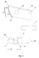
- a catch is mounted on a top bar 1 of a gate (not shown).
- the catch comprises a bolt 10, one end of which 10a is hollow and receives a portion of the bar 1 so that the bolt 10 is slidable axially along the bar 1.
- Flaps 11 (only one shown) are attached at each lateral side of the bolt 10 at its opposite end 10b and extend a few millimetres from the end 10b of the bolt 10. In use, flaps 11 engage an upright member of the gate frame (not shown) so as to lock the gate in position.
- a pair of hemispherical or spherical buttons 12 protrude in opposite directions from opposite lateral sides of the bolt 10.
- Each button 12 is movable in a lateral direction with respect to the bolt 10 under the force of a spring (not shown) such that in the absence of any force pushing them together, the buttons are forced outwards from the lateral sides of the bolt 10.
- the buttons 12 are maintained within the bolt 10 by a U-shaped collar 13 on each lateral side of the bolt 10.
- a handle 20 is generally U-shaped in end view and has apertures 28 in the lateral sides. Handle 20 is pivotally mounted on bar 1 at pivot point 21, although a separate embodiment of the invention might allow the handle 20 to move in a sliding manner (e.g. orthogonally) with respect to the bar 1.
- the handle 20 has a profiled edge 22 which is inclined from a lower edge 23 at a constant angle along a first portion 24 and is curved along a second portion 25.
- the curved section 25 has a variable radius.
- the profiled edge 22 could equally comprise two (or more) portions inclined at constant (but mutually different) angles, or a curved section adjacent the lower edge with a straight section adjacent the upper edge 26.
- the end 22 could be formed as a curve from lower edge 23 to upper edge 26. Such a curve could have a constant radius, or a radius which changes (eg decreases) from the lower edge 23 to the upper edge 26.
- the bolt 10 is located on the bar 1 and attached thereto by the spring (not shown).
- the handle 20 is attached to the bar 1 at pivot point 21, and downward pivotal movement of the handle 20 engages the edge 22 against the flaps 11 at portion 24. Further downward pivotal movement of the handle 20 forces the end portion 24 to slide past the flaps 11, thereby forcing the bolt 10 to move axially against the spring tension in the direction B shown in the drawings and moving the flaps 11 towards the upright member of the frame (not shown). Movement of the bolt in response to a constant rate of downward movement of the handle 20 continues at a constant (high) rate and with (minimal) force provided that the portion 24 is inclined at a constant angle.
- the bolt 10 will be moved by a relatively smaller amount and with greater force.
- a smooth transition curve on edge 22 will produce a rate of movement of the bolt 10 which gradually decreases as the force with which the bolt 10 moves increases.
- the buttons 12 protrude from the U-shaped collar 13 through the holes 28 in the handle 20 and are held in that position by the spring (not shown), thereby preventing further movement of the handle 20 and retraction of the bolt 10 by the spring tension.
- the handle 20 is pushed to its parallel position, the bolt 10 is locked against the upright member (not shown).
- the buttons 12 can be depressed simultaneously against the force of the spring(s) not shown, so that the handle 20 can be raised and the bolt 10 can be retracted by the spring (not shown).
- the profile of the edge 22 of the handle 20 can be adjusted to provide maximum force transmission to the axial movement of the bolt 10 at later stages of engagement with the upright member to which the gate is locked in use.
- Fig 4 shows the position in which maximum force is applied.
- the profile can be adjusted to allow maximum movement of the bolt with minimum force transmission in the early stages of engagement (such as the stage seen in Fig 3 in this example) when the bolt is required to close up large gaps between the upright member and the gate, but is not required to exert extreme force on the upright member.
- the bolt can be locked in position at its point of maximum force transmission.
Landscapes
- Engineering & Computer Science (AREA)
- Structural Engineering (AREA)
- Mechanical Engineering (AREA)
- Architecture (AREA)
- Civil Engineering (AREA)
- Gates (AREA)
Applications Claiming Priority (2)
| Application Number | Priority Date | Filing Date | Title |
|---|---|---|---|
| GBGB9616786.1A GB9616786D0 (en) | 1996-08-09 | 1996-08-09 | Catch |
| GB9616786 | 1996-08-09 |
Publications (2)
| Publication Number | Publication Date |
|---|---|
| EP0824175A2 true EP0824175A2 (fr) | 1998-02-18 |
| EP0824175A3 EP0824175A3 (fr) | 1999-07-07 |
Family
ID=10798285
Family Applications (1)
| Application Number | Title | Priority Date | Filing Date |
|---|---|---|---|
| EP97306055A Withdrawn EP0824175A3 (fr) | 1996-08-09 | 1997-08-08 | Verrou |
Country Status (2)
| Country | Link |
|---|---|
| EP (1) | EP0824175A3 (fr) |
| GB (1) | GB9616786D0 (fr) |
Cited By (2)
| Publication number | Priority date | Publication date | Assignee | Title |
|---|---|---|---|---|
| ES2161102A1 (es) * | 1998-03-05 | 2001-11-16 | Cruzado Manuel Lomena | Puerta abatible para valla. |
| FR2877980A1 (fr) * | 2004-11-15 | 2006-05-19 | Thierache Au Creuset | Dispositif de verrouillage pour portillon d'acces a une zone securisee notamment une piscine |
Family Cites Families (6)
| Publication number | Priority date | Publication date | Assignee | Title |
|---|---|---|---|---|
| US2588356A (en) * | 1950-02-13 | 1952-03-11 | Charles L Burgoyne | Closure fastener |
| FR1441373A (fr) * | 1965-07-31 | 1966-06-03 | Grille de protection à monter dans un encadrement de porte ou analogue | |
| GB2180586B (en) * | 1985-09-13 | 1988-12-14 | Hardware & Systems Patents Ltd | Security device |
| GB2187495B (en) * | 1986-01-17 | 1989-11-01 | Hago Prod Ltd | Safety barrier |
| GB8614662D0 (en) * | 1986-06-17 | 1986-07-23 | Boots Co Plc | Safety barrier assembly |
| US5396732A (en) * | 1993-03-29 | 1995-03-14 | Andersen; Finn | Safety barrier |
-
1996
- 1996-08-09 GB GBGB9616786.1A patent/GB9616786D0/en active Pending
-
1997
- 1997-08-08 EP EP97306055A patent/EP0824175A3/fr not_active Withdrawn
Cited By (2)
| Publication number | Priority date | Publication date | Assignee | Title |
|---|---|---|---|---|
| ES2161102A1 (es) * | 1998-03-05 | 2001-11-16 | Cruzado Manuel Lomena | Puerta abatible para valla. |
| FR2877980A1 (fr) * | 2004-11-15 | 2006-05-19 | Thierache Au Creuset | Dispositif de verrouillage pour portillon d'acces a une zone securisee notamment une piscine |
Also Published As
| Publication number | Publication date |
|---|---|
| GB9616786D0 (en) | 1996-09-25 |
| EP0824175A3 (fr) | 1999-07-07 |
Similar Documents
| Publication | Publication Date | Title |
|---|---|---|
| CA2310436C (fr) | Fenetre combinant coulissement et pivotement | |
| CN108291414B (zh) | 具有锁式致动的连接机构的门或其他可关闭的板体 | |
| US6112461A (en) | Safety gate for children | |
| US8182002B2 (en) | Multipoint door lock system with header and sill lock pins | |
| AU2003278645B2 (en) | A self-latching device | |
| EP3423652B1 (fr) | Agencement de verrou ayant une poignée | |
| US6120071A (en) | Mortise latch vertical rod exit device | |
| US20150027060A1 (en) | Hands-Free Safety Gate | |
| KR101641021B1 (ko) | 창호 잠금장치 | |
| US4562667A (en) | Panel closure assembly for window, door or the like | |
| WO2018132856A1 (fr) | Dispositif de verrouillage et porte coulissante à dispositif de verrouillage | |
| CA2337989C (fr) | Element coulissant | |
| DE69811750T2 (de) | Verriegelungsbeschlag für Schiebetür, Schiebefenster oder ähnliches | |
| EP1954908B1 (fr) | Ensembles barrière de sécurité pour enfants | |
| EP0824175A2 (fr) | Verrou | |
| US5752727A (en) | Drive-rod type drive mechanism | |
| US20070001469A1 (en) | Retractable strike for panic locks | |
| TWI617729B (zh) | 門窗 | |
| EP1911915B1 (fr) | Tige de verrouillage à frottement | |
| JPH11506507A (ja) | リストリクタ装置 | |
| EP1612358B1 (fr) | Coordinateur de fermeture de portes à double battants | |
| JP3987996B2 (ja) | 引き戸のローラーラッチ機構 | |
| GB2379952A (en) | Automatic catch for a door or window | |
| JP2668674B2 (ja) | 子扉錠 | |
| JP3169743B2 (ja) | 用心錠 |
Legal Events
| Date | Code | Title | Description |
|---|---|---|---|
| PUAI | Public reference made under article 153(3) epc to a published international application that has entered the european phase |
Free format text: ORIGINAL CODE: 0009012 |
|
| AK | Designated contracting states |
Kind code of ref document: A2 Designated state(s): AT BE CH DE DK ES FI FR GB GR IE IT LI LU MC NL PT SE |
|
| AX | Request for extension of the european patent |
Free format text: AL;LT;LV;RO;SI |
|
| RAP1 | Party data changed (applicant data changed or rights of an application transferred) |
Owner name: BELDRAY LIMITED |
|
| PUAL | Search report despatched |
Free format text: ORIGINAL CODE: 0009013 |
|
| AK | Designated contracting states |
Kind code of ref document: A3 Designated state(s): AT BE CH DE DK ES FI FR GB GR IE IT LI LU MC NL PT SE |
|
| AX | Request for extension of the european patent |
Free format text: AL;LT;LV;RO;SI |
|
| AKX | Designation fees paid | ||
| REG | Reference to a national code |
Ref country code: DE Ref legal event code: 8566 |
|
| STAA | Information on the status of an ep patent application or granted ep patent |
Free format text: STATUS: THE APPLICATION IS DEEMED TO BE WITHDRAWN |
|
| 18D | Application deemed to be withdrawn |
Effective date: 20000108 |