EP0824191B1 - Compresseur à déplacement variable - Google Patents
Compresseur à déplacement variable Download PDFInfo
- Publication number
- EP0824191B1 EP0824191B1 EP97113875A EP97113875A EP0824191B1 EP 0824191 B1 EP0824191 B1 EP 0824191B1 EP 97113875 A EP97113875 A EP 97113875A EP 97113875 A EP97113875 A EP 97113875A EP 0824191 B1 EP0824191 B1 EP 0824191B1
- Authority
- EP
- European Patent Office
- Prior art keywords
- drive shaft
- swash plate
- central bore
- shutoff member
- bore
- Prior art date
- Legal status (The legal status is an assumption and is not a legal conclusion. Google has not performed a legal analysis and makes no representation as to the accuracy of the status listed.)
- Expired - Lifetime
Links
- 238000006073 displacement reaction Methods 0.000 title claims description 47
- 239000012530 fluid Substances 0.000 claims description 12
- 238000004378 air conditioning Methods 0.000 claims description 11
- 239000003507 refrigerant Substances 0.000 description 39
- 238000001816 cooling Methods 0.000 description 13
- 230000002093 peripheral effect Effects 0.000 description 11
- 230000000740 bleeding effect Effects 0.000 description 7
- XEEYBQQBJWHFJM-UHFFFAOYSA-N Iron Chemical group [Fe] XEEYBQQBJWHFJM-UHFFFAOYSA-N 0.000 description 6
- 230000003247 decreasing effect Effects 0.000 description 6
- 230000007423 decrease Effects 0.000 description 5
- 238000004891 communication Methods 0.000 description 4
- 230000006835 compression Effects 0.000 description 4
- 238000007906 compression Methods 0.000 description 4
- 238000012544 monitoring process Methods 0.000 description 2
- 230000003134 recirculating effect Effects 0.000 description 2
- 230000035939 shock Effects 0.000 description 2
- 230000004323 axial length Effects 0.000 description 1
- 238000006243 chemical reaction Methods 0.000 description 1
- 230000001419 dependent effect Effects 0.000 description 1
- 238000011161 development Methods 0.000 description 1
- 230000018109 developmental process Effects 0.000 description 1
- 239000010687 lubricating oil Substances 0.000 description 1
- 238000005461 lubrication Methods 0.000 description 1
- 238000003754 machining Methods 0.000 description 1
- 239000003921 oil Substances 0.000 description 1
- 230000000717 retained effect Effects 0.000 description 1
Images


Classifications
-
- F—MECHANICAL ENGINEERING; LIGHTING; HEATING; WEAPONS; BLASTING
- F04—POSITIVE - DISPLACEMENT MACHINES FOR LIQUIDS; PUMPS FOR LIQUIDS OR ELASTIC FLUIDS
- F04B—POSITIVE-DISPLACEMENT MACHINES FOR LIQUIDS; PUMPS
- F04B27/00—Multi-cylinder pumps specially adapted for elastic fluids and characterised by number or arrangement of cylinders
- F04B27/08—Multi-cylinder pumps specially adapted for elastic fluids and characterised by number or arrangement of cylinders having cylinders coaxial with, or parallel or inclined to, main shaft axis
- F04B27/14—Control
- F04B27/16—Control of pumps with stationary cylinders
- F04B27/18—Control of pumps with stationary cylinders by varying the relative positions of a swash plate and a cylinder block
- F04B27/1804—Controlled by crankcase pressure
-
- F—MECHANICAL ENGINEERING; LIGHTING; HEATING; WEAPONS; BLASTING
- F04—POSITIVE - DISPLACEMENT MACHINES FOR LIQUIDS; PUMPS FOR LIQUIDS OR ELASTIC FLUIDS
- F04B—POSITIVE-DISPLACEMENT MACHINES FOR LIQUIDS; PUMPS
- F04B27/00—Multi-cylinder pumps specially adapted for elastic fluids and characterised by number or arrangement of cylinders
- F04B27/08—Multi-cylinder pumps specially adapted for elastic fluids and characterised by number or arrangement of cylinders having cylinders coaxial with, or parallel or inclined to, main shaft axis
- F04B27/10—Multi-cylinder pumps specially adapted for elastic fluids and characterised by number or arrangement of cylinders having cylinders coaxial with, or parallel or inclined to, main shaft axis having stationary cylinders
- F04B27/1036—Component parts, details, e.g. sealings, lubrication
- F04B27/1054—Actuating elements
- F04B27/1063—Actuating-element bearing means or driving-axis bearing means
-
- F—MECHANICAL ENGINEERING; LIGHTING; HEATING; WEAPONS; BLASTING
- F04—POSITIVE - DISPLACEMENT MACHINES FOR LIQUIDS; PUMPS FOR LIQUIDS OR ELASTIC FLUIDS
- F04B—POSITIVE-DISPLACEMENT MACHINES FOR LIQUIDS; PUMPS
- F04B49/00—Control, e.g. of pump delivery, or pump pressure of, or safety measures for, machines, pumps, or pumping installations, not otherwise provided for, or of interest apart from, groups F04B1/00 - F04B47/00
- F04B49/22—Control, e.g. of pump delivery, or pump pressure of, or safety measures for, machines, pumps, or pumping installations, not otherwise provided for, or of interest apart from, groups F04B1/00 - F04B47/00 by means of valves
- F04B49/225—Control, e.g. of pump delivery, or pump pressure of, or safety measures for, machines, pumps, or pumping installations, not otherwise provided for, or of interest apart from, groups F04B1/00 - F04B47/00 by means of valves with throttling valves or valves varying the pump inlet opening or the outlet opening
Definitions
- the present invention relates to a variable displacement compressor according to the preamble of claim 1, which is adapted for use in an automotive air conditioning system that lacks a clutch between the compressor and the automotive engine. More specifically, the invention relates to a variable displacement compressor of the type that shuts off the flow of refrigerant gas to the suction chamber while the compressor is in its minimum displacement state by using a shutoff member, which is located in a central bore formed in the cylinder block.
- variable displacement refrigerant compressor of the same type as that of the present invention will be explained.
- the compressor comprises a housing defining therein a crankcase, a suction chamber receiving refrigerant gas before compression and a discharge chamber receiving refrigerant gas after compression.
- the housing includes a cylinder block having a front end surface exposed to the crankcase and including a plurality of cylinder bores each receiving therein a working piston.
- the compressor further comprises a drive shaft rotatably supported in the crankcase, a swash plate supported on the drive shaft to rotate therewith and to tilt with respect to the axis of the drive shaft between minimum and maximum tilt angle positions while moving along the drive shaft, thereby making a wobbling movement at a variable tilt angle.
- Each piston is slidably received in one of the cylinder bores and is operatively connected to the swash plate such that the wobbling movement of the swash plate at the variable tilt angle is converted into reciprocal movement of the pistons, and the stroke of the pistons in the associated cylinder bores varies accordingly.
- the housing further includes a suction passage receiving an inflow of refrigerant gas from an air conditioning system, to which the compressor is connected. The suction passage is communicable with the suction chamber.
- the compressor further includes a shutoff means in the form of a cup-shaped spool slidably fitted in the above central bore for shutting off fluid communication between the suction passage and the suction chamber to stop the inflow of refrigerant gas into the cylinder bores when the swash plate is brought to its minimum displacement location.
- the rear end of the drive shaft is inserted into the shutoff spool and is supported by a radial bearing mounted on the drive shaft within the shutoff spool.
- the compressor further includes a displacement control valve for controlling the tilt angle of the swash plate in response to a change in the cooling demand or load.
- the swash plate tilts in response to the difference between the pressure in the crankcase and the pressure in the cylinder bores.
- the swash plate is brought to the minimum tilt angle position, and the shutoff spool is moved in the central bore to close the suction passage so the flow of refrigerant gas into the suction chamber is shut off.
- the refrigerant gas within the compressor is circulated through the discharge chamber, the crankcase, the suction chamber and the cylinder bores and, simultaneously, lubrication oil contained in and entrained by the refrigerant gas lubricates the internal parts of the compressor.
- compressors of this type there has been no disclosure with reference to the arrangement of the radial bearing relative to the central bore of the cylinder block.
- the radial bearing may slide to such an extent that the center of that radial bearing, as defined by an imaginary plane extending perpendicularly to the drive shaft axis and passing through the axial midpoint of the bearing, will come out of the central bore, or move beyond the front end surface of the cylinder block, while the swash plate is being moved toward its maximum tilt angle position.
- shutoff member would tend to incline within the central bore with respect to the axis of the drive shaft and become misaligned with the axis of the drive shaft.
- the shutoff member may fail to completely shut off the suction passage so that some of the refrigerant gas in the suction passage may flow into the suction chamber. This would result in performance of the cooling operation even when there is no demand for cooling.
- DE-A-44 39 512, DE-A-44 46 832, DE-A-195 14 376 and DE-A-195 17 334 show further variable displacement compressors.
- a generic variable displacement compressor is known from EP-A-0 716 228.
- a housing defines a crankcase.
- the housing includes a cylinder block, which has a cylinder bore and a central bore.
- the central bore has a cylindrical surface.
- the cylinder bore and the central bore have parallel axes.
- the axis of the cylinder bore is spaced radially from the axis of the central bore.
- the cylinder block has a front wall.
- the front wall extends radially from a front opening of the central bore to the cylinder bore and is substantially perpendicular to the axis of the central bore.
- a drive shaft is supported by the housing.
- the drive shaft has a front end and a rear end.
- a mid-portion of the drive shaft is located in the crankcase and the rear end of the drive shaft is located in and coaxial to the central bore.
- a swash plate is supported on the drive shaft.
- the swash plate is pivotally supported to rotate integrally with the drive shaft and to incline with respect to a plane perpendicular to the axis of the drive shaft between a maximum inclination and a minimum inclination.
- the swash plate moves generally in the axial direction of the drive shaft when the inclination changes.
- a piston located in the cylinder bore. The piston is connected to the swash plate such that rotation of the swash plate is converted to reciprocal movement of the piston and the stroke of the piston is determined by the inclination of the swash plate.
- a fluid passage has an inlet and an outlet.
- a hollow, cylindrical shutoff member is located in the central bore between the drive shaft and the cylindrical surface to shut the fluid passage.
- the shutoff member has an inner surface.
- the shutoff member moves axially along the central bore when the inclination of the swash plate changes such that, when the inclination of the swash plate increases, the shutoff member follows the swash plate toward the front end of the drive shaft and a front section of the shutoff member loses contact with the cylindrical surface of the central bore.
- the shutoff member has a radial load bearing area on its inner surface for bearing radial loads applied between the drive shaft and the shutoff member.
- the front end of the central bore remains on the front side of a plane perpendicular to the axis of the drive shaft that bisects the load bearing area, regardless of the axial position of the shutoff member.
- An object of the invention is to further develop a variable displacement compressor according to the preamble of claim 1 such that the shutoff member is prevented from being inclined in the central bore of the cylinder block.
- variable displacement compressor having the features of claim 1.
- the compressor permits the shutoff member to completely close the suction passage when the swash plate is moved to its minimum displacement position.
- variable displacement refrigerant compressor of the invention will describe a preferred embodiment of a variable displacement refrigerant compressor of the invention with reference to FIGS. 1 to 5.
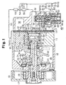
- the compressor includes a housing assembly including a cylinder block 11, a front housing 12, which is clamped to the front end of the cylinder block, and a rear housing 13, which is secured to the rear end of the cylinder block 11, and a valve plate 14 is located between the rear housing and the cylinder block 11.
- the front housing 12 cooperates with the cylinder block 11 to define a crankcase 15.
- Located in the crankcase 15 is a drive shaft 16 rotatably supported at its front end by the front housing 12 and at the opposite end by the cylinder block 11 by way of a radial bearing 30 and a shutoff spool, or shutoff member 28, which has the form of a cup.
- the radial bearing 30 and the shutoff member 28 will be described in detail below.
- the front end of the drive shaft 16 extends out of the crankcase 15, and a pulley 17 is fastened to the front end surface of the drive shaft.
- the pulley 17 is rotatably supported on a front extension of the front housing 12 by way of an angular bearing 19, which carries both axial and radial loads applied to the pulley 17.
- the pulley 17 is operatively connected to an engine of a vehicle (not shown) with no intervening clutch.
- a belt 18 engages the pulley 17.
- a lip seal 20 is provided between the drive shaft 16 and the front housing 12 to seal the crankcase 15.
- a lug plate or a rotor 21 is fixed on the drive shaft 16 for rotation therewith, and a swash plate 22 is supported on the drive shaft 16 to slide along and tilt with respect to the drive shaft 16.
- the swash plate 22 has a pair of guide pins 23 (only one is shown in the drawings), each having a spherical guide portion at its distal end. Each spherical guide portion is slidably received in an associated guide hole 25 formed at the respective distal end of a pair of guide arms 24 (only one is shown in the drawings) extending from the rotor 21.
- the tilt angle of the swash plate 22 is defined with respect to an imaginary plane that is perpendicular to the axis of the drive shaft 16.
- the swash plate 22 decreases its tilt angle while shifting its axial center toward the cylinder block 11.
- a stop 21a is formed on the rear surface of the rotor 21.
- a front surface of the swash plate 22 contacts the stop 21a when the swash plate 22 is tilted to its maximum angle position as shown in FIG. 1.
- a front spring 26 is located between the rotor 21 and the swash plate 22 for urging the swash plate 22 toward its minimum angle position. The front spring 26 pushes the swash plate 22 toward the cylinder block 11.
- a central bore 27 is formed through the cylinder block 11 in alignment with, or coaxial to, the drive shaft 16.
- the central bore 27 has the same diameter throughout its axial length.
- the central bore 27 slidably accommodates the aforementioned shutoff member 28, which performs the function of shutting off the inflow of refrigerant gas into the compressor as will be described in detail below.
- the shutoff member 28 is a hollow cylinder with a stepped configuration.
- the shutoff member 28 has a large diameter section 28a, which has an open end, and a small diameter section 28b, which has a closed end. As shown in FIG.
- the rear end of the drive shaft 16 is received in the shutoff member 28 and supported by the radial bearing 30, which is fitted slidably between the inner peripheral surface of the large diameter section 28a and the drive shaft 16.
- the radial bearing 30 is retained in place within the shutoff member 28 by a retainer 31.
- the central bore 27 has an annular groove 27a formed adjacent its rear end.
- a retainer 27b is removably held in the groove 27a, and a rear spring 29 is located between the retainer 27b and a step, which is between the large and small diameter sections 28a, 28b of the shutoff member 28.
- the rear spring 29 urges the shutoff member 28 toward the swash plate 22 against the force exerted by the front spring 26.
- the urging force of the rear spring 29 is smaller than that of the front spring 26 and, therefore, the resultant urging force of the front and rear springs 26, 29 acts on the swash plate 22, a thrust bearing 34, which will be described in detail later, and the shutoff member 28 to shift them toward the rear housing 13.
- the cylinder block 11 further includes five axial cylinder bores 11a formed through the cylinder block 11 around the central bore 27. Each cylinder bore 11a slidably receives a single-headed piston 35. Each piston 35 is engaged with the swash plate 22 by a pair of front and rear hemispherical shoes 36 so that the wobbling movement of the swash plate 22 is converted into reciprocal sliding movement of each piston 35.
- a suction passage 32 aligned with the drive shaft 16 and the shutoff member 28.
- the front end of the suction passage 32 opens to the central bore 27 of the cylinder block 11 through a central opening in the valve plate 14.
- the valve plate 14 has an abutment stop surface 33 adjacent to its center opening.
- the rear housing 13 cooperates with the valve plate 14 to form a suction chamber 37 and a discharge chamber 38, which are communicable with the cylinder bores 11a through suction ports 39 and discharge ports 40 formed through the valve plate 14, respectively.
- the valve plate 14 includes suction valves 41 and discharge valves 42 for controlling the fluid communication between the cylinder bores 11a and the suction and discharge chambers 37, 38 through the suction and discharge ports 39, 40, respectively.
- refrigerant gas in the suction chamber 37 is drawn through the suction port 39 into the cylinder bore 11a when the associated piston 35 is moved from its top dead center toward its bottom dead center, or during the suction stroke.
- the refrigerant gas in the cylinder bore 11a is compressed when the associated piston 35 moves toward the top dead center, or in the compression stroke. Each piston 35 forces the gas into the discharge chamber 38 when the pressure of the compressed gas increases beyond the predetermined level that causes the discharge valve 42 to open.
- the maximum degree of discharge valve 42 opening is limited by a retainer 43.
- the suction chamber 37 in the rear housing 13 is communicable with the central bore 27 in the cylinder block 11 through a port 45 formed in the valve plate 14.
- the refrigerant gas introduced into the suction passage 32 from an external air conditioning circuit flows through the port 45 into the suction chamber 37.
- the thrust bearing 34 is slidably supported on the drive shaft 16 between the swash plate 22 and the shutoff member 28 for carrying an axial thrust exerted by the swash plate 22 and also for preventing the rotation of the swash plate 22 from being transmitted to the shutoff member 28.
- Another thrust bearing 44 is provided between the rotor 21 and the front housing 12 for receiving the compression reaction force, which acts on the rotor 21 via the pistons 35, shoes 36, swash plate 22 and guide pin 23.
- the drive shaft 16 has an internal axial bleeding passage 46, the front end of which communicates with the crankcase 15 through an inlet port 46a adjacent the lip seal 20 and the rear end of which is opened into the interior of the shutoff member 28 through an outlet port 46b.
- a bleeding port 47 is formed in the shutoff member 28. The bleeding port 47 permits fluid communication between the interior of the shutoff member 28 and the central bore 27 in the cylinder block 11.
- the crankcase 15 is connected to the suction chamber 37 for releasing the crankcase pressure.
- crankcase 15 is also communicable with the discharge chamber 38 through a passage 48 formed in the cylinder block 11, valve plate 14 and rear housing 13.
- a displacement control valve assembly 49 which will be described in detail later, is located in the passage 48 for changing the opening of the passage 48 by adjusting the valve opening in the displacement control valve assembly 49.
- the part of the passage 48 that is formed in the rear housing 13 includes two parts, one extending from the discharge chamber 38 to the displacement control valve assembly 49 and the other from the valve assembly 49 to the crankcase 15.
- Another passage 50 is formed in the rear housing 13 for connecting the suction passage 32 to the control valve assembly 49.
- Reference numeral 51 designates a delivery port through which compressed refrigerant gas is delivered to the external air conditioning circuit 52, to which the compressor is connected.
- the air conditioning circuit 52 includes a condenser 53, which is connected to the delivery port 51 of the compressor, an expansion valve 54, and an evaporator 55, which is connected to the suction passage 32 of the compressor.
- the expansion valve 54 is the type that is operated automatically to control the flow of refrigerant to the evaporator 55 in response to the refrigerant gas temperature at the outlet of the evaporator 55.
- a temperature sensor 56 monitors the temperature of the evaporator 55 and sends a signal indicative of the detected temperature to a control computer 57.
- the control computer 57 has inputs connected to a setting device 58 for presetting a desired passenger compartment temperature, a temperature sensor 59 for monitoring the current passenger compartment temperature, an on/off control switch 60 for turning on or off the air conditioning system, and a speed sensor 61 for monitoring the current engine speed.
- the output of the control computer 57 is connected a drive circuit 62, which is in turn connected to a solenoid 63 incorporated in the aforementioned displacement control valve assembly 49.
- the control computer 57 sends to the drive circuit 62 a control signal representing a desired magnitude of electric current to be applied to the solenoid 63.
- the input current to the solenoid 63 may be determined from other additional input signals to the control computer 57 depending on further requirements of air conditioning, such as a signal representative of the outside temperature.
- the displacement control valve assembly 49 includes a valve housing 64 and a solenoid assembly 65, which are joined together into a single unit.
- the valve housing 64 and the solenoid assembly 65 cooperate to form a valve chamber 66, in which a valve element 67 is movably located.
- An axial bore 68 is formed in the valve housing 64.
- One end of the axial bore 68 opens into the valve chamber 66 and the opposite end opens to a bellows chamber 71, which is connected with the suction passage 32 through the passage 50 and an inlet port 72.
- a spring 69 is installed in the valve chamber 66 between the valve element 67 and the end surface of the valve chamber 66 adjacent to the axial bore 68.
- the spring 69 urges the valve element 67 downward, as seen in FIG. 1, away from the bore 68.
- the valve chamber 66 communicates with the discharge chamber 38 through a port 70 bored in the valve housing 64 and through the passage 48 in the rear housing 13.
- the upper surface of the valve chamber 66 forms a valve seat against which the valve element 67 may abut.
- the bellows chamber 71 communicates through an inlet port 72 and the passage 50 with the suction passage 32.
- a bellows 73 is located in the bellows chamber 71.
- the bellows 73 is responsive to the suction pressure Ps and is linked to the valve element 67 by way of a rod 75.
- the rod 75 is slidably received in the bore 68 and is connected at its distal end to the valve element 67.
- the suction pressure Ps applied to the bellows 73 is increased, the length of the bellows 73 is reduced, which pulls the valve element 67 upward.
- the suction pressure is decreased, the length of the bellows 73 increases, which pushes the valve element 67 downward.
- the distal end of the rod 75 has a reduced diameter adjacent to the valve element 67 to provide a space, or passage, in the bore 68 for refrigerant gas to flow through.
- a port 76 is formed in the valve housing 64 to intersect the bore 68 adjacent to the reduced diameter portion of the rod 75.
- the port 76 extends radially to the passage 48, which connects the crankcase 15 and the bore 68. Therefore, when the valve element 67 is opened to connect the valve chamber 66 and the bore 68, the discharge chamber 38 communicates with the crankcase 15 through the passage 48 and the displacement control valve assembly 49.
- the solenoid assembly 65 includes a stationary iron core 78 and a cylindrical cup-shaped iron core, or plunger 80, which is movably located immediately below the stationary core 78.
- a spring 81 is provided in the plunger 80 for urging the plunger 80 toward the stationary core 78.
- the spring 81 has an urging force smaller than that of the spring 69 in the valve chamber 66.
- a guide bore 82 is formed axially in the iron core 78 for slidably receiving a rod 83, which is formed integrally with the valve element 67 and which extends beyond the lower surface of the stationary core 78.
- the solenoid assembly 65 further includes a coil, or a cylindrical solenoid 63, located to surround the stationary core 78 and the plunger 80, so that the plunger 80 is moved toward the stationary iron core 78 by magnetic attraction when the solenoid 63 is energized.
- the solenoid 63 is energized in response to an electric current of a variable magnitude supplied from the drive circuit 62, which is in response to a control signal generated by the control computer 57.
- the attraction force or the distance of displacement of the plunger 80 toward the iron core 78 depends upon the magnitude of the energizing current.
- the front end surface of the cylinder block 11 including the peripheral surface 27c adjacent to the front opening of the central bore 27, is formed flat, and this flat surface is provided relative to the radial bearing 30 such that a plane defined by the flat end surface of the cylinder block 11 is positioned forward of, i.e., further toward the swash plate 22 than (or on the front side of) an imaginary plane P perpendicular to the axis of the drive shaft 16 that passes through the midpoint of the radial bearing 30 as determined along the axis of the drive shaft on which the bearing is fitted (or that passes through the load bearing area where the bearing 30 contacts the shutoff member 28).
- the front end of the central bore is located on the front side of a plane perpendicular to the axis of the drive shaft that bisects the bearing (or that bisects the load bearing area where the bearing contact the shutoff member 28).
- this relationship is maintained when the compressor is operating at its maximum displacement, the swash plate 22 tilted to its maximum angle, and the shutoff member 28 is shifted to its foremost position in the central bore 27.
- variable displacement refrigerant compressor The following will explain the operation of the above-described variable displacement refrigerant compressor.
- the control computer 57 commands the drive circuit 62 to energize the solenoid 63 with an electric current having a magnitude determined by a control signal generated by the control computer 57. Accordingly, a magnetic attraction force corresponding to the current magnitude is developed to urge the plunger 80 toward the stationary iron core 78, so that the plunger 80 pushes the rod 83 and hence the valve element 67 against the force of the spring 69 in a direction that reduce the valve opening, i.e., the opening defined between the valve element 67 and its valve seat.
- the bellows 73 in the bellows chamber 71 is subjected to a suction pressure Ps of the refrigerant gas conducted through the passages 32 and 50. Accordingly, the bellows 73 is displaced to change its length, and this displacement is transmitted to the valve element 67 through the rod 75. As stated earlier, the bellows 73 reduces its length as the suction pressure Ps applied thereto is increased, and vice versa. Therefore, the position of the valve element 67, which is subjected to the forces exerted by the plunger 80, the spring 69 and the bellows 73, is determined by the equilibrium of these forces.
- the suction pressure Ps becomes higher and the control computer 57 responding to such an increased cooling load commands the drive circuit 62 to energize solenoid 63 with a current of a greater magnitude. Accordingly, the plunger 80 is attracted toward the stationary core 78 by an increased attraction force thereby to reduce the valve opening. This increases the resultant force that reduces the valve opening. This in turn lowers the suction pressure Ps required for shifting the valve element 67 in the direction to reduce the valve opening. In other words, as the magnitude of current applied to the solenoid 63 is increased, the displacement control valve assembly 49 functions such that the suction pressure Ps required to reduce the valve opening is decreased.
- valve element 67 If the valve element 67 is further moved into contact with its seat to close the bore 68, the flow of refrigerant gas under discharge pressure Pd into the crankcase 15 is stopped, the crankcase pressure Pc becomes substantially the same as the suction pressure Ps, the swash plate 22 is moved to its maximum tilt angle position, and the compressor operates at its maximum displacement.
- the stop 21a on the rear surface of the rotor 21 prevents the swash plate 22 from tilting further than the maximum tilt position.
- the suction pressure Ps becomes lower and the control computer 57, which is responsive to the decreased cooling demand, commands the drive circuit 62 to energize solenoid 63 with a current of a smaller magnitude, so that the plunger 80 is attracted toward the stationary core 78 by a decreased attraction force and the valve opening is increased.
- This increases the suction pressure Ps required for moving the valve element 67 in the direction to reduce the size of the valve opening.
- the displacement control valve assembly 49 functions such that the suction pressure Ps required to reduce the valve opening is increased.
- the control computer 57 commands the drive circuit 62 to de-energize the solenoid 63. Because the attraction force is no longer present, the plunger 80 is moved to its lowermost position, which is shown in FIG. 3, under the influence of the spring 69, which acts against the spring 81. Because the valve opening is wide-open, refrigerant gas under discharge pressure Pd is drawn into the crankcase 15 to build up the crankcase pressure Pc. When the crankcase pressure Pc increases, the swash plate 22 is moved to its minimum tilt angle position.
- the control computer 57 also commands the drive circuit 62 to de-energize the solenoid 63 in response to an off signal from the control switch 60. That is, when the air conditioner is turned off, the solenoid 63 is de-energized, or turned off, and therefore, the swash plate 22 is kept in its minimum tilt angle position.
- the valve opening in the displacement control valve assembly 49 depends on the magnitude of electric current applied to the solenoid 63. That is, when the solenoid 63 is energized by a current with a greater magnitude, the valve operation is performed under a lower suction pressure Ps. When the solenoid 63 is energized by a current with a lower magnitude, on the other hand, the valve operation is performed under a higher suction pressure Ps. That is, the variable electric current applied to the solenoid 63 changes the level of the suction pressure Ps required for reducing the valve opening, and the displacement control valve assembly 49 adjusts the tilt angle of the swash plate 22 to control the compressor displacement to maintain the value of the suction pressure Ps required for closing the valve element 67. In other words, the displacement control valve assembly 49 changes the value of the suction pressure Ps required to close the valve by varying the magnitude of input current to the solenoid 63 and also allows the compressor to operate at minimum displacement regardless of the suction pressure Ps.
- the shutoff member 28 As the swash plate 22 slides gradually toward the cylinder block 11 while reducing its tilt angle, the shutoff member 28 is shifted accordingly while compressing the spring 29. Because the shutoff member 28 continuously reduces the cross sectional area of the outlet opening of the suction passage 32, the flow of refrigerant gas from the suction passage 32 into the suction chamber 37 is decreased. Accordingly, the volume of refrigerant gas introduced into the cylinder bores 11a from the suction chamber 37 is continuously reduced and, therefore, the delivery of compressed gas and the discharge pressure Pd drop continuously. A continuous change of the discharge pressure Pd from the maximum to the minimum displacement prevents a rapid change in the torque required to drive the compressor, which reduces shock due to a rapid torque change.
- the shutoff member 28 is simultaneously brought in contact with the abutment surface 33 of the valve plate 14, which closes the suction passage 32, as shown in FIG. 3, and the inflow of refrigerant gas from the air conditioning circuit 52 into the suction chamber 37 is shut off. Since the minimum tilt angle of the swash plate 22 is not zero degrees, but is a couple of degrees with respect to the aforementioned reference plane, as seen from FIG. 3, refrigerant gas in the cylinder bores 11a is discharged into the discharge chamber 38 as long as the engine rotates the drive shaft 16. Thus, refrigerant gas forced into the discharge chamber 38 flows through the passage 48 and the wide-open valve opening of the displacement control valve assembly 49 into the crankcase 15.
- the gas flows through the bleeding passage 46 in the drive shaft 16, through the port 47 in the shutoff member 28, through the port 45 in the valve plate 14 and into the suction chamber 37. Then, the refrigerant gas in the suction chamber 37 is again discharged into the discharge chamber 38.
- a recirculating passage is formed for the refrigerant gas to flow in the compressor when it is operating in the state of minimum displacement, and the compressor parts are lubricated by lubricating oil contained in and entrained by the recirculating refrigerant gas.
- the control computer 57 commands the drive circuit 62 to energize the solenoid 63, and the valve opening is reduced. This decreases the crankcase pressure Pc, and the spring 29 starts to expand, which causes the shutoff member 28 to move away from the abutment surface 33. Simultaneously, the swash plate 22 moves toward its maximum angle position. As the swash plate 22 moves continuously toward the rotor 21 while increasing its tilt angle, the cross sectional area of the outlet opening of the suction passage 32 increases, which increases the flow of refrigerant gas from the suction passage 32 into the suction chamber 37.
- the volume of refrigerant gas introduced into the cylinder bores 11a from the suction chamber 37 is continuously increased, and the delivery of compressed gas and the discharge pressure Pd are also increased in a continuous manner.
- the continuous change of the discharge pressure Pd during the compressor operation from its minimum toward its maximum displacement prevents rapid changes, or shocks, in the compressor driving torque.
- the surface of the peripheral area 27c on the front end of the cylinder block 11 is located forward of the axial center of the radial bearing 30, which is defined by the imaginary plane P.
- the front end of the central bore 27 is located forward of the axial center of the radial bearing 30 (or forward of the axial center of the load bearing area where the radial bearing contacts the shutoff member 28).
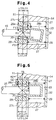
- the radial load FR applied to the drive shaft 16 during the compressing operation of the pistons 35 is received by the inner peripheral surface of the central bore 27 via the radial bearing 30 and the shutoff member 28. If the shutoff member 28 is caused to incline relative to the axis of the drive shaft 16, as shown in FIG. 4, because of external force such as vibration, the radial load FR can be broken into two components F11 and F12, which act in opposite directions, at contact points defined by the drive shaft 16 and the front and rear edges of the radial bearing 30, respectively, as shown in FIG. 4.
- M1 F11 ⁇ L11 + F12 ⁇ L11 + F13 ⁇ L13 + F14 ⁇ L14 Since the distances L11, L13 and L14 and the forces L11-L14 are all positive, M1 is also positive (i.e., M1>0).
- shutoff member 28 will not maintain the illustrated inclined position, but will be turned about the point 01 to contact the inner peripheral surface of the central bore 27 as shown in FIG. 5, whereupon the shutoff member 28 will resume alignment with the drive shaft 16.
- the radial load FR can be broken into two components F21 and F22 acting in the same direction at contact points defined by the drive shaft 16 and the front and rear edges of the radial bearing 30, respectively.
- a force F23 is developed at a contact point 02, which is defined by the outer peripheral surface of the large diameter section 28a of the shutoff member 28 and the front edge of the central bore 27, and another force F24 which is located at a contact point between the inner peripheral surface of the central bore 27 and the rear edge of the large diameter section 28a of the shutoff member 28.
- shutoff member 28 is subjected to a moment that acts around the point 02 and forces the shutoff member 28 into contact with the inner peripheral surface of the central bore 27. In other words, the shutoff member 28 is subjected to a moment that prevents it from inclining relative to the drive shaft 16.
- peripheral surface 27c on the front end of the cylinder block 11 adjacent the front opening of the central bore 27 is located forward of the axial center of the radial bearing 30 (or the axial center of the load bearing area between the radial bearing 30 and the shutoff member 28), as defined by the plane P, even when the shutoff member 28 is moved to its foremost position, that is, when the swash plate 22 is tilted to its maximum angle, the shutoff member 28 will not be inclined with respect to the drive shaft while the shutoff member 28 is moving toward the rear housing 13 in conjunction with the movement of the swash plate 22 from the maximum tilt angle position toward the minimum tilt angle position.
- shutoff member 28 can perform its intended function to securely shut off the suction passage 32 when the swash plate 22 is brought to the minimum tilt angle position when there is no cooling demand.
- the compressor performs its minimum displacement operation without introducing refrigerant gas into the suction chamber 37 from the suction passage 32.
- the entire front end surface of the cylinder block 11 including the peripheral surface 27a is formed flat, the tendency for the shutoff member 28 to incline is further suppressed. Moreover, the flat configuration of the front end surface is advantageous in machining the cylinder block 11.
- a separate fluid chamber may be provided in the compressor housing, instead of using the crankcase pressure Pc for the that purpose.
- the bleeding passage may be provided between the crankcase 15 and the suction chamber 37, and the displacement control valve assembly 49 is located in the bleeding passage.
- a clutch is usually connected between the vehicle engine and the drive shaft of the compressor.
- the compressor according to the invention may be connected to a clutch. In such a case, the clutch is kept engaged while the control switch 60 is on, but it is kept disengaged when the switch remains off, i.e., when there is no need for air conditioning and, therefore, the drive shaft of the compressor does not need be driven.
Landscapes
- Engineering & Computer Science (AREA)
- Mechanical Engineering (AREA)
- General Engineering & Computer Science (AREA)
- Compressors, Vaccum Pumps And Other Relevant Systems (AREA)
- Control Of Positive-Displacement Pumps (AREA)
- Magnetically Actuated Valves (AREA)
- Compressor (AREA)
Claims (3)
- Compresseur à déplacement variable comprenant :un boítier (11, 12) définissant une chambre de bielle (15), dans laquelle le boítier comporte un bloc cylindres (11) qui présente un alésage de cylindre (11a) et un alésage central (27), l'alésage central (27) ayant une surface cylindrique, dans laquelle l'alésage de cylindre (11a) et l'alésage central (27) ont des axes parallèles, et l'axe de l'alésage de cylindre (11a) est espacé radialement de l'axe de l'alésage central (27), dans lequel le bloc cylindres (11) présente une paroi avant (27c), la paroi avant (27) s'étendant radialement entre une ouverture avant de l'alésage central (27) jusqu'au moins l'alésage de cylindre (11a), et étant sensiblement perpendiculaire à l'axe de l'alésage central (27) ;un arbre d'entraínement (16) supporté par le boítier (11, 12), l'arbre d'entraínement (16) ayant une extrémité avant et une extrémité arrière, dans lequel une partie médiane de l'arbre d'entraínement (16) est située dans la chambre de bielle (15) et l'extrémité arrière de l'arbre d'entraínement (16) est située dans, et est coaxiale avec l'alésage central (27) ;un plateau oscillant (22) supporté par l'arbre d'entraínement (16), le plateau oscillant (22) étant supporté, pour pivoter, afin de tourner en une seule pièce avec l'arbre d'entraínement (16) et de s'incliner par rapport à un plan perpendiculaire à l'axe de l'arbre d'entraínement (16) entre une inclinaison maximale et une inclinaison minimale, dans lequel le plateau oscillant (22) se déplace généralement dans la direction axiale de l'arbre d'entraínement (16) lorsque l'inclinaison change ;un piston (35) situé dans l'alésage de cylindre (11a), le piston (35) étant raccordé au plateau oscillant (22), de telle sorte que la rotation du plateau oscillant (22) est convertie en un mouvement de va-et-vient du piston (35) et que la course du piston (35) est déterminée par l'inclinaison du plateau oscillant (22) ;un passage de fluide (32) présentant un orifice d'admission et un orifice de sortie, dans lequel le fluide s'écoule entre l'orifice d'admission et l'orifice de sortie par l'intermédiaire de l'alésage de cylindre (11a) ;un élément d'obturation cylindrique creux (28) situé dans l'alésage central (27) entre l'arbre d'entraínement (16) et la surface cylindrique pour fermer le passage de fluide (32), l'élément d'obturation (28) présentant une surface interne, dans laquelle l'élément d'obturation (28) se déplace axialement le long de l'alésage central (27), lorsque l'inclinaison du plateau oscillant (22) change de telle sorte que, lorsque l'inclinaison du plateau oscillant (22) augmente, l'élément d'obturation (28) suit le plateau oscillant (22) vers l'extrémité avant de l'arbre d'entraínement (16) et une section avant de l'élément d'obturation (28) n'est plus en contact avec la surface cylindrique de l'alésage central (27), dans lequel l'élément d'obturation (28) a une zone de support de charge radiale sur sa surface interne afin de supporter des charges radiales appliquées entre l'arbre d'entraínement (16) et l'élément d'obturation (28), dans lequel l'extrémité avant de l'alésage central (27) reste à l'avant d'un plan perpendiculaire à l'axe de l'arbre d'entraínement (16) qui coupe la zone de support de charge, quelle que soit la position axiale de l'élément d'obturation (28), caractérisé en ce que l'intégralité de la paroi avant (27c) du bloc cylindres est plane et présente une surface avant se trouvant dans un seul plan.
- Compresseur à déplacement variable de la revendication 1, dans lequel un palier (30) est situé entre l'élément d'obturation (28) et l'arbre d'entraínement (16) et la surface externe du palier (30) entre en contact avec la surface interne de l'élément d'obturation (28) au niveau de la zone de support de charge radiale.
- Compresseur à déplacement variable selon la revendication 1, dans lequel un circuit de conditionnement d'air est raccordé au passage de fluide.
Applications Claiming Priority (3)
| Application Number | Priority Date | Filing Date | Title |
|---|---|---|---|
| JP212389/96 | 1996-08-12 | ||
| JP8212389A JPH1054349A (ja) | 1996-08-12 | 1996-08-12 | 可変容量圧縮機 |
| JP21238996 | 1996-08-12 |
Publications (3)
| Publication Number | Publication Date |
|---|---|
| EP0824191A2 EP0824191A2 (fr) | 1998-02-18 |
| EP0824191A3 EP0824191A3 (fr) | 1999-06-09 |
| EP0824191B1 true EP0824191B1 (fr) | 2004-10-27 |
Family
ID=16621783
Family Applications (1)
| Application Number | Title | Priority Date | Filing Date |
|---|---|---|---|
| EP97113875A Expired - Lifetime EP0824191B1 (fr) | 1996-08-12 | 1997-08-11 | Compresseur à déplacement variable |
Country Status (7)
| Country | Link |
|---|---|
| US (1) | US6135722A (fr) |
| EP (1) | EP0824191B1 (fr) |
| JP (1) | JPH1054349A (fr) |
| KR (1) | KR100215155B1 (fr) |
| CN (1) | CN1102699C (fr) |
| CA (1) | CA2212705A1 (fr) |
| DE (1) | DE69731340T2 (fr) |
Families Citing this family (23)
| Publication number | Priority date | Publication date | Assignee | Title |
|---|---|---|---|---|
| JP3758399B2 (ja) * | 1999-01-18 | 2006-03-22 | 株式会社豊田自動織機 | 可変容量型圧縮機における容量制御弁取り付け構造 |
| JP4505976B2 (ja) * | 2000-01-11 | 2010-07-21 | 株式会社豊田自動織機 | ピストン式圧縮機 |
| JP2006022785A (ja) * | 2004-07-09 | 2006-01-26 | Toyota Industries Corp | 容量可変型圧縮機 |
| US7997880B2 (en) * | 2005-08-12 | 2011-08-16 | Halla Climate Control Corporation | Compressor |
| US7585222B2 (en) * | 2005-08-17 | 2009-09-08 | Igt | Gaming device and method providing a near miss insurance pool or fund |
| CN101358585B (zh) * | 2008-09-11 | 2011-11-16 | 谌小堰 | 斜曲轴变量柱塞泵 |
| KR101083671B1 (ko) | 2009-11-24 | 2011-11-16 | 주식회사 두원전자 | 용량가변형 압축기의 용량제어밸브 |
| KR101083678B1 (ko) | 2009-11-24 | 2011-11-16 | 주식회사 두원전자 | 용량가변형 압축기의 용량제어밸브 |
| KR101631217B1 (ko) * | 2009-11-24 | 2016-06-17 | 학교법인 두원학원 | 용량가변형 압축기의 용량제어밸브 |
| WO2011065693A2 (fr) * | 2009-11-24 | 2011-06-03 | 두원공과대학교 | Vanne de commande de cylindrée pour compresseur à cylindrée variable |
| JP6191527B2 (ja) | 2014-03-28 | 2017-09-06 | 株式会社豊田自動織機 | 容量可変型斜板式圧縮機 |
| JP6179439B2 (ja) * | 2014-03-28 | 2017-08-16 | 株式会社豊田自動織機 | 容量可変型斜板式圧縮機 |
| JP6194836B2 (ja) | 2014-03-28 | 2017-09-13 | 株式会社豊田自動織機 | 容量可変型斜板式圧縮機 |
| JP6194837B2 (ja) | 2014-03-28 | 2017-09-13 | 株式会社豊田自動織機 | 容量可変型斜板式圧縮機 |
| JP6179438B2 (ja) | 2014-03-28 | 2017-08-16 | 株式会社豊田自動織機 | 容量可変型斜板式圧縮機 |
| JP6287483B2 (ja) | 2014-03-28 | 2018-03-07 | 株式会社豊田自動織機 | 容量可変型斜板式圧縮機 |
| CN105351164B (zh) * | 2015-10-26 | 2017-09-12 | 江苏恒立液压科技有限公司 | 轴向柱塞泵电比例扭矩控制装置及其控制方法 |
| CN107120251B (zh) * | 2017-06-18 | 2020-06-19 | 苏州欧圣电气股份有限公司 | 柱塞泵及清洗机 |
| CN107816422A (zh) * | 2017-10-13 | 2018-03-20 | 浙江大学 | 汽车空调压缩机一体式斜盘 |
| CN115362316A (zh) | 2020-03-31 | 2022-11-18 | 固瑞克明尼苏达有限公司 | 电动操作的往复式泵 |
| CN115362317A (zh) | 2020-03-31 | 2022-11-18 | 固瑞克明尼苏达有限公司 | 电动线性泵 |
| CN115335601A (zh) | 2020-03-31 | 2022-11-11 | 固瑞克明尼苏达有限公司 | 用于多组分喷涂系统的电操作泵 |
| DE102020215275A1 (de) * | 2020-12-03 | 2022-06-09 | Mahle International Gmbh | Expansionsventil |
Family Cites Families (15)
| Publication number | Priority date | Publication date | Assignee | Title |
|---|---|---|---|---|
| JPH0413425Y2 (fr) * | 1988-04-28 | 1992-03-27 | ||
| KR970004811B1 (ko) * | 1993-06-08 | 1997-04-04 | 가부시끼가이샤 도요다 지도쇽끼 세이샤꾸쇼 | 무클러치 편측 피스톤식 가변 용량 압축기 및 그 용량 제어방법 |
| US5577894A (en) * | 1993-11-05 | 1996-11-26 | Kabushiki Kaisha Toyoda Jidoshokki Seisakusho | Piston type variable displacement compressor |
| JP3254853B2 (ja) * | 1993-11-05 | 2002-02-12 | 株式会社豊田自動織機 | クラッチレス片側ピストン式可変容量圧縮機 |
| JP3254872B2 (ja) * | 1993-12-27 | 2002-02-12 | 株式会社豊田自動織機 | クラッチレス片側ピストン式可変容量圧縮機 |
| US5603610A (en) * | 1993-12-27 | 1997-02-18 | Kabushiki Kaisha Toyoda Jidoshokki Seisakusho | Clutchless piston type variable displacement compressor |
| JP3503179B2 (ja) * | 1994-04-15 | 2004-03-02 | 株式会社豊田自動織機 | クラッチレス片側ピストン式可変容量圧縮機 |
| US5584670A (en) * | 1994-04-15 | 1996-12-17 | Kabushiki Kaisha Toyoda Jidoshokki Seisakusho | Piston type variable displacement compressor |
| US5681150A (en) * | 1994-05-12 | 1997-10-28 | Kabushiki Kaisha Toyoda Jidoshokki Seisakusho | Piston type variable displacement compressor |
| JPH07310654A (ja) * | 1994-05-12 | 1995-11-28 | Toyota Autom Loom Works Ltd | クラッチレス片側ピストン式可変容量圧縮機 |
| US5624240A (en) * | 1994-06-27 | 1997-04-29 | Kabushiki Kaisha Toyoda Jidoshokki Seisakusho | Piston type variable displacement compressor |
| JPH08109880A (ja) * | 1994-10-11 | 1996-04-30 | Toyota Autom Loom Works Ltd | 可変容量型圧縮機の動作制御システム |
| JP2932952B2 (ja) * | 1994-12-07 | 1999-08-09 | 株式会社豊田自動織機製作所 | クラッチレス可変容量型圧縮機 |
| KR100202784B1 (ko) * | 1995-03-30 | 1999-06-15 | 이소가이 치세이 | 가변용량 압축기 |
| KR100203975B1 (ko) * | 1995-10-26 | 1999-06-15 | 이소가이 치세이 | 캠 플레이트식 가변용량 압축기 |
-
1996
- 1996-08-12 JP JP8212389A patent/JPH1054349A/ja active Pending
-
1997
- 1997-07-30 KR KR1019970036093A patent/KR100215155B1/ko not_active Expired - Fee Related
- 1997-08-11 DE DE69731340T patent/DE69731340T2/de not_active Expired - Fee Related
- 1997-08-11 EP EP97113875A patent/EP0824191B1/fr not_active Expired - Lifetime
- 1997-08-11 US US08/909,708 patent/US6135722A/en not_active Expired - Fee Related
- 1997-08-11 CA CA002212705A patent/CA2212705A1/fr not_active Abandoned
- 1997-08-12 CN CN97118082A patent/CN1102699C/zh not_active Expired - Fee Related
Also Published As
| Publication number | Publication date |
|---|---|
| JPH1054349A (ja) | 1998-02-24 |
| DE69731340D1 (de) | 2004-12-02 |
| EP0824191A3 (fr) | 1999-06-09 |
| CN1102699C (zh) | 2003-03-05 |
| CN1185531A (zh) | 1998-06-24 |
| KR100215155B1 (ko) | 1999-08-16 |
| US6135722A (en) | 2000-10-24 |
| EP0824191A2 (fr) | 1998-02-18 |
| DE69731340T2 (de) | 2006-03-09 |
| KR19980018248A (ko) | 1998-06-05 |
| CA2212705A1 (fr) | 1998-02-12 |
Similar Documents
| Publication | Publication Date | Title |
|---|---|---|
| EP0824191B1 (fr) | Compresseur à déplacement variable | |
| US5890876A (en) | Control valve in variable displacement compressor | |
| US6358017B1 (en) | Control valve for variable displacement compressor | |
| US6062823A (en) | Control valve in variable displacement compressor | |
| EP1059443B1 (fr) | Soupape de contrôle de capacité | |
| US5964578A (en) | Control valve in variable displacement compressor | |
| US5865604A (en) | Displacement controlling structure for clutchless variable displacement compressor | |
| US6010312A (en) | Control valve unit with independently operable valve mechanisms for variable displacement compressor | |
| US6234763B1 (en) | Variable displacement compressor | |
| US5586870A (en) | Bearing structure used in a compressor | |
| JPH102284A (ja) | 可変容量圧縮機及びその制御方法 | |
| US5975859A (en) | Control valve in variable displacement compressor and its assembling method | |
| US5616008A (en) | Variable displacement compressor | |
| US6863503B2 (en) | Variable capacity compressor | |
| US6077047A (en) | Variable displacement compressor | |
| US6217291B1 (en) | Control valve for variable displacement compressors and method for varying displacement | |
| US20020094278A1 (en) | Apparatus and method for controlling variable displacement compressor | |
| JP3254872B2 (ja) | クラッチレス片側ピストン式可変容量圧縮機 | |
| US6076449A (en) | Variable displacement compressor | |
| EP1033489A2 (fr) | Soupape de contrôle pour compresseurs à capacité variable | |
| US6578372B2 (en) | Apparatus and method for controlling variable displacement compressor | |
| JPH07286581A (ja) | クラッチレス片側ピストン式可変容量圧縮機 | |
| CA2221475C (fr) | Compresseur a cylindree variable | |
| EP1207302B1 (fr) | Soupape de commande pour un compresseur à capacité variable | |
| JP3214354B2 (ja) | クラッチレス可変容量圧縮機 |
Legal Events
| Date | Code | Title | Description |
|---|---|---|---|
| PUAI | Public reference made under article 153(3) epc to a published international application that has entered the european phase |
Free format text: ORIGINAL CODE: 0009012 |
|
| 17P | Request for examination filed |
Effective date: 19970811 |
|
| AK | Designated contracting states |
Kind code of ref document: A2 Designated state(s): DE FR GB IT |
|
| PUAL | Search report despatched |
Free format text: ORIGINAL CODE: 0009013 |
|
| AK | Designated contracting states |
Kind code of ref document: A3 Designated state(s): AT BE CH DE DK ES FI FR GB GR IE IT LI LU MC NL PT SE |
|
| AKX | Designation fees paid |
Free format text: DE FR GB IT |
|
| RAP1 | Party data changed (applicant data changed or rights of an application transferred) |
Owner name: KABUSHIKI KAISHA TOYOTA JIDOSHOKKI |
|
| 17Q | First examination report despatched |
Effective date: 20030130 |
|
| GRAP | Despatch of communication of intention to grant a patent |
Free format text: ORIGINAL CODE: EPIDOSNIGR1 |
|
| GRAS | Grant fee paid |
Free format text: ORIGINAL CODE: EPIDOSNIGR3 |
|
| GRAA | (expected) grant |
Free format text: ORIGINAL CODE: 0009210 |
|
| AK | Designated contracting states |
Kind code of ref document: B1 Designated state(s): DE FR GB IT |
|
| REG | Reference to a national code |
Ref country code: GB Ref legal event code: FG4D |
|
| REF | Corresponds to: |
Ref document number: 69731340 Country of ref document: DE Date of ref document: 20041202 Kind code of ref document: P |
|
| PG25 | Lapsed in a contracting state [announced via postgrant information from national office to epo] |
Ref country code: IT Free format text: LAPSE BECAUSE OF NON-PAYMENT OF DUE FEES;WARNING: LAPSES OF ITALIAN PATENTS WITH EFFECTIVE DATE BEFORE 2007 MAY HAVE OCCURRED AT ANY TIME BEFORE 2007. THE CORRECT EFFECTIVE DATE MAY BE DIFFERENT FROM THE ONE RECORDED. Effective date: 20050811 Ref country code: GB Free format text: LAPSE BECAUSE OF NON-PAYMENT OF DUE FEES Effective date: 20050811 |
|
| PLBE | No opposition filed within time limit |
Free format text: ORIGINAL CODE: 0009261 |
|
| STAA | Information on the status of an ep patent application or granted ep patent |
Free format text: STATUS: NO OPPOSITION FILED WITHIN TIME LIMIT |
|
| ET | Fr: translation filed | ||
| 26N | No opposition filed |
Effective date: 20050728 |
|
| PG25 | Lapsed in a contracting state [announced via postgrant information from national office to epo] |
Ref country code: DE Free format text: LAPSE BECAUSE OF NON-PAYMENT OF DUE FEES Effective date: 20060301 |
|
| GBPC | Gb: european patent ceased through non-payment of renewal fee |
Effective date: 20050811 |
|
| PG25 | Lapsed in a contracting state [announced via postgrant information from national office to epo] |
Ref country code: FR Free format text: LAPSE BECAUSE OF NON-PAYMENT OF DUE FEES Effective date: 20060428 |
|
| REG | Reference to a national code |
Ref country code: FR Ref legal event code: ST Effective date: 20060428 |