EP0824215A2 - Entfernungsmessgerät unter Verwendug einer modulierten Lichtquelle und Erkennung mittels Phasenverschiebung - Google Patents
Entfernungsmessgerät unter Verwendug einer modulierten Lichtquelle und Erkennung mittels Phasenverschiebung Download PDFInfo
- Publication number
- EP0824215A2 EP0824215A2 EP97113993A EP97113993A EP0824215A2 EP 0824215 A2 EP0824215 A2 EP 0824215A2 EP 97113993 A EP97113993 A EP 97113993A EP 97113993 A EP97113993 A EP 97113993A EP 0824215 A2 EP0824215 A2 EP 0824215A2
- Authority
- EP
- European Patent Office
- Prior art keywords
- light
- intensity
- phase difference
- light beam
- measuring apparatus
- Prior art date
- Legal status (The legal status is an assumption and is not a legal conclusion. Google has not performed a legal analysis and makes no representation as to the accuracy of the status listed.)
- Withdrawn
Links
- 238000001514 detection method Methods 0.000 title description 12
- 230000010363 phase shift Effects 0.000 title 1
- 230000001105 regulatory effect Effects 0.000 claims description 7
- 230000010287 polarization Effects 0.000 claims description 6
- 230000001276 controlling effect Effects 0.000 claims 1
- 230000003287 optical effect Effects 0.000 abstract description 44
- 239000004973 liquid crystal related substance Substances 0.000 abstract description 11
- 238000005259 measurement Methods 0.000 description 12
- 238000010586 diagram Methods 0.000 description 3
- 239000004065 semiconductor Substances 0.000 description 3
- 230000002238 attenuated effect Effects 0.000 description 2
- 230000033228 biological regulation Effects 0.000 description 2
- 238000006243 chemical reaction Methods 0.000 description 2
- 230000005374 Kerr effect Effects 0.000 description 1
- 230000005540 biological transmission Effects 0.000 description 1
- 239000000284 extract Substances 0.000 description 1
- 239000000463 material Substances 0.000 description 1
- 230000001902 propagating effect Effects 0.000 description 1
Images

Classifications
-
- G—PHYSICS
- G01—MEASURING; TESTING
- G01S—RADIO DIRECTION-FINDING; RADIO NAVIGATION; DETERMINING DISTANCE OR VELOCITY BY USE OF RADIO WAVES; LOCATING OR PRESENCE-DETECTING BY USE OF THE REFLECTION OR RERADIATION OF RADIO WAVES; ANALOGOUS ARRANGEMENTS USING OTHER WAVES
- G01S7/00—Details of systems according to groups G01S13/00, G01S15/00, G01S17/00
- G01S7/48—Details of systems according to groups G01S13/00, G01S15/00, G01S17/00 of systems according to group G01S17/00
- G01S7/491—Details of non-pulse systems
- G01S7/493—Extracting wanted echo signals
-
- G—PHYSICS
- G01—MEASURING; TESTING
- G01S—RADIO DIRECTION-FINDING; RADIO NAVIGATION; DETERMINING DISTANCE OR VELOCITY BY USE OF RADIO WAVES; LOCATING OR PRESENCE-DETECTING BY USE OF THE REFLECTION OR RERADIATION OF RADIO WAVES; ANALOGOUS ARRANGEMENTS USING OTHER WAVES
- G01S17/00—Systems using the reflection or reradiation of electromagnetic waves other than radio waves, e.g. lidar systems
- G01S17/02—Systems using the reflection of electromagnetic waves other than radio waves
- G01S17/06—Systems determining position data of a target
- G01S17/08—Systems determining position data of a target for measuring distance only
- G01S17/32—Systems determining position data of a target for measuring distance only using transmission of continuous waves, whether amplitude-, frequency-, or phase-modulated, or unmodulated
- G01S17/36—Systems determining position data of a target for measuring distance only using transmission of continuous waves, whether amplitude-, frequency-, or phase-modulated, or unmodulated with phase comparison between the received signal and the contemporaneously transmitted signal
-
- G—PHYSICS
- G01—MEASURING; TESTING
- G01S—RADIO DIRECTION-FINDING; RADIO NAVIGATION; DETERMINING DISTANCE OR VELOCITY BY USE OF RADIO WAVES; LOCATING OR PRESENCE-DETECTING BY USE OF THE REFLECTION OR RERADIATION OF RADIO WAVES; ANALOGOUS ARRANGEMENTS USING OTHER WAVES
- G01S7/00—Details of systems according to groups G01S13/00, G01S15/00, G01S17/00
- G01S7/48—Details of systems according to groups G01S13/00, G01S15/00, G01S17/00 of systems according to group G01S17/00
- G01S7/491—Details of non-pulse systems
- G01S7/4912—Receivers
- G01S7/4918—Controlling received signal intensity, gain or exposure of sensor
Definitions
- This invention relates to a distance measuring apparatus which emits modulated light toward an object and receives reflected light from the object to determine a distance from the object.
- the basic idea of a distance measuring apparatus using an optical wave is to emit modulated light toward an object, receive reflected light from the object, and measure a phase difference between the emitted light wave and the received light wave. The distance from the object is determined based on the phase difference and the wave length of the modulated light.
- This type of distance measuring apparatus utilizes a low frequency for rough-range measurement and a high frequency for precise-range measurement according to the relation between the distance from the object and the wave length of modulated light.
- the distance measuring apparatus receives a light beam reflected by the object, and converts the received light into an electric signal.
- the phase difference between the transmitted light and the received light is detected in an electric circuit after performing a photoelectric conversion.
- the phase detected by the electric circuit often fluctuates due changes in temperature.
- it has been proposed to provide a reference optical path within a distance measuring apparatus in, for example, Japanese utility model publication No. 52-34999. More specifically, the error which occurs in the measuring circuit is canceled by subtracting a reference distance, which is determined based on a phase difference obtained from the reference optical path, from a measured distance which, in turn, is determined based on a phase difference obtained from the actual measurement optical path.
- Phase fluctuation also occurs because a signal level within the measuring circuit differs according to a difference in the intensity of received light, due to a limit of the dynamic range of the measuring circuit.
- Japanese patent application publication Nos. 51-8338, 51-8339, and 51-8340 propose to provide a light intensity regulation means in the range-measuring optical path or the reference optical path to make the light intensity from the range-measuring optical path substantially equal to the light intensity from the reference optical path, so that the intensity of the received light falls within the linear range of the measuring circuit.
- the maximum light-receiving amount becomes relatively low. As a result, the maximum measurable range becomes very limited
- the reduction in maximum light-receiving amount also limits the range of objects which are subject to distance measurement.
- the maximum light transmissivity is typically reduced by at least 20 percent (%). This makes it impossible to measure a long distance or a distance from an object having a very low reflectance, because in such instances the light intensity received by the measuring apparatus is insufficient.
- the phase difference detector must have a dynamic range equal or equivalent to the dynamic range of the received light intensity from the range-measuring optical path.
- a measuring circuit which remains linear over a wide range is expensive. Furthermore, it is difficult for this type of measuring instrument to improve the measuring accuracy.
- It is another object of the invention to provide a distance measuring apparatus for measuring a distance from an object using an optical wave which includes a light intensity regulator that adjusts a light intensity received from a range-measuring optical path so as to be substantially equal to a light intensity received from a reference optical path.
- the light intensity regulator uses a light intensity control element, such as liquid crystal, which does not need a mechanical drive.
- a distance measuring apparatus has a light source for emitting a light beam toward an object. A light beam reflected from the object is received by the distance measuring apparatus. The distance measuring apparatus determines a distance between the light source and the object based on a phase difference between a received signal obtained from the reflected light and a reference signal obtained from reference light which is a direct light beam from the light source. A light receiving unit receives the reflected light and the reference light, and photoelectrically converts them into the received signal and the reference signal, respectively. A level adjustor adjusts the level (e.g., magnitude or amplitude) of the received signal to a predetermined allowable level according to the quantity of the reflected light.
- level e.g., magnitude or amplitude
- a light intensity regulator is positioned between the light source and the light receiving unit, and regulates the light intensity of the reference light so as to be the same level as the reflected light or within a predetermined range therefrom.
- a phase difference detector detects a phase difference between the received signal, which has passed through the level adjustor, and the reference signal, which has passed through the light intensity regulator.
- the intensity of the deference light is made substantially equal to the intensity of the measuring (reflected) light through the light intensity regulator prior to being supplied to the phase difference detector.
- the level of the received signal obtained from the reflected light is also adjusted prior to being supplied to the phase difference detector, so that the level falls within the dynamic range of the phase difference detector. Accordingly, even if the intensity of the measuring (reflected) light is insufficient and the level of the received signal is low, the distance from the object can be reliably measured because the intensity of the received light and the intensity of the reference light are made substantially equal.
- the dynamic range of the phase difference detector can be narrowed.
- the light intensity regulator comprises a plurality of polarizers and polarization control elements, such as liquid crystal, inserted between the polarizers. This arrangement does not need a mechanical drive.
- the transmissivity is changed by a control signal which is, for example, a voltage applied to the polarization control elements.
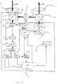
- Fig. 1 is a diagram showing the principle of the present invention.
- the elements shown in Fig. 1, other than the object that is to be measured, constitute a distance measuring apparatus.
- a modulated signal having a frequency that matches the range of the object is supplied to the light source 3.
- the electric signal is converted to light, which is then transmitted along the range-measuring optical path 30A to the object.
- the light is reflected from the object, and returns along the rang-measuring optical return path 30B to the photoelectric converter 8 which serves as a light-receiving unit.
- the range-measuring optical paths 30A and 30B essentially do not include any elements that attenuate the light intensity.
- the maximum measurable distance is maintained large and many different types of objects may be the subject of the distance measurement.
- a reference optical path 16 is formed within the distance measuring apparatus.
- the light emitted from the light source is guided through a beam splitter 15 and a beam combiner 17 along the reference optical path 16 to the photoelectric converter 8.
- This light beam directly guided from the light source to the photoelectric converter 8 is designated as the reference light.
- the intensity of the reference light Is adjusted by the light intensity regulator 19 so as to be substantially equal to the intensity of the reflected range-measuring light or within an allowable range therefrom. More specifically, the level of the electric signal resulting from the photoelectric conversion of the reflected range-measuring light by the photoelectric converter 8 represents the reflected range-measuring light and is detected by the light intensity detector 21.
- a signal indicative of the level of this electric signal is then supplied to the CPU 2.
- the CPU 2 supplies a control signal based on the detection result to the light intensity regulator 19.
- the light intensity regulator 19 adjusts the intensity of the reference light based on the control signal from the CPU 2.
- the light intensity regulator 19 is, for example, of a liquid crystal type, in which liquid crystal is inserted between a plurality of polarizers. The light transmissivity of the liquid crystal changes in response to a change in a voltage applied thereto, thereby adjusting the overall light transmission.
- This type of light intensity regulator is advantageous because it does not require a mechanical drive and is reliable because of its lack of vibration. Also, the response of the liquid crystal is advantageously quick.
- the level of the electric signal representative of the reflected range-measuring light is regulated by the CPU 2. As has been described, the level of the electric signal is detected by the light intensity detector 21. The gain of the gain control amplifier 14 is regulated by the CPU 2 so that the detected level of the electric signal falls within a dynamic range of the phase difference detector 20. In other words, a received signal having a regulated level is supplied to the phase difference detector 20.
- phase difference detector 20 Only those signals whose levels are within the dynamic range of the phase difference detector 20 are supplied to the phase difference detector 20. Therefore, a phase difference can be measured in a range with a high linearity, allowing a highly accurate detection.
- Fig. 2 illustrates the detailed structure of a distance measuring apparatus according to an embodiment of the invention.
- the oscillator 1 generates signals having, for example, five different frequencies, namely, modulation frequencies fT1, fT2 for the light source 3, a phase-detection frequency f1F, and demodulation frequencies fR1 (which equals fT1-f1F) and fR2 (which equals to fT2-f1F).
- the modulation frequency fT1 is used for precise measurement of a distance, and is set relatively high, e.g., 15MHz.
- the other modulation frequency fT2 is used for rough measurement, and is set relatively low, e.g., 75KHz.
- the two modulation frequencies are selectively used according to a command signal supplied from the CPU 2.
- the modulation frequencies fT1 and fT2 are supplied to the light source 3, and the demodulation frequencies fR1 and fR2 are supplied to the light-receiving unit 8.
- the drive circuit 4 generates a driving signal from the modulation frequency signal fTn to drive the semiconductor laser diode 5.
- the semiconductor laser diode 5 emits modulated light.
- the light emitted from the light source 3 is shaped by the light-transmitting objective lens 6, and guided to the object.
- the light is reflected by the object, collected by the light-receiving objective lens 7, and enters the light-receiving unit 8.
- the light-receiving unit 8 is a photoelectric converter which includes an avalanche photodiode 9, a bias circuit 10 for the avalanche photodiode 9, a filter 12 and an amplifier 13.
- a demodulation frequency fRn selected by the CPU 2 is supplied from the oscillator 1 to the bias circuit 10, and a bias voltage having that demodulation frequency is applied to the avalanche photodiode (APD) 9.
- a demodulation frequency fRn selected by the CPU 2 is supplied from the oscillator 1 to the bias circuit 10, and
- the gain of an avalanche photodiode varies in response to a bias voltage applied thereto. Accordingly, when a demodulation frequency fRn is applied as a bias voltage to the avalanche photodiode (APD) 9, the output of the APD 9 has a phase-detection frequency component f1F which is a difference (fTn-fRn) between the modulation frequency fTn and the demodulation frequency fRn. The output of the APD 9 maintains a phase difference ⁇ of the received signal.
- This operation is generally known as heterodyne demodulation, which is used when converting the frequency component of a high frequency signal to a low frequency without disturbing the phase component. Through this operation, the received rang-measuring signal becomes a low frequency signal.
- the phase difference detector 20 will detect a phase difference of the received signal in its low frequency form which, in turn, facilitates phase detection while maintaining high accuracy.
- the photoelectrically converted signal is supplied from the APD 9 to the filter 12 which extracts the range-measuring frequency component of the electric signal.
- the electric signal which has passed through the filter 12 is amplified by the amplifier 13, and supplied to the gain control amplifier 14.
- the light beam emitted from the light source 3 is split by the splitter 15.
- the split light component is guided to the light-receiving unit 8 through the light combining unit 17 along the reference optical path 16.
- An optical path switching unit 18, which is constructed as, for example, a mechanical shutter, is positioned before the light combining unit 17.
- the optical path switching unit 18 selectively allows passage of either the reference optical path or the range-measuring optical path, and blocks the other, according to a command signal from the CPU 2.
- a light intensity regulator 19 is provided on the reference optical path 16.
- the light intensity regulator 19 controls the light intensity in the reference optical path based on a command signal from the CPU 2, so that the light intensity in the reference optical path becomes substantially equal to the light intensity in the rang-measuring optical path.
- the light intensity regulator may be of an ordinary mechanical type having a mechanical drive for changing the angle between two polarizers.
- a polarization control element such as liquid crystal
- a Kerr cell utilizing the Kerr effect or a Pockels cell may be used to control the transmissivity according to a voltage applied thereto.
- the gain control amplifier 14 controls its gain according to a control signal from the CPU 2.
- the gain control amplifier 14 appropriately amplifies the level of the input signal which has been photoelectrically converted into an electric signal by the light-receiving unit 8, and supplies the amplified signal to the phase difference detector 20 through the phase shifter 22.
- the dynamic range of the phase difference detector 20 is designed to be relatively narrow, the detection accuracy is high because the electric signal is modified by the gain control amplifier 14 so as to have a level within the dynamic range of the phase difference detector 20.
- the light intensity detector 21 determines the Intensity of the received (reflected) light based on the output of the gain control amplifier 14.
- the output of the light intensity detector 21 is supplied to the CPU 2 for gain adjustment.
- the CPU 2 supplies a gain control signal to the gain control amplifier 14 according to the output signal from the light intensity detector 21.
- the phase difference detector 20 When the phase difference detector 20 receives the received reflected signal that has been adjusted to a certain level, the phase difference detector 20 detects a phase difference ⁇ a between the received signal and the transmitted signal, having a range-measuring frequency f1F. Similarly, the reference light received from the reference optical path is amplified with a gain, and supplied to the phase difference detector 20. The phase difference detector 20 detects a phase difference ⁇ b between the reference signal and the transmitted signal with the frequency f1F. The distance from the object is calculated by the CPU 2 according to formula (1). The calculation result is displayed on the monitor 23.
- the phase shifter is designed to appropriately take an average of the detected phase difference values. If the phase difference detected by the phase difference detector 20 is around 0°, the detection result will become, for example, 0° or 364° depending on the detection error. In such a case, a correct average cannot be obtained from multiple rounds of phase difference detection. Therefore, the phase shifter 22 is provided to shirt the detected phase by a certain degree as a shifting amount, thereby avoiding an incorrect average calculation. The phase shifter 22 subtracts the shifting amount from the average. The shifting amount of the phase shifter 22 is controlled by the CPU 2.
- the gain control amplifier 14 sets the level of a received signal.
- the optical path switching unit 18 selects the range-measuring optical path 30B according to a command from the CPU 2.
- the gain of the gain control amplifier 14 is set to an appropriate value.
- the modulation frequency and the demodulation frequency are set to appropriate values in the oscillator 1.
- the selected modulation frequency is supplied to the light source 3, and the demodulation frequency is supplied to the light-receiving unit 8.
- the semiconductor laser of the light source 3 emits a laser beam having the selected modulation frequency toward the object.
- the light-receiving unit 8 receives a reflected laser beam from the object.
- the received beam is converted to an electric signal, the level of which is measured by the light intensity detector 21.
- the CPU 2 compares the level of the electric signal with a predetermined optimum level of a received signal, and changes the gain of the gain control amplifier 14 so that the level of the electric signal becomes most suitable to the phase difference detector 20.
- the optical path switching unit 18 selects the reference optical path 16.
- the gain of the gain control amplifier 14 maintains the same value.
- the CPU 2 changes the attenuation amount of the light intensity regulator 19 so that the light intensity from the reference optical path achieves an optimal intensity level. As a result, the level of the reference signal detected by the light intensity detector 21 is optimized.
- the phases of the signals from the range-measuring optical path 30 and the reference optical path 16 are detected based on the modulation and demodulation frequencies for precise measurement and the modulation and demodulation frequencies for rough measurement. Using the detection result, the distance from the object is calculated according to formula (1).
- phase difference detector 20 In this arrangement, a range-measuring light and a reference light which have optimum signal levels are supplied to the phase difference detector 20.
- the phase difference detector 20 can detect the phase difference based on the optimum signal levels. Even if an inexpensive phase detector with a relatively narrow dynamic range is used in the distance measuring apparatus, a phase difference can be detected with high accuracy. While the intensity of the reference light is attenuated by the light intensity-regulator 19, the intensity of the range-measuring light is not attenuated. Therefore, the maximum measurable range and types of objects which are subject to distance measurement are both maximized.
- a light intensity regulator is not provided in the range-measuring optical path, and detection of distances to a broad range of objects located at far distances can be achieved.
- a light intensity regulator is provided on the reference path to regulate the light intensity in the reference optical path so that it matches the intensity of the range-measuring light beam.
- the gain control amplifier adjusts the level of a received signal to the optimum level suitable to the phase difference detector.
- liquid crystal is used in the light intensity regulator to eliminate the need for a mechanical drive, whereby light intensity is regulated quickly and precisely.
Landscapes
- Engineering & Computer Science (AREA)
- Physics & Mathematics (AREA)
- Computer Networks & Wireless Communication (AREA)
- General Physics & Mathematics (AREA)
- Radar, Positioning & Navigation (AREA)
- Remote Sensing (AREA)
- Electromagnetism (AREA)
- Optical Radar Systems And Details Thereof (AREA)
- Length Measuring Devices By Optical Means (AREA)
- Measurement Of Optical Distance (AREA)
- Photometry And Measurement Of Optical Pulse Characteristics (AREA)
- Radar Systems Or Details Thereof (AREA)
Applications Claiming Priority (2)
| Application Number | Priority Date | Filing Date | Title |
|---|---|---|---|
| JP215711/96 | 1996-08-15 | ||
| JP8215711A JPH1062549A (ja) | 1996-08-15 | 1996-08-15 | 距離測定装置 |
Publications (2)
| Publication Number | Publication Date |
|---|---|
| EP0824215A2 true EP0824215A2 (de) | 1998-02-18 |
| EP0824215A3 EP0824215A3 (de) | 1998-07-22 |
Family
ID=16676907
Family Applications (1)
| Application Number | Title | Priority Date | Filing Date |
|---|---|---|---|
| EP97113993A Withdrawn EP0824215A3 (de) | 1996-08-15 | 1997-08-13 | Entfernungsmessgerät unter Verwendug einer modulierten Lichtquelle und Erkennung mittels Phasenverschiebung |
Country Status (2)
| Country | Link |
|---|---|
| EP (1) | EP0824215A3 (de) |
| JP (1) | JPH1062549A (de) |
Cited By (5)
| Publication number | Priority date | Publication date | Assignee | Title |
|---|---|---|---|---|
| EP1499852A4 (de) * | 2002-04-15 | 2008-11-19 | Toolz Ltd | Distanzmesseinrichtung mit kurzdistanzoptik |
| EP1955014A4 (de) * | 2005-11-28 | 2008-12-03 | Robotoolz Ltd | Distanzmesseinrichtung mit einer optik mit kurzer reichweite |
| WO2011079497A1 (zh) * | 2009-12-29 | 2011-07-07 | 江苏徕兹光电科技有限公司 | 基于液晶光阀原理相位测量的校准方法和校准装置 |
| CN113671516A (zh) * | 2021-08-05 | 2021-11-19 | 湖南大学 | 一种车灯测距装置及其方法 |
| CN115616539A (zh) * | 2022-11-07 | 2023-01-17 | 杭州隆硕科技有限公司 | 脉冲式测距系统误差的补偿系统和补偿方法 |
Families Citing this family (5)
| Publication number | Priority date | Publication date | Assignee | Title |
|---|---|---|---|---|
| JP2006329797A (ja) * | 2005-05-26 | 2006-12-07 | Sokkia Co Ltd | 光波距離計 |
| JP5665159B2 (ja) * | 2007-02-23 | 2015-02-04 | パナソニックIpマネジメント株式会社 | 距離画像センサ |
| JP6241283B2 (ja) * | 2014-01-06 | 2017-12-06 | 株式会社豊田中央研究所 | レーダ装置および距離速度測定方法 |
| JP2019174351A (ja) * | 2018-03-29 | 2019-10-10 | 株式会社トプコン | 測量装置 |
| USD981252S1 (en) | 2019-08-13 | 2023-03-21 | Coldsnap, Corp. | Pod for use with a food or drink machine |
Family Cites Families (6)
| Publication number | Priority date | Publication date | Assignee | Title |
|---|---|---|---|---|
| US3779645A (en) * | 1970-05-20 | 1973-12-18 | Nippon Kogaku Kk | Distance measuring device |
| US3752582A (en) * | 1971-01-27 | 1973-08-14 | Bendix Corp | Optical range and range-rate sensor |
| US3900261A (en) * | 1974-03-18 | 1975-08-19 | Transitek Corp | Electronic range finder |
| FR2310581A1 (fr) * | 1975-05-07 | 1976-12-03 | Thomson Csf | Attenuateur optique a commande electrique |
| DE3103567A1 (de) * | 1981-02-03 | 1982-08-12 | MITEC Moderne Industrietechnik GmbH, 8012 Ottobrunn | Entfernungsmessverfahren nach dem prinzip der laufzeitmessung eines messlichtimpulses und vorrichtung zu seiner durchfuehrung |
| US4498764A (en) * | 1981-06-09 | 1985-02-12 | Ludwig Bolkow | Dynamic control arrangement for a distance measuring apparatus |
-
1996
- 1996-08-15 JP JP8215711A patent/JPH1062549A/ja active Pending
-
1997
- 1997-08-13 EP EP97113993A patent/EP0824215A3/de not_active Withdrawn
Cited By (8)
| Publication number | Priority date | Publication date | Assignee | Title |
|---|---|---|---|---|
| EP1499852A4 (de) * | 2002-04-15 | 2008-11-19 | Toolz Ltd | Distanzmesseinrichtung mit kurzdistanzoptik |
| US7499150B2 (en) | 2002-04-15 | 2009-03-03 | Robert Bosch Company Limited | Distance measurement device |
| EP1955014A4 (de) * | 2005-11-28 | 2008-12-03 | Robotoolz Ltd | Distanzmesseinrichtung mit einer optik mit kurzer reichweite |
| WO2011079497A1 (zh) * | 2009-12-29 | 2011-07-07 | 江苏徕兹光电科技有限公司 | 基于液晶光阀原理相位测量的校准方法和校准装置 |
| CN113671516A (zh) * | 2021-08-05 | 2021-11-19 | 湖南大学 | 一种车灯测距装置及其方法 |
| CN113671516B (zh) * | 2021-08-05 | 2023-07-25 | 湖南大学 | 一种车灯测距装置及其方法 |
| CN115616539A (zh) * | 2022-11-07 | 2023-01-17 | 杭州隆硕科技有限公司 | 脉冲式测距系统误差的补偿系统和补偿方法 |
| CN115616539B (zh) * | 2022-11-07 | 2023-09-29 | 杭州隆硕科技有限公司 | 脉冲式测距系统误差的补偿系统和补偿方法 |
Also Published As
| Publication number | Publication date |
|---|---|
| JPH1062549A (ja) | 1998-03-06 |
| EP0824215A3 (de) | 1998-07-22 |
Similar Documents
| Publication | Publication Date | Title |
|---|---|---|
| US4313344A (en) | Fiber optical temperature measurement devices | |
| KR100484345B1 (ko) | 거리 측정기의 교정을 위한 장치 | |
| KR100967530B1 (ko) | 광학적 거리 측정 방법 및 장치 | |
| US20040105087A1 (en) | Laser distance measuring device with phase delay measurement | |
| EP0824215A2 (de) | Entfernungsmessgerät unter Verwendug einer modulierten Lichtquelle und Erkennung mittels Phasenverschiebung | |
| US4739161A (en) | Fine displacement transducer employing plural optical fibers | |
| KR20050013184A (ko) | 거리 측정 장치 및 방법 | |
| JP5137106B2 (ja) | 光波距離計 | |
| KR970063848A (ko) | 광 검출 장치 | |
| FI94559B (fi) | Menetelmä ja laitteisto ilmakehän näkyvyyden ja valosironnan mittaamiseksi, jossa laitteistossa lähetykselle ja vastaanotolle käytetään yhteistä optiikkaa | |
| US4701611A (en) | Reflectivity compensated fiber optic sensor | |
| US5305084A (en) | Heterodyne interferometer | |
| US6970250B1 (en) | Method and system for optical heterodyne detection of an optical signal that utilizes optical attenuation | |
| JP5354707B2 (ja) | レーザ装置 | |
| JP2006329797A (ja) | 光波距離計 | |
| US5239353A (en) | Optical distance measuring apparatus | |
| JP2004264116A (ja) | 光波距離計 | |
| US4947038A (en) | Process and arrangement for optically measuring a physical quantity | |
| JPH06258436A (ja) | 光波距離計 | |
| JPH10132737A (ja) | 遠隔ガス濃度測定方法及びその装置 | |
| JPH08304084A (ja) | 光ファイバジャイロ | |
| JP7756973B2 (ja) | 測定装置 | |
| JPS58113832A (ja) | 光フアイバ破断点検出装置 | |
| JPH02309220A (ja) | 光ファイバ式分布形温度計測装置 | |
| JPS60169725A (ja) | 光送受信形センサ |
Legal Events
| Date | Code | Title | Description |
|---|---|---|---|
| PUAI | Public reference made under article 153(3) epc to a published international application that has entered the european phase |
Free format text: ORIGINAL CODE: 0009012 |
|
| AK | Designated contracting states |
Kind code of ref document: A2 Designated state(s): AT BE CH DE DK ES FI FR GB GR IE IT LI LU MC NL PT SE |
|
| AX | Request for extension of the european patent |
Free format text: AL;LT;LV;RO;SI |
|
| PUAL | Search report despatched |
Free format text: ORIGINAL CODE: 0009013 |
|
| AK | Designated contracting states |
Kind code of ref document: A3 Designated state(s): AT BE CH DE DK ES FI FR GB GR IE IT LI LU MC NL PT SE |
|
| AX | Request for extension of the european patent |
Free format text: AL;LT;LV;RO;SI |
|
| RIN1 | Information on inventor provided before grant (corrected) |
Inventor name: KAYAMA, YASUNAGA, C/O NIKON CORPORATION |
|
| AKX | Designation fees paid | ||
| RBV | Designated contracting states (corrected) | ||
| STAA | Information on the status of an ep patent application or granted ep patent |
Free format text: STATUS: THE APPLICATION IS DEEMED TO BE WITHDRAWN |
|
| 18D | Application deemed to be withdrawn |
Effective date: 19990128 |