EP0824292A2 - Einrichtung und Verfahren zur ATM-Schutzumschaltung - Google Patents
Einrichtung und Verfahren zur ATM-Schutzumschaltung Download PDFInfo
- Publication number
- EP0824292A2 EP0824292A2 EP97305699A EP97305699A EP0824292A2 EP 0824292 A2 EP0824292 A2 EP 0824292A2 EP 97305699 A EP97305699 A EP 97305699A EP 97305699 A EP97305699 A EP 97305699A EP 0824292 A2 EP0824292 A2 EP 0824292A2
- Authority
- EP
- European Patent Office
- Prior art keywords
- vpg
- atm
- protection
- protection switching
- node
- Prior art date
- Legal status (The legal status is an assumption and is not a legal conclusion. Google has not performed a legal analysis and makes no representation as to the accuracy of the status listed.)
- Withdrawn
Links
- 238000012546 transfer Methods 0.000 title claims description 5
- 238000000034 method Methods 0.000 title abstract description 18
- 230000005540 biological transmission Effects 0.000 claims description 9
- 238000013507 mapping Methods 0.000 claims 1
- 230000007547 defect Effects 0.000 abstract description 65
- 230000006870 function Effects 0.000 abstract description 25
- RGNPBRKPHBKNKX-UHFFFAOYSA-N hexaflumuron Chemical compound C1=C(Cl)C(OC(F)(F)C(F)F)=C(Cl)C=C1NC(=O)NC(=O)C1=C(F)C=CC=C1F RGNPBRKPHBKNKX-UHFFFAOYSA-N 0.000 abstract description 17
- 238000012545 processing Methods 0.000 abstract description 13
- 238000001947 vapour-phase growth Methods 0.000 abstract description 5
- 230000009471 action Effects 0.000 abstract description 4
- 238000012423 maintenance Methods 0.000 abstract description 4
- 230000008901 benefit Effects 0.000 abstract description 2
- 230000008859 change Effects 0.000 abstract description 2
- 230000007781 signaling event Effects 0.000 abstract description 2
- 238000012360 testing method Methods 0.000 description 20
- 238000001514 detection method Methods 0.000 description 15
- 238000010586 diagram Methods 0.000 description 14
- 239000004744 fabric Substances 0.000 description 14
- 230000006978 adaptation Effects 0.000 description 6
- 238000003780 insertion Methods 0.000 description 6
- 230000037431 insertion Effects 0.000 description 6
- 230000000977 initiatory effect Effects 0.000 description 4
- 230000007246 mechanism Effects 0.000 description 4
- 238000013519 translation Methods 0.000 description 4
- 238000004891 communication Methods 0.000 description 3
- 238000000605 extraction Methods 0.000 description 3
- 230000003287 optical effect Effects 0.000 description 3
- 238000012544 monitoring process Methods 0.000 description 2
- 230000002688 persistence Effects 0.000 description 2
- 230000008569 process Effects 0.000 description 2
- 240000003537 Ficus benghalensis Species 0.000 description 1
- 238000006243 chemical reaction Methods 0.000 description 1
- 238000012790 confirmation Methods 0.000 description 1
- 230000000694 effects Effects 0.000 description 1
- 239000000835 fiber Substances 0.000 description 1
- 230000000135 prohibitive effect Effects 0.000 description 1
- 230000001629 suppression Effects 0.000 description 1
- 238000011144 upstream manufacturing Methods 0.000 description 1
Images




Classifications
-
- H—ELECTRICITY
- H04—ELECTRIC COMMUNICATION TECHNIQUE
- H04Q—SELECTING
- H04Q11/00—Selecting arrangements for multiplex systems
- H04Q11/04—Selecting arrangements for multiplex systems for time-division multiplexing
- H04Q11/0428—Integrated services digital network, i.e. systems for transmission of different types of digitised signals, e.g. speech, data, telecentral, television signals
- H04Q11/0478—Provisions for broadband connections
-
- H—ELECTRICITY
- H04—ELECTRIC COMMUNICATION TECHNIQUE
- H04L—TRANSMISSION OF DIGITAL INFORMATION, e.g. TELEGRAPHIC COMMUNICATION
- H04L12/00—Data switching networks
- H04L12/54—Store-and-forward switching systems
- H04L12/56—Packet switching systems
- H04L12/5601—Transfer mode dependent, e.g. ATM
- H04L2012/5619—Network Node Interface, e.g. tandem connections, transit switching
-
- H—ELECTRICITY
- H04—ELECTRIC COMMUNICATION TECHNIQUE
- H04L—TRANSMISSION OF DIGITAL INFORMATION, e.g. TELEGRAPHIC COMMUNICATION
- H04L12/00—Data switching networks
- H04L12/54—Store-and-forward switching systems
- H04L12/56—Packet switching systems
- H04L12/5601—Transfer mode dependent, e.g. ATM
- H04L2012/5625—Operations, administration and maintenance [OAM]
- H04L2012/5627—Fault tolerance and recovery
Definitions
- This invention relates to protection switching and, more particularly, to protection switching in asynchronous transfer mode (ATM) switching arrangements.
- ATM asynchronous transfer mode
- Telecommunications networks frequently have the ability to reconfigure or adapt in the event of various service-affecting defects, so as to restore the network's service capabilities.
- various restoration techniques have been devised and deployed, i.e., protection switching, ring topologies, self-healing and rerouting networks.
- restoration must be extremely fast (60-200 msec), which can place extreme and costly processing demands on network elements.
- New networks are being developed based on Asynchronous Transfer Mode (ATM), often carried within a physical layer such as SONET.
- ATM Asynchronous Transfer Mode
- the existing physical layer e.g., SONET line or path
- protection switching and restoration capabilities may not provide sufficient coverage for ATM-specific defects, which are not visible to the physical layer detection mechanisms. Consequently, new protection switching techniques with visibility to ATM defects are needed.
- VP Virtual Path
- VC Virtual Connection
- An ATM network element i.e., node
- NE may have to process hundreds or thousands of separate virtual channels.
- a large-scale defect such as a facility or node failure will cause a defect on each virtual channel, leading to hundreds or thousands of separate detection, processing, and protection operations.
- per-virtual channel protection switching it may be prohibitive to satisfy the requirements for fast restoration within the NE's cost and processing constraints.
- VPG Virtual Path Group
- Virtual Path Group transport architecture comprising at least one (1) working route, one (1) protection route, and VPG bridge and selector functions at each end of the routes. It is applicable to 1+1, mesh and ring protection switching and is extensible to any virtual connection segment or end-to-end network (cross-subnetwork) virtual connections, and extensible to 1:1 and M:N protection switching.
- the protection switching arrangement of the invention includes an architecture for the Virtual Path Group (VPG) concept in which the associations among individual ATM virtual channels (VP/VCs) and VPGs are maintained entirely within the network element management function.
- VPG Virtual Path Group
- VP/VCs Virtual Path Group
- VPG support to be added to ATM systems and networks with minimum change from current ATM standards.
- no changes are required to the Virtual Path Identifier/Virtual Channel Identifier (VPI/VCI) addresses carried within each ATM cell across ATM interfaces.
- defect type indication is realized via a new, for example a F4, segment level Operation and Maintenance (OAM) cell, to initiate the appropriate restoration action downstream.
- OAM Operation and Maintenance
- An algorithm is employed in an embodiment of the invention to determine appropriate VPG protection switch and signaling actions, driven by the F4 defect type OAM cells.
- VPG protection holdoff function is employed at the VPG protection selector.
- a technical advantage of this protection switching invention is that it provides extremely fast protection switching of an extremely large number of ATM virtual connections.
- VPG Virtual Path Group
- VP Virtual Path
- VPG A logical group of one or more ATM Virtual Path (VP) connections or connection segments with common source node, intermediate nodes and sink node transmission path level addresses. It is an option to have a common QoS for all VP connections or connection segments in the VPG.
- the VPG is always provisioned as a working and protection VPG pair. Additionally, it should be noted that a VPG may not include any intermediate nodes or may include a plurality of intermediate nodes.
- VPG_w A VPG comprisinging of working ATM virtual connections or connection segments that bear user traffic in normal, operating conditions.
- VPG_p An alternate, physically diverse, VPG comprised of dedicated protection VP connection or connection segments assigned to a working VPG.
- Transmission Path The physical route traversing ATM nodes between connection or connection segment end points (i.e., source and sink nodes).
- DTI Defect Type Indications
- F4 level OAM cells to indicate the detected defect type for each affected ATM connection or connection segment.
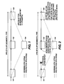
- FIG. 1 shows, in simplified block diagram form, an arrangement of nodes, i.e., network elements, in a point-to-point ATM transmission arrangement for virtual path group 1+1 protection switching that is operating in a normal node, i.e., with no fault detected.
- nodes i.e., network elements
- M:N protection switching arrangement could also employ the invention.
- the invention can also be employed in a so-called ring or mesh configuration of nodes.
- a left to right direction of flow of the communications traffic is being employed.
- communications traffic can and does also flow in a right to left direction.
- node 101 is considered a source node
- node 102 is considered an intermediate node
- node 103 is considered a sink, i.e., destination, node.
- VPG normal working virtual path group
- PVPG protection virtual path group
- node 104 is an intermediate node in the protection path. It is noted that the communications traffic is supplied from node 101 to both the working VPG path and the PVPG path.
- the VPG 1+1 protection switching architecture in the normal operation mode is illustrated in FIG. 1.
- This architecture comprisings of a VPG Source node 101 a VPG Sink node 103 and an arbitrary number of VPG intermediate nodes 102 supporting the VPG.
- a set of N VP connection segments (105) are logically assigned to a working VPG and a protection VPG.
- the VPG working and protection VPG assignments are handled by a sub-network management system. These assignments are specifically performed at the VPG Source and Sink nodes, 101 and 103, respectively.
- Intermediate nodes, i.e., 102 and 104, supporting the working VPG and the protection VPG, respectively, are not required to have knowledge of the VP connection segment logical assignment. Only proper VPI translation is required at intermediate nodes 102 and 104.
- the route and bandwidth of the protection VPG is preallocated by the sub-network management system.
- VPG Source node 101 the VP connection segments logically assigned to the VPG are 1:2 multicast onto the working VPG and the protection VPG. That is , the source signals on the working channel are copied identically onto the protection channel, which is characteristically done in 1+1 protection switching architectures.
- VPG Sink node 103 a VPG 2:1 selector is implemented to select the ingress connection traffic from the working VPG or the protection VPG. In the normal operation mode, the VPG selector is set to select the working VPG.
- FIG. 2 shows, in simplified block diagram form, a point-to-point ATM node arrangement illustrating a fault condition. For purposes of illustration, a physical layer defect is shown to have occurred between nodes 101 and 102.
- the VPG 1+1 protection switching architecture in the protection mode is illustrated in FIG. 2. The detailed functions of the VPG nodes 101, 102, 103, and 104 are described below. An overview of the VPG 1+1 protection switching actions is given as follows:
- the invention is equally applicable to M:N protection switching.
- the VPG 1+1 protection switching architecture described above is extendible to other protection switching architectures in which the protection channel bandwidth is not reserved and may be shared by several working connections.
- M protection connections serve N working connections.
- the VPG protection switching capability applies to the M:N arrangement, by changing protection switch in the protection switching technique with request for a protection switch, as selection from the working to the protection VPG is coordinated at both the source and the sink nodes.
- VPG_w and VPG_p are assigned at source node 101 and sink node 103 by a sub-network management system for a given set of one or more VP connections.
- the VPG may also be a set of VP connection segments, but it may not include VP connections and connection segments simultaneously.
- the set of VP connections or connection segments have common source and sink nodes and route between source and sink nodes 101 and 103, respectively.
- VPGs are not explicitly indicated in the ATM cell header, but instead, are logically associated with the VPI address tables that are maintained at source node 101 and sink node 103 via the network element (NE) controller (described below).
- Intermediate nodes 102 and 104 supporting the VP connections or connection segments are configured by a sub-network management system for providing VP working and protection connection routing, respectively, and OAM processing. Intermediate nodes do not need to have knowledge of the VPGs logical addressing.
- the VPG logical relationship to the TP address table 301, VPI address table 302 and VCI address table 303 is illustrated in FIG. 3.
- FIG. 4 illustrates a format of an ATM Operations and Maintenance (OAM) fault management cell including a defect type indicator which is also useful in describing the operation of the invention.
- the overall operation of the VPG protection switching method is described in terms of the following functions: defect detection, notification, and protection switching.
- the VPG protection switching method may be applied to VP connection and VP connection segment levels.
- two detection criteria of the defects are used in the ATM transmission networks: physical layer (server layer) defects and ATM layer (client layer) defects.
- the VP Alarm Indication Signal OAM cells VP-AIS
- ITU-T Recommendation I.610 noted above, are used to indicate defected VP connections.
- the VP-AIS function is used at the VP connection level for initiating VPG protection switching.
- VP-AIS cells are generated within at least 10 milliseconds following detection of the physical layer defect and sent downstream on all affected active VP connections from the VP connecting point node (e.g., ATM-XC/ADM) which detects the defect.
- the VP-AIS is then detected at the VP connection endpoint node, where VPG protection switching is then initiated.
- a hold-off timer may be enabled to delay VPG protection switching actions.
- a VP-AIS reception counter may be enabled to confirm the persistence of the VP-AIS before initiating VPG protection switching.
- a VP segment AIS For VPG protection switching at the VP segment level, a VP segment AIS is not defined in standards, but similar end-to-end VP-AIS operations principles are applied to define a segment level indication (VPseg-AIS) for initiating VPG protection switching.
- VPseg-AIS cells are generated within 10 milliseconds following detection of the physical layer defect and sent downstream on all affected active VP segments from the VP connecting point node(contained within the VP segment) which detects the defect. The VPseg-AIS is then detected at the VP connection segment endpoint node, where VPG protection switching is then initiated.
- a hold-off timer or VPseg-AIS reception counter may be enabled.
- the VP-AIS generation is suppressed and VPseg-AIS (described above) is generated within 10 milliseconds and sent downstream on all affected active VP segments.
- the VPseg-AIS is escalated to VP-AIS for the given VPI. The VP-AIS is then sent downstream to the VP connection endpoint node, where VPG protection switching is then initiated.
- a hold-off timer may be desired in this case to allow for any VPG protection switching enabled at the VP segment level to perform.
- indications are generated within 10 milliseconds following detection of the VP Loss of Continuity or degraded VP connection performance at the sink node for each affected VP connection or connection segment and sent to the sink node controller.
- VP-AIS generation is generated within 10 milliseconds at the VP segment end-point for the all affected VP segments. The VP-AIS is then sent downstream to the VP connection endpoint nodes, where VPG protection switching is then initiated.
- a hold-off timer may be desired again in this case to allow for any VPG protection switching enabled at the VP segment level to perform.
- the same VPI value as that of the affected VP is assigned to the VPseg-AIS cell.
- the VCI is used to distinguish VP connection level and connection segment level AIS cells.
- a Defect Type Indicator (DTI) is set to "0" for physical layer defect and "1" for an ATM layer defect.
- the structure and coding of the ATM OAM Fault Management Cell with the DTI is illustrated in FIG. 4.
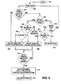
- FIG. 5 is a flow chart illustrating the VPG protection switching algorithm employed in an embodiment of the invention.
- the VPG protection switching algorithm may be applied to both the VP connection and connection segment levels.
- the VPG protection switching algorithm can be applied to both 1+1 and M:N protection switching architectures.
- the detection and notification mechanisms are exactly the same for both architectures.
- a sink TP node will perform protection switching in the 1+1 protection switching architecture.
- a source TP node will perform protection switching in the M:N protection switching architecture, where the sink TP node sends a switch request message to the source TP node when it receives a notification of a failure.
- the algorithm differentiates the 1+1 and M:N protection switching by "Switch/Switch Request".
- the VG protection switching sink TP algorithm is given below and the corresponding flow chart is illustrated in FIG. 5.
- step 501 The protection switching algorithm is begun in start step 501. Thereafter, control is transferred to the normal mode of operation step 502, as described above. Thereafter, control is transferred to detect TP defect at the TP sink node in step 503. If the test result in step 503 is yes, control is transferred to step 504 which initiates the holdoff timer start for physical layer protection. If the test result in step 503 is no, control is transferred to step 505 which tests the VP_ASI at the TP sink node. If the test result in step 505 is yes, control is transferred to step 506 which tests to determine if the VPI belongs to VPG_w. If the test result in step 506 is no, the test is essentially ended because step 507 indicates that the VPG is not protected.
- step 506 determines if the DTI is 0 or 1. If the test result in step 507 indicates 0, control is transferred to step 504. If the test result in step 508 is indicates 1, control is transferred to step 509 which initiates a holdoff timer for the ATM layer protection. Returning to step 505, if the test result is no, control is transferred to step 510 which detects the VP LOC at the TP sink node. If the test result is no in step 510, control is returned to step 502 and the process is iterated. If the test result in test 510 is yes, control is transferred to step 511 which tests whether the VPI belongs to VPG_w.
- step 511 If the test result in step 511 is no, control is transferred to step 512 which indicates that the VPG is not protected. If the test result in step 511 is yes, control is transferred to step 509. Upon either of holdoff timers in step 504 and 509 timing out, control is transferred to step 513 which detects, persists, holdoff timer expired, and VPG_p is available. If the test result in step 513 is no, step 513 continues to test as indicated above until a yes result is obtained. Upon a yes result in step 513, control is transferred to step 514 which effects a protection switch for all defected VPGs contained in the TP sink node. Thereafter, control is transferred to step 515 which indicates that the network is in the protection switching mode.
- the VG protection switching architectures and VG network element functionality is described, for simplicity, for ATM Virtual Path connection segments.
- the VG protection switching architectures and network element functionality is easily extensible to ATM Virtual Path connections.
- VPG Network Element Functional Architecture For Source Node 101, Intermediate Nodes 102 and 104 and Sink Node 103
- VPG Source, Intermediate, and Sink nodes 101, 102, 104 and 103, respectively, is illustrated, in a simplified block diagram, in FIG. 6.
- the VPG node includes of:
- the Line Termination functions are illustrated, in simplified block diagram, in FIG. 7.
- the LT functions are common to any VPG Source, Intermediate, or Sink nodes.
- the LT provides line termination functionality and physical layer defect detection.
- the O/E Converter (701) provides optical-to-electrical conversion of received SONET optical signals (e.g. OC-3) carrying ATM. (This step in not necessary for received electrical signals (e.g. DS3) carrying ATM).
- the electrical signal is transmitted to a SONET Framer and Section/Line Overhead Processor (702).
- the SONET Path Overhead and payload of the SONET frame, which carries the ATM cell stream, is transmitted to the Transmission Path (TP) Adaptation Processor (703).
- TP Transmission Path
- the ATM cell stream is extracted from the SONET frame and the cell stream is delineated into ATM cells.
- a Defect Detector (704) is necessary to detect Physical Layer defects. For example, Loss of Signal (LOS) is detected at the O/E Converter (701), Loss of Frame (LOF) is detected at the SONET Framer (702), and Loss of Cell Delineation (LCD) is detected at the TP Adaptation Processor (703). Detection criteria for these defects are according to specified standards. Indications of detected defects are sent to the node Controller (705). The node Controller also provides any required input to/output from the processors in the LT.
- LOS Loss of Signal
- LPF Loss of Frame
- LCD Loss of Cell Delineation
- the reverse set of functions are performed.
- TP Adaptation Processor (706) a received delineated ATM cell stream from the Fabric Interface is mapped to a SONET payload with SONET Path Overhead added.
- SONET Path/Payload stream is then framed with SONET Line and Section Overhead added at the SONET Overhead Insertion Processor (707).
- This electrical signal is then converted to an optical one at the E/O Converter (708) on output from the node. All of the LT external signal formats and required overhead processing is according to standards.
- the Switch Fabric Interface functions at a VPG Source node are illustrated, in simplified block diagram, in FIG. 8.
- the SFI provides ATM VP cell header processing and de/multiplexing, VP OAM cell processing, and cell addressing for input and routing to the Switch Fabric.
- ATM VP cell header processing and demultiplexing is performed at the ATM Cell Demux (801) according to standards.
- the demultiplexed VP connections, based on VPI, are transmitted to Segment OAM Cell Insertion Processors (802-i - 802-k). This processor is the generation point of OAM cells for activated VPIs.
- VP-AIS cells are inserted for each affected VP in the case where a TP defect is detected at the receiver LT.
- the LT defect indication to the SFI is handled by the SFI Controller interface (803).
- the Controller may also initiate other Segment OAM cell insertions at (802s) for selected VPIs. These insertions are related to provisioned functions for the VP connection segment, such as Continuity Check and Segment Performance Monitoring. These functions are needed to detect respectively Loss of Continuity and VP Segment Degrade defects, which may be used to initiate VPG protection switching.
- Continuity Check and Performance Monitoring OAM cells is according to I.610 standards.
- VP segment OAM cells are extracted at the Extraction Processors (804-l - 804-n).
- specific OAM cells requesting switch would be processed at (804s).
- the activated VPI streams are multiplexed at (805) for input to the LT transmitter.
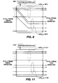
- the Switch Fabric (SF) logical configuration is illustrated, in simplified form, in FIG. 9.
- the individual VPIs are checked for a working VPG (901) association. This check is provided by memory table lockups, or via exchange information from the Controller (902).
- the ATM cells associated with this VPI are copied (903) onto the assigned VPI associated with the protection VPG.
- the working and protection VPI/VPG assignments were made initially by the sub-network management system.
- the ATM SF architecture is independent of the VPG protection switching method and no particular architecture (e.g. Shared Memory Fabric, Banyan, etc.) is required or implied. Only the mechanism to provide 1:2 cell copying is required.
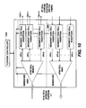
- the SFI functions at a VPG Intermediate node are illustrated, in simplified block diagram, in FIG. 10.
- the functions of this SFI are similar to the functions at the SFI at the Source node.
- Only VP segment OAM cell insertion (1001-i -1001-k) is needed to indicate the detection of a Physical Layer defect at the LT.
- the ingress side of the intermediate node is essentially identical to the egress side of the intermediate note which will not be described in detail.
- One VP segment AIS cell is inserted for each affected VPI and continues repeatedly until the initiating defect indication is cleared by the controller/element manager (1002) or the VP connection segment is released by the sub-network management system.
- the VP de/multiplexing functions and ATM cell header processing functions (1003) are the same as in the SFI Source node.
- the Switch Fabric logical configuration does not require any knowledge of the VPI/VPG association.
- the SF only requires proper VPI translation for the working and protection VPIs.
- the VPI translation is managed via the controller by the element manager.
- the Switch Fabric At the VPG Sink node, it is necessary for the Switch Fabric to have knowledge of the VPI/VPG logical association for proper routing to the egress SFI at the VPG Sink node.
- the SF logical configuration t the VPG Sink node is illustrated FIG. 11.
- the working VPG (1101) and the protection VPG (1102) are routed to the same egress SFI.
- the VPI/VPG association is managed by the Controller/Element Manager (1103).
- VP segment OAM cells are extracted and processed at extraction units (1201-l - 1201-n) for all activated VPI cell flows out of the SF.
- extraction units (1201) is where VPseg-AIS, VP segment LOC, and VP segment signal degrade defects are detected.
- the DTI for the VPseg-AIS is also decoded at (1201s).
- VPG Selector 1202
- VPG timer timer
- VPG Selector 1202
- VPG timer timer
- VPG VPIs protection VPG VPIs for routing to the ATM VP Cell Mux (1203).
- the VPG protection switching algorithm illustrated above in FIG. 5 is implemented in (1201s) and (1202).
- the VP segments are protected on a group basis, thus reduced processing is required at the SFI egress side of the VPG Sink node.
- the VPI/VPG association is managed via the Controller/Element Manager (1204).
Landscapes
- Engineering & Computer Science (AREA)
- Computer Networks & Wireless Communication (AREA)
- Data Exchanges In Wide-Area Networks (AREA)
Applications Claiming Priority (2)
| Application Number | Priority Date | Filing Date | Title |
|---|---|---|---|
| US08/689,175 US5838924A (en) | 1996-08-06 | 1996-08-06 | Asynchronous transfer mode (ATM) connection protection switching apparatus and method |
| US689175 | 1996-08-06 |
Publications (2)
| Publication Number | Publication Date |
|---|---|
| EP0824292A2 true EP0824292A2 (de) | 1998-02-18 |
| EP0824292A3 EP0824292A3 (de) | 2000-10-18 |
Family
ID=24767347
Family Applications (1)
| Application Number | Title | Priority Date | Filing Date |
|---|---|---|---|
| EP97305699A Withdrawn EP0824292A3 (de) | 1996-08-06 | 1997-07-29 | Einrichtung und Verfahren zur ATM-Schutzumschaltung |
Country Status (4)
| Country | Link |
|---|---|
| US (1) | US5838924A (de) |
| EP (1) | EP0824292A3 (de) |
| JP (1) | JPH1084362A (de) |
| CA (1) | CA2207538C (de) |
Cited By (15)
| Publication number | Priority date | Publication date | Assignee | Title |
|---|---|---|---|---|
| WO2000076261A1 (en) * | 1999-06-03 | 2000-12-14 | Fujitsu Network Communications, Inc. | PROTECTION ARCHITECTURE FOR VIRTUAL CHANNEL CONNECTIONS (VCCs) IN A TELECOMMUNICATIONS NETWORK |
| EP0961521A3 (de) * | 1998-05-29 | 2001-01-10 | Lucent Technologies Inc. | Verfahren und Vorrichtung zum Schalten von Signalen mit einem eingebetteten Signalgruppen Zustand |
| EP1083711A3 (de) * | 1999-09-09 | 2003-04-16 | Nortel Networks Limited | Verfahren und Schaltungsanordnung zur ATM-Ersatzschaltung |
| EP1083710A3 (de) * | 1999-09-09 | 2003-05-02 | Nortel Networks Limited | Verfahren und Vorrichtung zur ATM Gruppe-Schutzumschaltung |
| US6560202B1 (en) | 1998-07-27 | 2003-05-06 | Lucent Technologies Inc. | Control architecture using a multi-layer embedded signal status protocol |
| WO2003096631A1 (de) * | 2002-05-08 | 2003-11-20 | Siemens Aktiengesellschaft | Verfahren zur unterstützung von ersatzschaltungen in mpls-netzen |
| WO2004025865A1 (en) * | 2002-09-10 | 2004-03-25 | Telefonaktiebolaget Lm Ericsson (Publ) | Systems for protection link supervision |
| US6822962B1 (en) * | 1999-11-29 | 2004-11-23 | Hitachi Telecom Technologies, Ltd. | Virtual connection switching method and ATM switch |
| EP1059751A3 (de) * | 1999-06-09 | 2005-01-26 | Hitachi, Ltd. | Kommunikationssvorrichtung und -system |
| EP1022926A3 (de) * | 1999-01-20 | 2005-07-13 | Fujitsu Limited | Netzwerksystem mit mehreren Netzen niedriger Ordnung und mit einem Netzen höherer Ordnung |
| US6920105B1 (en) | 2000-09-15 | 2005-07-19 | Ciena Corporation | Interface receive for communications among network elements |
| US6941486B1 (en) | 1998-07-14 | 2005-09-06 | Siemens Aktiengesellschaft | Method and device for optimizing the transmission safety and the defect tolerance in high-bit-rate data networks |
| US7054324B1 (en) * | 2000-09-15 | 2006-05-30 | Ciena Corporation | Interface transmitter for communications among network elements |
| US7590049B1 (en) * | 2003-10-09 | 2009-09-15 | Nortel Networks Limited | System and method for configuring a network element to support protection switching in an optical network |
| US8116196B2 (en) * | 2002-01-31 | 2012-02-14 | Ciena Corporation | Shared mesh signaling method and apparatus |
Families Citing this family (78)
| Publication number | Priority date | Publication date | Assignee | Title |
|---|---|---|---|---|
| JP3008850B2 (ja) * | 1996-06-11 | 2000-02-14 | 日本電気株式会社 | ネットワークサーバの冗長構成方式 |
| US6256292B1 (en) * | 1996-07-11 | 2001-07-03 | Nortel Networks Corporation | Self-healing line switched ring for ATM traffic |
| JPH1056493A (ja) * | 1996-08-13 | 1998-02-24 | Nec Corp | 通信ネットワーク内における制御情報の転送装置 |
| JP3581765B2 (ja) * | 1996-09-20 | 2004-10-27 | 株式会社日立コミュニケーションテクノロジー | 複合リング形ネットワークシステムにおけるパス切替方法及び装置 |
| US6049523A (en) * | 1997-05-30 | 2000-04-11 | Lucent Technologies Inc. | System and method for achieving efficient coordination of protection switching |
| JPH10336195A (ja) * | 1997-06-02 | 1998-12-18 | Nec Corp | 選択的vp端切替方式 |
| US6324161B1 (en) * | 1997-08-27 | 2001-11-27 | Alcatel Usa Sourcing, L.P. | Multiple network configuration with local and remote network redundancy by dual media redirect |
| US6262820B1 (en) * | 1998-07-15 | 2001-07-17 | Lucent Technologies Inc. | Optical transmission system including optical restoration |
| JP3036524B2 (ja) * | 1998-08-14 | 2000-04-24 | 日本電気株式会社 | Vpプロテクションシステム及び方法 |
| US6856627B2 (en) | 1999-01-15 | 2005-02-15 | Cisco Technology, Inc. | Method for routing information over a network |
| US6876660B1 (en) * | 1999-02-16 | 2005-04-05 | Cisco Technology, Inc. | Method for implementing automatic protection switching (APS) using cell replication |
| JP3350926B2 (ja) * | 1999-03-30 | 2002-11-25 | 日本電気株式会社 | Ponのプロテクション切り換え方法および装置 |
| EP1056309B1 (de) * | 1999-05-28 | 2007-11-28 | Nokia Siemens Networks Oy | ATM Netzelement und Verfahren zur automatischen Schutzumschaltung einer Verbindung in einem "transmission convergence" Unterschichtteilnetz |
| US6477167B1 (en) | 1999-06-03 | 2002-11-05 | Fujitsu Network Communications, Inc. | Method and system for allocating bandwith to real-time variable bit rate (rt-VBR) traffic |
| US6442164B1 (en) | 1999-06-03 | 2002-08-27 | Fujitsu Network Communications, Inc. | Method and system for allocating bandwidth and buffer resources to constant bit rate (CBR) traffic |
| US6631406B1 (en) | 1999-06-03 | 2003-10-07 | Fujitsu Network Communications, Inc. | Common management information base (MIB) |
| US6760332B1 (en) | 1999-06-03 | 2004-07-06 | Fujitsu Network Communications, Inc. | ATM multicasting system and method |
| US6359565B1 (en) | 1999-06-03 | 2002-03-19 | Fujitsu Network Communications, Inc. | Method and system for monitoring the thermal status of a card shelf |
| WO2000076152A1 (en) * | 1999-06-03 | 2000-12-14 | Fujitsu Network Communications, Inc. | Method and system for transmitting traffic in a virtual tunnel of a transmission line |
| US6891836B1 (en) | 1999-06-03 | 2005-05-10 | Fujitsu Network Communications, Inc. | Switching complex architecture and operation |
| US6317426B1 (en) | 1999-06-03 | 2001-11-13 | Fujitsu Network Communications, Inc. | Method and apparatus for hybrid protection in a switching network |
| US6498792B1 (en) | 1999-06-03 | 2002-12-24 | Fujitsu Network Communications, Inc. | Method and apparatus for switching signals of multiple different communication protocols |
| US6665301B1 (en) * | 1999-06-03 | 2003-12-16 | Fujitsu Network Communications, Inc. | Transmission slot allocation method and map for virtual tunnels in a transmission line |
| US6396847B1 (en) | 1999-06-03 | 2002-05-28 | Fujitsu Networks Communications, Inc. | Dialable data services/TDM bandwidth management |
| US6658006B1 (en) | 1999-06-03 | 2003-12-02 | Fujitsu Network Communications, Inc. | System and method for communicating data using modified header bits to identify a port |
| US6330168B1 (en) | 1999-06-03 | 2001-12-11 | Fujitsu Networks Communications, Inc. | Card shelf cable management system and method |
| US6501758B1 (en) | 1999-06-03 | 2002-12-31 | Fujitsu Network Communications, Inc. | Hybrid ATM/TDM transport over a common fiber ring |
| US6785285B1 (en) | 1999-06-03 | 2004-08-31 | Fujitsu Network Communications, Inc. | Method and system for providing broadcast channels over an emulated subnetwork |
| US6674751B1 (en) | 1999-06-03 | 2004-01-06 | Fujitsu Network Communications, Inc. | Serialized bus communication and control architecture |
| US6356444B1 (en) | 1999-06-03 | 2002-03-12 | Fujitsu Network Communications, Inc. | Card shelf heat transfer system and method |
| US7136350B1 (en) * | 1999-07-12 | 2006-11-14 | Lucent Technologies Inc. | Efficient support for VP/VC groups |
| AU7078500A (en) * | 1999-09-14 | 2001-04-17 | Megaxess, Inc. | Method and apparatus for prevention of congestion in atm networks through atm protection switching |
| US6895024B1 (en) * | 1999-10-12 | 2005-05-17 | Marconi Communications, Inc. | Efficient implementation of 1+1 port redundancy through the use of ATM multicast |
| US7298693B1 (en) | 1999-10-21 | 2007-11-20 | Tellabs Operations, Inc. | Reverse notification tree for data networks |
| US7315510B1 (en) | 1999-10-21 | 2008-01-01 | Tellabs Operations, Inc. | Method and apparatus for detecting MPLS network failures |
| AU1098101A (en) * | 1999-10-21 | 2001-04-30 | Tellabs Operations, Inc. | Method for establishing an mpls data network protection pathway |
| US7804767B1 (en) | 1999-10-25 | 2010-09-28 | Tellabs Operations, Inc. | Protection/restoration of MPLS networks |
| GB9926884D0 (en) * | 1999-11-12 | 2000-01-12 | Agilent Technologies Inc | ATM service disruption measurement |
| US6850483B1 (en) * | 1999-11-30 | 2005-02-01 | Ciena Corporation | Method and system for protecting frame relay traffic over SONET rings |
| US6865183B1 (en) * | 1999-12-17 | 2005-03-08 | Pmc-Sierra, Inc. | F5-to-F4 OAM alarm notification and cell generation in multiple connection ATM switches |
| AU2001230971A1 (en) * | 2000-01-20 | 2001-07-31 | Megaxess, Inc. | Address translation table for fast atm protection switching |
| US6323974B1 (en) * | 2000-01-25 | 2001-11-27 | Corning Incorporated | Optical protection system for liquid crystal switches |
| US7463581B1 (en) * | 2000-02-07 | 2008-12-09 | Cisco Technology, Inc. | Re-routing connections using redundant path connections and loopbacks |
| EP1126742A1 (de) * | 2000-02-15 | 2001-08-22 | Siemens Aktiengesellschaft | Verfahren zum Ersatzschalten von Übertragungseinrichtungen in MPLS-Netzen |
| US7161944B1 (en) * | 2000-05-31 | 2007-01-09 | Cisco Technology, Inc. | Method and system for optimized routing and protection of VT traffic in SONET networks |
| US6847607B1 (en) * | 2000-06-01 | 2005-01-25 | Sirocco Systems, Inc. | Automatic provisioning of protection circuits in a communications network |
| US6829215B2 (en) * | 2000-10-31 | 2004-12-07 | Marconi Intellectual Property (Ringfence) Inc. | IP multi-homing |
| US8428056B2 (en) * | 2000-12-22 | 2013-04-23 | Avaya, Inc. | Generation of redundant scheduled network paths using a branch and merge technique |
| US20020159392A1 (en) * | 2001-04-25 | 2002-10-31 | Adc Telecommunications Israel Ltd. | Simplified ATM ring protection for access networks |
| US7477594B2 (en) * | 2001-05-16 | 2009-01-13 | Cisco Technology, Inc. | Method for restoring a virtual path in an optical network using 1:N protection |
| US6580731B1 (en) | 2001-05-18 | 2003-06-17 | Network Elements, Inc. | Multi-stage SONET overhead processing |
| US7002967B2 (en) | 2001-05-18 | 2006-02-21 | Denton I Claude | Multi-protocol networking processor with data traffic support spanning local, regional and wide area networks |
| US6952395B1 (en) * | 2001-06-01 | 2005-10-04 | Calix Networks, Inc. | Optical network restoration |
| US7292528B2 (en) * | 2001-06-04 | 2007-11-06 | Turin Networks | Method and apparatus to facilitate independent protection switching in a distributed network |
| US7035294B2 (en) * | 2001-06-04 | 2006-04-25 | Calix Networks, Inc. | Backplane bus |
| US7006497B2 (en) * | 2001-06-04 | 2006-02-28 | Calix Networks, Inc. | Traffic merging system |
| US7075953B2 (en) * | 2001-07-30 | 2006-07-11 | Network-Elements, Inc. | Programmable SONET framing |
| US7289428B2 (en) * | 2001-08-13 | 2007-10-30 | Tellabs Operations, Inc. | Inter-working mesh telecommunications networks |
| US20080002669A1 (en) * | 2001-09-14 | 2008-01-03 | O'brien Ray | Packet voice gateway |
| US7039005B2 (en) | 2001-10-02 | 2006-05-02 | Fujitsu Limited | Protection switching in a communications network employing label switching |
| US6766482B1 (en) | 2001-10-31 | 2004-07-20 | Extreme Networks | Ethernet automatic protection switching |
| EP1318632B1 (de) * | 2001-11-24 | 2007-01-03 | Lg Electronics Inc. | Steuerungsverfahren für Paketdatenübertragung |
| KR100428762B1 (ko) * | 2001-11-29 | 2004-04-28 | 삼성전자주식회사 | 링 구조의 비동기전송모드 전송시스템에서의 보호절체방법 |
| US7065041B2 (en) * | 2001-12-14 | 2006-06-20 | Siemens Communications, Inc. | Method for resilient call setup through ATM networks for Softswitch applications |
| US7206281B2 (en) * | 2002-05-03 | 2007-04-17 | Ciena Corporation | Calculating physical routes in a communication network |
| US7197008B1 (en) | 2002-07-05 | 2007-03-27 | Atrica Israel Ltd. | End-to-end notification of local protection using OAM protocol |
| US7436763B1 (en) * | 2002-07-31 | 2008-10-14 | Nortel Networks Limited | Data communication apparatus with a dual mode protection switching system |
| KR100507806B1 (ko) * | 2003-01-29 | 2005-08-17 | 삼성전자주식회사 | 링구조 비동기전송 모드방식의 시스템에 있어서 노드그룹을 이용한 보호 절체 장치 및 그 방법 |
| GB0315745D0 (en) * | 2003-07-04 | 2003-08-13 | Novartis Ag | Organic compounds |
| US7697417B2 (en) * | 2003-07-18 | 2010-04-13 | Alcatel-Lucent Usa Inc. | Methods and devices for re-routing MPLS traffic |
| US8554947B1 (en) * | 2003-09-15 | 2013-10-08 | Verizon Laboratories Inc. | Network data transmission systems and methods |
| US7602698B2 (en) * | 2004-03-02 | 2009-10-13 | Tellabs Operations, Inc. | Systems and methods for providing multi-layer protection switching within a sub-networking connection |
| US7536101B1 (en) * | 2004-08-02 | 2009-05-19 | Sprint Communications Company Lp | Communication system with cost based protection |
| CN100334857C (zh) * | 2004-09-27 | 2007-08-29 | 华为技术有限公司 | 一种环网及其业务实现方法 |
| ITMI20042490A1 (it) * | 2004-12-23 | 2005-03-23 | Marconi Comm Spa | Sistema di protezione atm |
| US8542574B2 (en) * | 2005-06-29 | 2013-09-24 | Honeywell International Inc. | Apparatus and method for network error prevention |
| US20080281987A1 (en) * | 2007-05-10 | 2008-11-13 | Nortel Networks Limited | Facilitating automatic protection switching for provider backbone network |
| CA3216038A1 (en) * | 2021-10-26 | 2023-05-04 | Ciena Corporation | Fast optical receiver recovery on client side using optical interconnects with dsps |
Family Cites Families (1)
| Publication number | Priority date | Publication date | Assignee | Title |
|---|---|---|---|---|
| JPH0744542B2 (ja) * | 1993-01-11 | 1995-05-15 | 日本電気株式会社 | 非同期転送モードにおける仮想パスの帯域割当方式 |
-
1996
- 1996-08-06 US US08/689,175 patent/US5838924A/en not_active Expired - Lifetime
-
1997
- 1997-06-11 CA CA002207538A patent/CA2207538C/en not_active Expired - Fee Related
- 1997-07-29 EP EP97305699A patent/EP0824292A3/de not_active Withdrawn
- 1997-07-31 JP JP20667097A patent/JPH1084362A/ja active Pending
Non-Patent Citations (2)
| Title |
|---|
| HIROYUKI FUJII ET AL: "RESTORATION MESSAGE TRANSFER MECHANISM AND RESTORATION CHARACTERISTICS OF DOUBLE-SEARCH SELF-HEALING ATM NETWORK" IEEE JOURNAL ON SELECTED AREAS IN COMMUNICATIONS,US,IEEE INC. NEW YORK, vol. 12, no. 1, 1994, pages 149-157, XP000493896 ISSN: 0733-8716 * |
| MUN CHOON CHAN ET AL: "AN ARCHITECTURE FOR BROADBAND VIRTUAL NETWORKS UNDER CUSTOMER CONTROL" IEEE NETWORK OPERATIONS AND MANAGEMENT SYMPOSIUM (NOMS),US,NEW YORK, IEEE, vol. SYMP. 5, 15 April 1996 (1996-04-15), pages 135-144, XP000641086 ISBN: 0-7803-2519-2 * |
Cited By (20)
| Publication number | Priority date | Publication date | Assignee | Title |
|---|---|---|---|---|
| EP0961521A3 (de) * | 1998-05-29 | 2001-01-10 | Lucent Technologies Inc. | Verfahren und Vorrichtung zum Schalten von Signalen mit einem eingebetteten Signalgruppen Zustand |
| US6301228B1 (en) | 1998-05-29 | 2001-10-09 | Lucent Technologies, Inc. | Method and apparatus for switching signals using an embedded group signal status |
| AU745963B2 (en) * | 1998-05-29 | 2002-04-11 | Lucent Technologies Inc. | A method and apparatus for switching signals using an embedded group signal status |
| US6941486B1 (en) | 1998-07-14 | 2005-09-06 | Siemens Aktiengesellschaft | Method and device for optimizing the transmission safety and the defect tolerance in high-bit-rate data networks |
| US6560202B1 (en) | 1998-07-27 | 2003-05-06 | Lucent Technologies Inc. | Control architecture using a multi-layer embedded signal status protocol |
| EP1022926A3 (de) * | 1999-01-20 | 2005-07-13 | Fujitsu Limited | Netzwerksystem mit mehreren Netzen niedriger Ordnung und mit einem Netzen höherer Ordnung |
| WO2000076261A1 (en) * | 1999-06-03 | 2000-12-14 | Fujitsu Network Communications, Inc. | PROTECTION ARCHITECTURE FOR VIRTUAL CHANNEL CONNECTIONS (VCCs) IN A TELECOMMUNICATIONS NETWORK |
| US6353593B1 (en) | 1999-06-03 | 2002-03-05 | Fujitsu Network Communications, Inc. | Protection architecture for virtual channel connections (VCCS) in a telecommunications network |
| EP1059751A3 (de) * | 1999-06-09 | 2005-01-26 | Hitachi, Ltd. | Kommunikationssvorrichtung und -system |
| EP1083710A3 (de) * | 1999-09-09 | 2003-05-02 | Nortel Networks Limited | Verfahren und Vorrichtung zur ATM Gruppe-Schutzumschaltung |
| US6654923B1 (en) | 1999-09-09 | 2003-11-25 | Nortel Networks Limited | ATM group protection switching method and apparatus |
| EP1083711A3 (de) * | 1999-09-09 | 2003-04-16 | Nortel Networks Limited | Verfahren und Schaltungsanordnung zur ATM-Ersatzschaltung |
| US6898177B1 (en) | 1999-09-09 | 2005-05-24 | Nortel Networks Limited | ATM protection switching method and apparatus |
| US6822962B1 (en) * | 1999-11-29 | 2004-11-23 | Hitachi Telecom Technologies, Ltd. | Virtual connection switching method and ATM switch |
| US6920105B1 (en) | 2000-09-15 | 2005-07-19 | Ciena Corporation | Interface receive for communications among network elements |
| US7054324B1 (en) * | 2000-09-15 | 2006-05-30 | Ciena Corporation | Interface transmitter for communications among network elements |
| US8116196B2 (en) * | 2002-01-31 | 2012-02-14 | Ciena Corporation | Shared mesh signaling method and apparatus |
| WO2003096631A1 (de) * | 2002-05-08 | 2003-11-20 | Siemens Aktiengesellschaft | Verfahren zur unterstützung von ersatzschaltungen in mpls-netzen |
| WO2004025865A1 (en) * | 2002-09-10 | 2004-03-25 | Telefonaktiebolaget Lm Ericsson (Publ) | Systems for protection link supervision |
| US7590049B1 (en) * | 2003-10-09 | 2009-09-15 | Nortel Networks Limited | System and method for configuring a network element to support protection switching in an optical network |
Also Published As
| Publication number | Publication date |
|---|---|
| EP0824292A3 (de) | 2000-10-18 |
| JPH1084362A (ja) | 1998-03-31 |
| CA2207538A1 (en) | 1998-02-06 |
| US5838924A (en) | 1998-11-17 |
| CA2207538C (en) | 2002-01-08 |
Similar Documents
| Publication | Publication Date | Title |
|---|---|---|
| CA2207538C (en) | Asynchronous transfer mode (atm) connection protection switching apparatus and method | |
| US5793745A (en) | Bundled protection switching in a wide area network background of the invention | |
| US6301254B1 (en) | Virtual path ring protection method and apparatus | |
| JP3371948B2 (ja) | 情報通信方法およびsonet回線交換リング用ノード | |
| US6654923B1 (en) | ATM group protection switching method and apparatus | |
| US6147968A (en) | Method and apparatus for data transmission in synchronous optical networks | |
| US5636206A (en) | System for achieving alarm masking processing | |
| US7170852B1 (en) | Mesh with projection channel access (MPCA) | |
| US6021112A (en) | Path switching ring control apparatus in a synchronous (SDH) network that includes an asynchronous (PDH) subnetwork | |
| EP1010346A1 (de) | Erzeugung eines auslösesignals zum veranlassen einer schutzumschaltung | |
| JPH07202924A (ja) | 通信システム | |
| US20020114031A1 (en) | Ring configuration method, failure recovery method, and node address assignment method when configuring ring in network | |
| JPH07212382A (ja) | 通信システム | |
| EP1056309B1 (de) | ATM Netzelement und Verfahren zur automatischen Schutzumschaltung einer Verbindung in einem "transmission convergence" Unterschichtteilnetz | |
| Kajiyama et al. | An ATM VP-based self-healing ring | |
| JPH07264229A (ja) | 仮想リング構成システム | |
| Veitch et al. | ATM network resilience | |
| JP4565751B2 (ja) | 伝送装置 | |
| US6898177B1 (en) | ATM protection switching method and apparatus | |
| US20030142678A1 (en) | Virtual path ring protection method and apparatus | |
| KR100298968B1 (ko) | 링 전송시스템의 일반화된 결정성 스퀠칭 | |
| GB2321571A (en) | Network/node interface | |
| Anderson et al. | Virtual path group protection switching—A method for fast ATM network survivability | |
| JP3151768B2 (ja) | 同期・非同期転送モード対応型セルフヒーリング・リング方式 | |
| JP2822964B2 (ja) | リングシステム |
Legal Events
| Date | Code | Title | Description |
|---|---|---|---|
| PUAI | Public reference made under article 153(3) epc to a published international application that has entered the european phase |
Free format text: ORIGINAL CODE: 0009012 |
|
| AK | Designated contracting states |
Kind code of ref document: A2 Designated state(s): DE FR GB SE |
|
| AX | Request for extension of the european patent |
Free format text: AL;LT;LV;RO;SI |
|
| PUAL | Search report despatched |
Free format text: ORIGINAL CODE: 0009013 |
|
| AK | Designated contracting states |
Kind code of ref document: A3 Designated state(s): AT BE CH DE DK ES FI FR GB GR IE IT LI LU MC NL PT SE |
|
| AX | Request for extension of the european patent |
Free format text: AL;LT;LV;RO;SI |
|
| 17P | Request for examination filed |
Effective date: 20010405 |
|
| AKX | Designation fees paid |
Free format text: DE FR GB SE |
|
| STAA | Information on the status of an ep patent application or granted ep patent |
Free format text: STATUS: THE APPLICATION HAS BEEN WITHDRAWN |
|
| 18W | Application withdrawn |
Effective date: 20060725 |