EP0824432B1 - Verfahren zum betrieb eines pneumatischen bremskraftverstärkers - Google Patents
Verfahren zum betrieb eines pneumatischen bremskraftverstärkers Download PDFInfo
- Publication number
- EP0824432B1 EP0824432B1 EP97914179A EP97914179A EP0824432B1 EP 0824432 B1 EP0824432 B1 EP 0824432B1 EP 97914179 A EP97914179 A EP 97914179A EP 97914179 A EP97914179 A EP 97914179A EP 0824432 B1 EP0824432 B1 EP 0824432B1
- Authority
- EP
- European Patent Office
- Prior art keywords
- value
- controller
- control
- solenoid
- pressure
- Prior art date
- Legal status (The legal status is an assumption and is not a legal conclusion. Google has not performed a legal analysis and makes no representation as to the accuracy of the status listed.)
- Expired - Lifetime
Links
- 238000000034 method Methods 0.000 title claims description 17
- 230000005540 biological transmission Effects 0.000 claims description 12
- 238000007789 sealing Methods 0.000 claims description 8
- 241000209035 Ilex Species 0.000 description 1
- 238000011161 development Methods 0.000 description 1
- 230000018109 developmental process Effects 0.000 description 1
- 238000011144 upstream manufacturing Methods 0.000 description 1
Images



Classifications
-
- B—PERFORMING OPERATIONS; TRANSPORTING
- B60—VEHICLES IN GENERAL
- B60T—VEHICLE BRAKE CONTROL SYSTEMS OR PARTS THEREOF; BRAKE CONTROL SYSTEMS OR PARTS THEREOF, IN GENERAL; ARRANGEMENT OF BRAKING ELEMENTS ON VEHICLES IN GENERAL; PORTABLE DEVICES FOR PREVENTING UNWANTED MOVEMENT OF VEHICLES; VEHICLE MODIFICATIONS TO FACILITATE COOLING OF BRAKES
- B60T13/00—Transmitting braking action from initiating means to ultimate brake actuator with power assistance or drive; Brake systems incorporating such transmitting means, e.g. air-pressure brake systems
- B60T13/10—Transmitting braking action from initiating means to ultimate brake actuator with power assistance or drive; Brake systems incorporating such transmitting means, e.g. air-pressure brake systems with fluid assistance, drive, or release
- B60T13/66—Electrical control in fluid-pressure brake systems
- B60T13/72—Electrical control in fluid-pressure brake systems in vacuum systems or vacuum booster units
-
- B—PERFORMING OPERATIONS; TRANSPORTING
- B60—VEHICLES IN GENERAL
- B60T—VEHICLE BRAKE CONTROL SYSTEMS OR PARTS THEREOF; BRAKE CONTROL SYSTEMS OR PARTS THEREOF, IN GENERAL; ARRANGEMENT OF BRAKING ELEMENTS ON VEHICLES IN GENERAL; PORTABLE DEVICES FOR PREVENTING UNWANTED MOVEMENT OF VEHICLES; VEHICLE MODIFICATIONS TO FACILITATE COOLING OF BRAKES
- B60T13/00—Transmitting braking action from initiating means to ultimate brake actuator with power assistance or drive; Brake systems incorporating such transmitting means, e.g. air-pressure brake systems
- B60T13/10—Transmitting braking action from initiating means to ultimate brake actuator with power assistance or drive; Brake systems incorporating such transmitting means, e.g. air-pressure brake systems with fluid assistance, drive, or release
- B60T13/66—Electrical control in fluid-pressure brake systems
- B60T13/662—Electrical control in fluid-pressure brake systems characterised by specified functions of the control system components
Definitions
- the invention relates to a method for operating a pneumatic brake booster according to the preamble of claim 1.
- This object is achieved in that the hydraulic pressure applied in the master brake cylinder determined and one together with a pressure command signal Pressure regulator is supplied, the output variable one Control current for the electromagnet corresponds and one Limiter is fed, which limits the desired Defines the control range and its output variable with the value of the current supplied to the electromagnet is compared and the comparison result is fed to a current regulator, which generates the voltage to be applied to the electromagnet.
- a second solution to the task set out above exists in that the entered in the master cylinder hydraulic pressure determined and after a comparison with a print command signal a non-linear Transmission link with upward and downward restrictions is supplied, which is followed by an amplifier, its output variable with the value of the electromagnet supplied current is compared and the comparison result a current controller is supplied, which to the Electromagnet generated voltage to be applied. It is advantageous if the output variable of the non-linear A feedforward value is added to the transmission element.
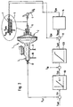
- the braking system for motor vehicles shown in the drawing this is particularly suitable for pressure control processes consists essentially of an actuating unit 1, an electronic regulator, in particular a pressure regulator 8 and wheel brakes, not shown.
- the operating unit 1 in turn consists of an actuating pedal 4 actuable pneumatic brake booster, preferably a vacuum brake booster 2, the one Master brake cylinder 3, preferably a tandem master cylinder, is connected downstream, the pressure rooms, not shown, above hydraulic lines 9, 10 with the wheel brakes in Connect.
- On the operating pedal 4 is one Actuating rod 5 coupled to the mechanical Actuation of a shown only schematically Control valve 6 is used to build and dismantle a pneumatic differential pressure in the housing of the vacuum brake booster 2 controls.
- An electromagnet 7 enables (external) actuation of the control valve 6 regardless of the operating rod 5.
- the External actuation is preferably carried out by means of a the armature of the electromagnet 7 cooperating, not shown sleeve, one of the sealing seats of the control valve 6 wears.
- An actual pressure P is generated from a device connected to the master brake cylinder 2, pressure sensor 17 is in a pressure regulator 8 connected upstream of comparison circuit 11 with a signal supplied from an unshown superordinate vehicle controller pressure setting signal P set so that a control deviation Dp is formed compared.
- the pressure regulator 8 is designed as a proportionally acting transmission element with constant gain K, the output signal I St of which is added in an addition circuit 16 to a pre-set control signal I 0 , the value of which defines the limits of the desired control range. With this measure, the gain K of the proportional pressure regulator 8 can be reduced or the pressure regulator 8 can be converted into a non-linear transmission element. This also increases the signal: noise ratio, so that the controllability is improved.
- the addition result ⁇ I is fed to a limiter 12, the output signal of which represents a current setpoint I soll , which is compared in a second comparison circuit 13 with the measured current value I EM supplied to the electromagnet 6.
- the comparison result I Regel is processed in a current regulator 14 connected downstream of the comparison circuit 13 to a signal value which represents the voltage U EM applied to the electromagnet 6.
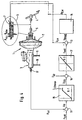
- the pressure regulator mentioned in connection with FIG. 1 is designed as a non-linear transmission element 80 with a downward limitation.
- the upper limit of the control range is provided by limiter 120, as in the example shown in FIG. 1.
- the pressure regulator mentioned in connection with FIG. 1 is designed as a non-linear transmission element 81 with an upper limit.
- the pilot control value I 20 to be added to the output variable I 2St of the pressure regulator 81 represents the upper limit value of the control range (by moving the characteristic curve of the pressure regulator 81 upwards on the vertical coordinate axis).
- the lower limit of the control range is provided by limiter 121, as in the example shown in FIG. 1.
- control deviation ⁇ p is finally fed to a non-linear transmission element 15 with limitation of the output variable upwards and downwards, which is effectively connected to a linear amplifier 17 with gain H.
Landscapes
- Engineering & Computer Science (AREA)
- Transportation (AREA)
- Mechanical Engineering (AREA)
- Braking Systems And Boosters (AREA)
- Regulating Braking Force (AREA)
Description
- Fig. 1
- eine erste Ausführung eines Bremssystems zur Durchführung des erfindungsgemäßen Verfahrens, stark vereinfacht;
- Fig. 2
- eine zweite Ausführung eines Bremssystems zur Durchführung des erfindungsgemäßen Verfahrens in einer der Fig.1 entsprechenden Darstellung,
- Fig. 3
- eine dritte Ausführung eines Bremssystems zur Durchführung des erfindungsgemäßen Verfahrens in einer der Fig.1 entsprechenden Darstellung,
- Fig. 4
- eine andere Ausführung eines Bremssystems zur Durchführung des erfindungsgemäßen Verfahrensnach Anspruch 6 in einer der Fig.1 entsprechenden Darstellung, und
- Fig. 5a, b und c
- Zeitverläufe des dem Elektromagneten zugeführten Stromes (Fig. 5a), des Betätigungsweges der das Steuerventil betätigenden Hülse bzw. des Ankers des Elektromagneten (Fig. 5b) und des bei einer Fremdbetätigung im Hauptbremszylinder eingesteuerten hydraulischen Druckes (Fig. 5c), jeweils bei zwei unterschiedlichen Werten eines die Grenzen des Regelbereichs beeinflussenden Stromkorrekturwertes.
I30 * H = unterer Grenzwert des Regelbereichs
(I3Stmax + I30) * H = oberer Grenzwert des Regelbereichs, wobei I3Stmax die obere Begrenzung des nicht linearen Druckreglers 80 darstellt.
Claims (7)
- Verfahren zum Betrieb eines pneumatischen Bremskraftverstärkers für Kraftfahrzeuge, der eine bewegliche Wand sowie ein eine auf die bewegliche Wand einwirkende pneumatische Druckdifferenz steuerndes Steuerventil (6) aufweist, das mindestens zwei Dichtsitze sowie einen mit den Dichtsitzen zusammenwirkenden elastischen Ventilkörper aufweist und einerseits durch den Fahrer mittels einer Betätigungsstange (5) und andererseits unabhängig vom Fahrerwillen durch einen mit einem der Dichtsitze in kraftübertragender Verbindung stehenden Elektromagneten (7) betätigbar ist, wobei dem Bremskraftverstärker (2) ein Hauptbremszylinder (3) nachgeschaltet ist, der mit den einzelnen Fahrzeugrädern zugeordneten Radbremsen in Verbindung steht, dadurch gekennzeichnet, daß der im Hauptbremszylinder (3) eingesteuerte hydraulische Druck (Pist)ermittelt und nach einem Vergleich mit einem Druckvorgabesignal (PSoll) einem Druckregler (8;80;81) zugeführt wird, dessen Ausgangsgröße einem Steuerstrom (ISt;I1St;I2St) für den Elektromagneten (7) entspricht und einem Begrenzer (12;120;121) zugeführt wird, der die Grenzwerte des gewünschten Regelbereichs festlegt und dessen Ausgangsgröße (ISoll) mit dem Wert (IEM) des dem Elektromagneten (7) zugeführten Stromes verglichen wird und das Vergleichsergebnis (IRegel) einem Stromregler (14) zugeführt wird, der die an den Elektromagneten (7) anzulegende Spannung (UEM) erzeugt.
- Verfahren nach Anspruch 1 dadurch gekennzeichnet, daß der Druckregler (8) als ein proportional wirkender Regler (P-Regler) ausgebildet ist.
- Verfahren nach Anspruch 1 oder 2 dadurch gekennzeichnet, daß zur Ausgangsgröße(ISt;I1St;I2St) des Druckreglers (8;80;81) ein Vorsteuerungswert (I0;I10;I20) hinzuaddiert wird, um die Reglerverstärkung zu reduzieren.
- Verfahren nach Anspruch 3 dadurch gekennzeichnet, daß der Druckregler als nichtlineares Übertragungsglied (80) ausgebildet ist, wobei der Vorsteuerungswert (I10) den unteren Grenzwert des Regelbereichs sicherstellt, dessen oberer Grenzwert vom Begrenzer (120) geliefert wird.
- Verfahren nach Anspruch 3 dadurch gekennzeichnet, daß der Druckregler als nichtlineares Übertragungsglied (81) ausgebildet ist, wobei der Vorsteuerungswert (I20) den oberen Grenzwert des Regelbereichs sicherstellt, dessen unterer Grenzwert vom Begrenzer (121) geliefert wird.
- Verfahren zum Betrieb eines pneumatischen Bremskraftverstärkers für Kraftfahrzeuge, der eine bewegliche wand sowie ein eine auf die bewegliche Wand einwirkende pneumatische Druckdifferenz steuerndes Steuerventil (6) aufweist, das mindestens zwei Dichtsitze sowie einen mit den Dichtsitzen zusammenwirkenden elastischen Ventilkörper aufweist und einerseits durch den Fahrer mittels einer Betätigungsstange (5) und andererseits unabhängig vom Fahrerwillen durch einen mit einem der Dichtsitze in kraftübertragender Verbindung stehenden Elektromagneten (7) betätigbar ist, wobei dem Bremskraftverstärker (2) ein Hauptbremszylinder (3) nachgeschaltet ist, der mit den einzelnen Fahrzeugrädern zugeordneten Radbremsen in Verbindung steht, dadurch gekennzeichnet, daß der im Hauptbremszylinder (3) eingesteuerte hydraulische Druck (Pist) ermittelt und nach einem Vergleich mit einem Druckvorgabesignal (PSoll) einem nichtlinearen Übertragungsglied (15) mit Beschränkung nach oben und unten zugeführt wird, dem ein Verstärker (17) nachgeschaltet ist, dessen Ausgangsgröße mit dem Wert des dem Elektromagneten (7) zugeführten Stromes (IEM) verglichen wird und das Vergleichsergebnis einem Stromregler (14) zugeführt wird, der die an den Elektromagneten (7) anzulegende Spannung (UEM) erzeugt.
- Verfahren nach Anspruch 6 dadurch gekennzeichnet, daß zur Ausgangsgröße (I3ST) des nichtlinearen Übertragungsglieds (15) ein Vorsteuerungswert (I30) hinzuaddiert wird.
Applications Claiming Priority (3)
| Application Number | Priority Date | Filing Date | Title |
|---|---|---|---|
| DE19609192A DE19609192A1 (de) | 1996-03-09 | 1996-03-09 | Verfahren zum Betrieb eines pneumatischen Bremskraftverstärkers |
| DE19609192 | 1996-03-09 | ||
| PCT/EP1997/000988 WO1997032768A1 (de) | 1996-03-09 | 1997-02-28 | Verfahren zum betrieb eines pneumatischen bremskraftverstärkers |
Publications (2)
| Publication Number | Publication Date |
|---|---|
| EP0824432A1 EP0824432A1 (de) | 1998-02-25 |
| EP0824432B1 true EP0824432B1 (de) | 2002-05-22 |
Family
ID=7787738
Family Applications (1)
| Application Number | Title | Priority Date | Filing Date |
|---|---|---|---|
| EP97914179A Expired - Lifetime EP0824432B1 (de) | 1996-03-09 | 1997-02-28 | Verfahren zum betrieb eines pneumatischen bremskraftverstärkers |
Country Status (10)
| Country | Link |
|---|---|
| US (1) | US6006648A (de) |
| EP (1) | EP0824432B1 (de) |
| JP (1) | JP4040681B2 (de) |
| AU (1) | AU2152997A (de) |
| CZ (1) | CZ289418B6 (de) |
| DE (2) | DE19609192A1 (de) |
| ES (1) | ES2174241T3 (de) |
| HU (1) | HU223444B1 (de) |
| PL (1) | PL183126B1 (de) |
| WO (1) | WO1997032768A1 (de) |
Families Citing this family (7)
| Publication number | Priority date | Publication date | Assignee | Title |
|---|---|---|---|---|
| DE19752868A1 (de) * | 1997-11-28 | 1999-06-10 | Lucas Ind Plc | Pneumatischer Bremskraftverstärker mit verringerter Ansprechkraft |
| DE19858649C1 (de) * | 1998-12-18 | 2000-06-15 | Lucas Ind Plc | Elektronisch steuerbarer Bremskraftverstärker |
| JP3700523B2 (ja) | 2000-02-25 | 2005-09-28 | 株式会社日立製作所 | 倍力装置の制御装置 |
| DE10151465B4 (de) * | 2000-10-19 | 2008-01-31 | Aisin Seiki K.K., Kariya | Fahrzeugbewegungssteuervorrichtung |
| JP3861609B2 (ja) * | 2001-02-28 | 2006-12-20 | 株式会社日立製作所 | ブレーキ倍力装置の制御装置 |
| US8128179B2 (en) | 2002-05-23 | 2012-03-06 | Continental Teves Ag & Co. Ohg | Method for operating an actuating unit for motor vehicle brakes |
| CN111959472A (zh) * | 2020-08-31 | 2020-11-20 | 安徽江淮汽车集团股份有限公司 | 电动汽车真空泵冗余控制系统、方法及电动汽车 |
Family Cites Families (6)
| Publication number | Priority date | Publication date | Assignee | Title |
|---|---|---|---|---|
| DE3705333A1 (de) * | 1986-02-20 | 1987-08-27 | Tokico Ltd | Bremsvorrichtung fuer kraftfahrzeuge |
| GB8802297D0 (en) * | 1988-02-02 | 1988-03-02 | Lucas Ind Plc | Brake servo booster |
| DE4324688A1 (de) * | 1993-07-23 | 1995-01-26 | Teves Gmbh Alfred | Unterdruckbremskraftverstärker |
| DE4324205A1 (de) * | 1993-07-19 | 1995-01-26 | Teves Gmbh Alfred | Bremsanlage für Kraftfahrzeuge |
| KR0168492B1 (ko) * | 1994-06-06 | 1998-12-15 | 나까무라 히로까즈 | 차량용 제동 장치 |
| JP3648773B2 (ja) * | 1994-11-30 | 2005-05-18 | アイシン精機株式会社 | ブレーキトラクション制御装置 |
-
1996
- 1996-03-09 DE DE19609192A patent/DE19609192A1/de not_active Withdrawn
-
1997
- 1997-02-28 DE DE59707314T patent/DE59707314D1/de not_active Expired - Lifetime
- 1997-02-28 CZ CZ19973509A patent/CZ289418B6/cs not_active IP Right Cessation
- 1997-02-28 ES ES97914179T patent/ES2174241T3/es not_active Expired - Lifetime
- 1997-02-28 AU AU21529/97A patent/AU2152997A/en not_active Abandoned
- 1997-02-28 PL PL97323135A patent/PL183126B1/pl not_active IP Right Cessation
- 1997-02-28 WO PCT/EP1997/000988 patent/WO1997032768A1/de not_active Ceased
- 1997-02-28 EP EP97914179A patent/EP0824432B1/de not_active Expired - Lifetime
- 1997-02-28 HU HU9901623A patent/HU223444B1/hu not_active IP Right Cessation
- 1997-02-28 JP JP53142897A patent/JP4040681B2/ja not_active Expired - Lifetime
- 1997-02-28 US US08/945,867 patent/US6006648A/en not_active Expired - Lifetime
Also Published As
| Publication number | Publication date |
|---|---|
| JP4040681B2 (ja) | 2008-01-30 |
| DE59707314D1 (de) | 2002-06-27 |
| EP0824432A1 (de) | 1998-02-25 |
| US6006648A (en) | 1999-12-28 |
| WO1997032768A1 (de) | 1997-09-12 |
| HU223444B1 (hu) | 2004-07-28 |
| ES2174241T3 (es) | 2002-11-01 |
| DE19609192A1 (de) | 1997-09-11 |
| PL183126B1 (pl) | 2002-05-31 |
| HUP9901623A2 (hu) | 1999-08-30 |
| HUP9901623A3 (en) | 2000-05-29 |
| CZ289418B6 (cs) | 2002-01-16 |
| JPH11505489A (ja) | 1999-05-21 |
| PL323135A1 (en) | 1998-03-16 |
| AU2152997A (en) | 1997-09-22 |
| CZ350997A3 (cs) | 1998-06-17 |
Similar Documents
| Publication | Publication Date | Title |
|---|---|---|
| EP2580096B1 (de) | Verfahren und regelschaltung zur regelung eines bremssystems für kraftfahrzeuge | |
| DE102007008342B4 (de) | Verfahren zur Stabilisierung eines Fahrzeugverbundes | |
| WO1995003196A1 (de) | Bremsanlage für kraftfahrzeuge | |
| EP3140171B1 (de) | Pneumatische bremseinrichtung für kraftfahrzeuge und verfahren zum betrieb einer pneumatischen bremseinrichtung | |
| EP1296865B1 (de) | Verfahren und regelsystem zur ansteuerung eines elektronisch regelbaren bremsbetätigungssystems | |
| EP1324902B1 (de) | Betätigungswegsimulator für eine fahrzeugbetätigungseinrichtung | |
| EP0820394B1 (de) | Bremsanlage für kraftfahrzeuge | |
| EP0814990A1 (de) | Bremsanlage für kraftfahrzeuge | |
| DE19848960B4 (de) | Verfahren und Vorrichtung zur Steuerung eines Drucksteuerventils, insbesondere einer Bremsanlage | |
| WO2006131368A1 (de) | Hydraulische bremsanlage für ein landfahrzeug mit drucksteuerung | |
| EP0760765B1 (de) | Verfahren zum regeln des bremsdruckes | |
| DE19609192A1 (de) | Verfahren zum Betrieb eines pneumatischen Bremskraftverstärkers | |
| EP1279851B1 (de) | Verfahren zum Steuern einer automatischen Kraftfahrzeugkupplung | |
| DE19521086A1 (de) | Verfahren zum Einregeln eines vorgegebenen, veränderlichen Bremsdruckes in den Radbremsen einer Bremsanlage | |
| EP1140597B1 (de) | Elektronisch steuerbarer bremskraftverstärker | |
| DE102022210170A1 (de) | Verfahren zum Reduzieren einer Toleranz zwischen einer Ist- und Soll-Kurve von Eingangsstangenweg und einer Bremskraft | |
| DE19537963A1 (de) | Verfahren zum Betrieb eines pneumatischen Bremskraftverstärkers | |
| DE19744053C1 (de) | Bremskraftverstärker | |
| DE10106464A1 (de) | Verfahren und Regelsystem zur Ansteuerung eines elektronisch regelbaren Bremsbetätigungssystems | |
| DE19734986B4 (de) | Verfahren und Vorrichtung zur Steuerung einer Bremsanlage | |
| EP1118517B1 (de) | Fahrzeugbremsanlage | |
| DE19631856A1 (de) | Verfahren und Vorrichtung zur Regelung der Fahrstabilität eines Fahrzeugs | |
| DE19511694A1 (de) | Bremsanlage für Kraftfahrzeuge | |
| DE60132297T2 (de) | Verfahren und Vorrichtung zur Steuerung eines Bremskraftverstärkers | |
| DE10053994A1 (de) | Betätigungswegsimulator für eine Fahrzeugbetätigungseinrichtung |
Legal Events
| Date | Code | Title | Description |
|---|---|---|---|
| PUAI | Public reference made under article 153(3) epc to a published international application that has entered the european phase |
Free format text: ORIGINAL CODE: 0009012 |
|
| AK | Designated contracting states |
Kind code of ref document: A1 Designated state(s): DE ES FR GB |
|
| 17P | Request for examination filed |
Effective date: 19980312 |
|
| RAP1 | Party data changed (applicant data changed or rights of an application transferred) |
Owner name: CONTINENTAL TEVES AG & CO. OHG |
|
| GRAG | Despatch of communication of intention to grant |
Free format text: ORIGINAL CODE: EPIDOS AGRA |
|
| 17Q | First examination report despatched |
Effective date: 20010620 |
|
| GRAG | Despatch of communication of intention to grant |
Free format text: ORIGINAL CODE: EPIDOS AGRA |
|
| GRAH | Despatch of communication of intention to grant a patent |
Free format text: ORIGINAL CODE: EPIDOS IGRA |
|
| GRAH | Despatch of communication of intention to grant a patent |
Free format text: ORIGINAL CODE: EPIDOS IGRA |
|
| GRAA | (expected) grant |
Free format text: ORIGINAL CODE: 0009210 |
|
| PG25 | Lapsed in a contracting state [announced via postgrant information from national office to epo] |
Ref country code: GB Free format text: LAPSE BECAUSE OF FAILURE TO SUBMIT A TRANSLATION OF THE DESCRIPTION OR TO PAY THE FEE WITHIN THE PRESCRIBED TIME-LIMIT Effective date: 20020522 |
|
| REG | Reference to a national code |
Ref country code: GB Ref legal event code: FG4D Free format text: NOT ENGLISH |
|
| REF | Corresponds to: |
Ref document number: 59707314 Country of ref document: DE Date of ref document: 20020627 |
|
| ET | Fr: translation filed | ||
| REG | Reference to a national code |
Ref country code: ES Ref legal event code: FG2A Ref document number: 2174241 Country of ref document: ES Kind code of ref document: T3 |
|
| GBV | Gb: ep patent (uk) treated as always having been void in accordance with gb section 77(7)/1977 [no translation filed] |
Effective date: 20020522 |
|
| PLBE | No opposition filed within time limit |
Free format text: ORIGINAL CODE: 0009261 |
|
| STAA | Information on the status of an ep patent application or granted ep patent |
Free format text: STATUS: NO OPPOSITION FILED WITHIN TIME LIMIT |
|
| 26N | No opposition filed |
Effective date: 20030225 |
|
| PGFP | Annual fee paid to national office [announced via postgrant information from national office to epo] |
Ref country code: ES Payment date: 20080225 Year of fee payment: 12 |
|
| PGFP | Annual fee paid to national office [announced via postgrant information from national office to epo] |
Ref country code: FR Payment date: 20080215 Year of fee payment: 12 |
|
| REG | Reference to a national code |
Ref country code: FR Ref legal event code: ST Effective date: 20091030 |
|
| REG | Reference to a national code |
Ref country code: ES Ref legal event code: FD2A Effective date: 20090302 |
|
| PG25 | Lapsed in a contracting state [announced via postgrant information from national office to epo] |
Ref country code: FR Free format text: LAPSE BECAUSE OF NON-PAYMENT OF DUE FEES Effective date: 20090302 |
|
| PG25 | Lapsed in a contracting state [announced via postgrant information from national office to epo] |
Ref country code: ES Free format text: LAPSE BECAUSE OF NON-PAYMENT OF DUE FEES Effective date: 20090302 |
|
| PGFP | Annual fee paid to national office [announced via postgrant information from national office to epo] |
Ref country code: DE Payment date: 20160229 Year of fee payment: 20 |
|
| REG | Reference to a national code |
Ref country code: DE Ref legal event code: R071 Ref document number: 59707314 Country of ref document: DE |