EP0824444B1 - Dispositif d'entrainement - Google Patents
Dispositif d'entrainement Download PDFInfo
- Publication number
- EP0824444B1 EP0824444B1 EP96913767A EP96913767A EP0824444B1 EP 0824444 B1 EP0824444 B1 EP 0824444B1 EP 96913767 A EP96913767 A EP 96913767A EP 96913767 A EP96913767 A EP 96913767A EP 0824444 B1 EP0824444 B1 EP 0824444B1
- Authority
- EP
- European Patent Office
- Prior art keywords
- movable
- arm
- gear
- chain
- driven vehicle
- Prior art date
- Legal status (The legal status is an assumption and is not a legal conclusion. Google has not performed a legal analysis and makes no representation as to the accuracy of the status listed.)
- Expired - Lifetime
Links
- 230000007246 mechanism Effects 0.000 claims description 16
- 230000001681 protective effect Effects 0.000 claims description 5
- 239000002184 metal Substances 0.000 abstract 1
- 230000004075 alteration Effects 0.000 description 1
- 230000009191 jumping Effects 0.000 description 1
- 239000000203 mixture Substances 0.000 description 1
- 238000006467 substitution reaction Methods 0.000 description 1
Images

Classifications
-
- B—PERFORMING OPERATIONS; TRANSPORTING
- B62—LAND VEHICLES FOR TRAVELLING OTHERWISE THAN ON RAILS
- B62M—RIDER PROPULSION OF WHEELED VEHICLES OR SLEDGES; POWERED PROPULSION OF SLEDGES OR SINGLE-TRACK CYCLES; TRANSMISSIONS SPECIALLY ADAPTED FOR SUCH VEHICLES
- B62M1/00—Rider propulsion of wheeled vehicles
- B62M1/14—Rider propulsion of wheeled vehicles operated exclusively by hand power
-
- B—PERFORMING OPERATIONS; TRANSPORTING
- B62—LAND VEHICLES FOR TRAVELLING OTHERWISE THAN ON RAILS
- B62K—CYCLES; CYCLE FRAMES; CYCLE STEERING DEVICES; RIDER-OPERATED TERMINAL CONTROLS SPECIALLY ADAPTED FOR CYCLES; CYCLE AXLE SUSPENSIONS; CYCLE SIDE-CARS, FORECARS, OR THE LIKE
- B62K3/00—Bicycles
- B62K3/002—Bicycles without a seat, i.e. the rider operating the vehicle in a standing position, e.g. non-motorized scooters; non-motorized scooters with skis or runners
Definitions
- the present invention relates to an arm-driven vehicle having a steering handle that may be moved back and forth to drive the vehicle in a forward direction.
- US 2 732 221 A describes an arm-driven vehicle comprising a frame with a fork, a first wheel having a hub that is rotatably attached to the fork, a driving member pivotally attached to the frame and a movable chain attachment secured to the driving member.
- This known vehicle is driven in a forward direction when the driving member is moved back and forth.
- the vehicle of the present invention aims at providing an effective driving device, especially a gear device, for vehicles of the above-indicated type.
- a special purpose of the invention is to provide an arm-driven vehicle, which can be used in connection with chain driving mechanisms that are movable sideways.
- the present invention relates to a gear device for arm-driven vehicles. It comprises a movable chain attachment provided on the driving member of the vehicle, and a movable gear that is provided at the front of a fork leg disposed at the front of the vehicle.
- the vehicle of the present invention may be driven forwardly by moving a handle back and forth that, in turn, moves a chain back and forth.
- the chain is operatively attached to a wheel that is caused to rotate.
- the arm-driven vehicle 50 of the embodiment of the present invention comprises an elongate driving member 1 having one end attached to a ball bearing 2 that, in turn, is attached to a frame 3 of the vehicle 50.
- the frame 3 may have a stand section 48 so that a user may stand on the stand section while moving a handle 52 back and forth to drive the vehicle in a forward direction, as explained in details below.
- the frame 3 has a front wheel 19, which has a hub 17 that is rotatably attached to the frame 3, and a rear wheel 20 also rotatably connected to the frame 3.
- the driving member 1 is movable back and forth so that an upper portion 22 of the driving member 1 may pivot about the ball bearing 2 to move a driving mechanism that rotates the wheel 19 to drive the vehicle 50 forwardly.
- the vehicle 50 has the steering handle 52 attached thereto that may be used not only to steer the vehicle 50 but also to drive or power the vehicle.
- the steering handle 52 is attached to the driving member 1 so that when the steering handle 52 is pulled backwardly toward the frame 3, the driving member 1 is pushed forwardly to drive vehicle 50 in a forward direction.
- the driving member 1 is preferably not movable in a sideways direction, as described in detail below.
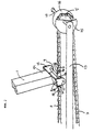
- a lower portion 24 of the driving member 1 has an attachment section 8, as best seen in Fig. 2.
- Fork members 11, 12 are attached to each end of the attachment section 8.
- the fork members are substantially parallel to one another and extend away from the ball bearing 2.
- a lateral rod member 9 extends between the fork members 11, 12 so that the rod member 9 is spaced apart from the attachment section 8.
- a bar segment 6 defines a central opening 26 that has the rod member 9 slidably inserted therein so that the bar segment 6 may slide sideways along and rotate about the rod member 9.
- the bar segment 6 has two opposite ends 28, 30 that are rotatably attached to end portions 32, 34, respectively, of an elongate chain 7.
- the frame 3 has a downwardly extending fork 14 that is rotatably attached to an inner end 36 of an elongate movable arm 13.
- the movable arm 13 may move relative to the fork 14 when the vehicle 50 is in use.
- An outer end 38 of the movable arm 13 is attached to a pin 10 that protrudes in a direction that is substantially perpendicular to the movable arm 13.
- a movable gear 5 is both shiftably and rotatably attached to the movable arm 13 and may slide sideways on the pin 10 and rotate about the pin 10, as desired.
- a pair of protective discs 15, 16 are attached to the movable gear 5 and disposed on each side of the movable gear 5 so that the protective discs may move with the movable gear 5 on the pin 10. The protective discs prevent the chain 7 from disengaging or jumping off the movable gear 5.
- the gear assembly 4 has a plurality of drive gears of different sizes and a shift mechanism so that the chain 7 can be moved from one drive gear to another drive gear to change the gear ratio of the gear assembly 4.
- the driving member 1 is not permitted to move sideways, only back and forth. Instead, the bar segment 6 and the movable gear 5 are moved sideways to follow the sideways movement of the chain 7.
- the gear assembly 4 has a first width and the attachment section 8 has a second width. The first; width is substantially similar to the second width.
Landscapes
- Engineering & Computer Science (AREA)
- Mechanical Engineering (AREA)
- Chemical & Material Sciences (AREA)
- Combustion & Propulsion (AREA)
- Transportation (AREA)
- Transmission Devices (AREA)
- Gears, Cams (AREA)
- Steering-Linkage Mechanisms And Four-Wheel Steering (AREA)
- Devices For Conveying Motion By Means Of Endless Flexible Members (AREA)
Abstract
Claims (17)
- Mécanisme d'entraínement pour un véhicule mû par la force des bras (50) comprenant un cadre (3), une chaíne (7) et une première roue (19), qui a un moyeu (17) fixé de façon tournante au cadre (3), le mécanisme d'entraínement comprenant un élément d'entraínement (1) et une attache de chaíne mobile (8) fixée à l'élément d'entraínement (1),
caractérisé en ce que :l'attache de chaíne (8) comporte des pattes formant fourchette mutuellement espacées (11, 12) et une tige (9) s'étendant entre celles-ci ; etle mécanisme d'entraínement comprend en outre :un bras mobile (13) dont une extrémité est fonctionnellement attachable à une jambe de fourche (14) qui est fixée au véhicule mû par la force des bras (50) ;un pignon mobile (5) en prise active avec l'autre extrémité du bras mobile (13) via un axe (10) ;un ensemble de pignons (4) en prise active avec la première roue (19) du véhicule (50) ;la chaíne (7) en prise active avec l'attache de chaíne mobile (8), le pignon mobile (5) et l'ensemble de pignons (4) ; etun disque de protection (15, 16) disposé de chaque côté du pignon mobile (5). - Mécanisme d'entraínement selon la revendication 1, dans lequel l'attache de chaíne mobile (8) comprend un segment de barre (6) qui est déplaçable latéralement sur la tige (9), et le pignon mobile (5) est déplaçable latéralement sur l'axe (10), de sorte que le segment de barre (6) et le pignon mobile (5) sont tous deux déplaçables sensiblement de la même distance lorsqu'on fait passer la chaíne (7) d'un premier pignon de l'ensemble de pignons (4) à un deuxième pignon de l'ensemble de pignons (4).
- Mécanisme d'entraínement selon la revendication 1, dans lequel l'ensemble de pignons (4) a une première largeur et les pattes de fourchette (11, 12) sont mutuellement espacées d'une première distance, la première largeur étant sensiblement la même que la première distance.
- Mécanisme d'entraínement selon la revendication 1, dans lequel le disque de protection (15, 16) comprend deux éléments de disque disposés de part et d'autre du pignon mobile (5), les éléments de disque étant fixés au pignon mobile (5) et montés de façon coulissante sur l'axe (10), de sorte que les éléments de disque peuvent suivre tout mouvement latéral et tout mouvement de rotation du pignon mobile (5).
- Mécanisme d'entraínement selon la revendication 3, dans lequel le segment de barre (6) comporte un premier trou, un deuxième trou et un troisième trou, la tige (9) étant insérée dans le deuxième trou et des parties d'extrémité de la chaíne (7) étant insérées dans les premier et troisième trous.
- Mécanisme d'entraínement selon la revendication 5, dans lequel les parties d'extrémité de la chaíne (7) sont attachées de façon tournante au segment de barre (6).
- Véhicule mû par la force des bras (50) comprenant un mécanisme d'entraínement selon la revendication 1, dans lequel l'élément d'entraínement (1) est attaché à un guidon (52) du véhicule mû par la force des bras (50).
- Véhicule mû par la force des bras (50) comprenant un mécanisme d'entraínement selon la revendication 7, dans lequel la chaíne (7) est déplaçable, par rapport au véhicule mû par la force des bras (50), de manière à faire tourner l'ensemble de pignons (4) lorsqu'on déplace l'élément d'entraínement (1) vers le pignon mobile (5).
- Véhicule mû par la force des bras (50) comprenant un mécanisme d'entraínement selon la revendication 1, dans lequel un guidon (52) du véhicule mû par la force des bras 50 est fonctionnellement attaché à l'élément d'entraínement (1) de sorte que, lorsqu'on déplace le guidon (52) en sens inverse des aiguilles d'une montre, l'élément d'entraínement (1) est déplacé en sens inverse des aiguilles d'une montre pour entraíner la chaíne (7).
- Mécanisme d'entraínement selon la revendication 1, dans lequel l'ensemble de pignons (4) a une première largeur et l'attache de chaíne (8) a une deuxième largeur, la première largeur étant sensiblement la même que la deuxième largeur.
- Véhicule mû par la force des bras (50) comprenant :caractérisé en ce que le véhicule entraíné par la force des bras (50) comprend en outre :un cadre (3);une fourche (14) fixée au cadre (3) ;une première roue (19) ayant un moyeu (17) qui est attaché de façon tournante à la fourche (14) ;un élément d'entraínement (1) attaché de façon pivotante au cadre (3), l'élément d'entraínement (1) étant déplaçable en mouvement alternatif pour entraíner le véhicule (50) vers l'avant ;une attache de chaíne mobile (8) fixée à l'élément d'entraínement (1),un bras mobile (13) dont une extrémité est fonctionnellement attachée à la fourche (14) ;un pignon mobile (5) en prise active avec le bras mobile (13);un ensemble de pignons (4) en prise active avec le moyeu (17) de la première roue (19) pour entraíner le véhicule mû par la force des bras (50) ; etune chaíne (7) en prise active avec l'attache de chaíne mobile (8), le pignon mobile (5) et l'ensemble de pignons (4).
- Véhicule mû par la force des bras (50) selon la revendication 11, dans lequel le cadre (3) a une deuxième roue (20) et un support horizontal (48) qui s'étend entre la première roue (10) et la deuxième roue (20).
- Véhicule mû par la force des bras (50) selon la revendication 11, dans lequel l'attache de chaíne mobile (8) est attachée à la chaíne (7) à un point qui est situé entre le pignon mobile (5) et l'ensemble de pignons (4).
- Véhicule mû par la force des bras (50) selon la revendication 11, dans lequel le bras mobile (13) est sensiblement perpendiculaire à la fourche (14) et s'étend vers l'extérieur et à l'opposé de l'ensemble de pignons (4).
- Véhicule mû par la force des bras (50) selon la revendication 1, dans lequel le bras mobile (13) et l'élément d'entraínement (1) sont sensiblement rectilignes.
- Véhicule mû par la force des bras (50) selon la revendication 1, dans lequel la première roue (19) possède une jante extérieure qui est située entre l'ensemble de pignons (4) et le pignon mobile (5).
- Véhicule mû par la force des bras (50) selon la revendication 11, dans lequel l'élément d'entraínement (1) est attaché à la chaíne (7) de sorte que la chaíne (7) entraíne la première roue (19) du véhicule (50) vers l'avant lorque l'élément d'entraínement (1) est déplacé vers le pignon mobile (5).
Applications Claiming Priority (3)
| Application Number | Priority Date | Filing Date | Title |
|---|---|---|---|
| SE9501633A SE507485C2 (sv) | 1995-05-03 | 1995-05-03 | Drivanordning för ett armdrivet fordon |
| SE9501633 | 1995-05-03 | ||
| PCT/SE1996/000590 WO1996034791A1 (fr) | 1995-05-03 | 1996-05-03 | Dispositif d'entrainement |
Publications (2)
| Publication Number | Publication Date |
|---|---|
| EP0824444A1 EP0824444A1 (fr) | 1998-02-25 |
| EP0824444B1 true EP0824444B1 (fr) | 2001-11-28 |
Family
ID=20398174
Family Applications (1)
| Application Number | Title | Priority Date | Filing Date |
|---|---|---|---|
| EP96913767A Expired - Lifetime EP0824444B1 (fr) | 1995-05-03 | 1996-05-03 | Dispositif d'entrainement |
Country Status (6)
| Country | Link |
|---|---|
| US (1) | US5997020A (fr) |
| EP (1) | EP0824444B1 (fr) |
| AU (1) | AU5661896A (fr) |
| DE (1) | DE69617416T2 (fr) |
| SE (1) | SE507485C2 (fr) |
| WO (1) | WO1996034791A1 (fr) |
Families Citing this family (7)
| Publication number | Priority date | Publication date | Assignee | Title |
|---|---|---|---|---|
| AU2003264423A1 (en) * | 2002-09-18 | 2004-04-08 | France Bed Co., Ltd. | Manual bicycle |
| RU2258626C1 (ru) * | 2004-11-02 | 2005-08-20 | Иосселиани Дмитрий Александрович | Велосипед с передним ручным приводом |
| RU2258628C1 (ru) * | 2004-12-09 | 2005-08-20 | Иосселиани Дмитрий Александрович | Велосипед с передним рычажным приводом и раздельными гибкими передачами |
| DE102008057400B3 (de) | 2008-11-14 | 2010-06-24 | Löhr, Valentin | Roller mit Handhebelantrieb |
| US8388004B2 (en) * | 2010-05-12 | 2013-03-05 | Edward Walter | Personal transportation device |
| CA2899856A1 (fr) | 2013-01-30 | 2014-08-07 | Paul Sprague | Systeme de propulsion pour vehicules a propulsion humaine |
| CN108999945A (zh) * | 2017-11-01 | 2018-12-14 | 郭俱全 | 一种摇杆驱动式车轮动力机构 |
Family Cites Families (8)
| Publication number | Priority date | Publication date | Assignee | Title |
|---|---|---|---|---|
| US2732221A (en) * | 1956-01-24 | Hand propelled vehicle | ||
| FR930112A (fr) * | 1946-07-02 | 1948-01-16 | Système de propulsion pour cycles et véhicules similaires | |
| FR1138622A (fr) * | 1954-12-20 | 1957-06-17 | Perfectionnements apportés aux dispositifs de propulsion pour bicyclettes et analogues | |
| US4189166A (en) * | 1977-12-29 | 1980-02-19 | Ben Lindsey | Self-propelled vehicle |
| US4548420A (en) * | 1983-12-05 | 1985-10-22 | Patroni Jr Anthony F | Reciprocating and oscillating drive mechanism |
| DE4000514A1 (de) * | 1990-01-10 | 1991-08-22 | Thomas Siebker | Aerodynamisches fahrrad mit geradlinigem antrieb ueber fuehrungsschiene |
| IT1251219B (it) * | 1991-11-06 | 1995-05-04 | Francesco Bono | "meccanismo per rendere motrice la ruota anteriore folle di biciclettein genere". |
| US5833256A (en) * | 1995-11-20 | 1998-11-10 | Gilmore; Roger C. | User powered vehicle and propulsion mechanism |
-
1995
- 1995-05-03 SE SE9501633A patent/SE507485C2/sv not_active IP Right Cessation
-
1996
- 1996-05-03 AU AU56618/96A patent/AU5661896A/en not_active Abandoned
- 1996-05-03 DE DE69617416T patent/DE69617416T2/de not_active Expired - Fee Related
- 1996-05-03 EP EP96913767A patent/EP0824444B1/fr not_active Expired - Lifetime
- 1996-05-03 WO PCT/SE1996/000590 patent/WO1996034791A1/fr not_active Ceased
-
1997
- 1997-10-27 US US08/958,624 patent/US5997020A/en not_active Expired - Fee Related
Also Published As
| Publication number | Publication date |
|---|---|
| AU5661896A (en) | 1996-11-21 |
| DE69617416D1 (de) | 2002-01-10 |
| SE9501633D0 (sv) | 1995-05-03 |
| EP0824444A1 (fr) | 1998-02-25 |
| DE69617416T2 (de) | 2002-05-29 |
| US5997020A (en) | 1999-12-07 |
| SE9501633L (sv) | 1996-11-04 |
| SE507485C2 (sv) | 1998-06-15 |
| WO1996034791A1 (fr) | 1996-11-07 |
Similar Documents
| Publication | Publication Date | Title |
|---|---|---|
| US7111860B1 (en) | Treadle scooter | |
| US4639007A (en) | Exercise vehicle | |
| US5876052A (en) | Health exercise equipment propelled by simulated rowing motion | |
| US7044488B1 (en) | Scooter assembly | |
| US5332244A (en) | Bicycle with selectably engageable single or dual wheel drive | |
| EP0824444B1 (fr) | Dispositif d'entrainement | |
| US6585277B1 (en) | Hand powered cart | |
| US5038881A (en) | Reverse-shift mechanism for snowmobiles | |
| US4641847A (en) | Single lever control wheel chair | |
| US4911457A (en) | Scooter | |
| EP1764281A2 (fr) | Châssis d'une poussette avec un mécanisme pour changer la direction du siège | |
| US4667975A (en) | Hand-powered toy vehicle | |
| US2725945A (en) | Selective brake control mechanism for tractor steering | |
| US4624321A (en) | Lawn edger wheel mechanism | |
| JPH08337131A (ja) | 不整地走行車のチェンジ装置 | |
| JPH01156160A (ja) | 車輌のブレーキ操作装置 | |
| JPH046393Y2 (fr) | ||
| EP1372564B1 (fr) | Mecanisme d'entrainement manuel pour vehicule a trois ou plus de trois roues | |
| JPS6328013Y2 (fr) | ||
| JP3072470B2 (ja) | 車椅子 | |
| CN212047729U (zh) | 自力式儿滑车 | |
| EP0835795A2 (fr) | Poussette pour enfant avec frein de stationnement | |
| JPH063699Y2 (ja) | 移動農機の後進耕耘牽制装置 | |
| KR200420087Y1 (ko) | 포크형 전륜조향장치를 구비한 자전거 | |
| JPH0740412Y2 (ja) | 自走台車の走行安全装置 |
Legal Events
| Date | Code | Title | Description |
|---|---|---|---|
| PUAI | Public reference made under article 153(3) epc to a published international application that has entered the european phase |
Free format text: ORIGINAL CODE: 0009012 |
|
| 17P | Request for examination filed |
Effective date: 19971112 |
|
| AK | Designated contracting states |
Kind code of ref document: A1 Designated state(s): DE FR GB IT |
|
| 17Q | First examination report despatched |
Effective date: 19990730 |
|
| GRAG | Despatch of communication of intention to grant |
Free format text: ORIGINAL CODE: EPIDOS AGRA |
|
| GRAG | Despatch of communication of intention to grant |
Free format text: ORIGINAL CODE: EPIDOS AGRA |
|
| GRAH | Despatch of communication of intention to grant a patent |
Free format text: ORIGINAL CODE: EPIDOS IGRA |
|
| GRAH | Despatch of communication of intention to grant a patent |
Free format text: ORIGINAL CODE: EPIDOS IGRA |
|
| GRAA | (expected) grant |
Free format text: ORIGINAL CODE: 0009210 |
|
| AK | Designated contracting states |
Kind code of ref document: B1 Designated state(s): DE FR GB IT |
|
| REG | Reference to a national code |
Ref country code: GB Ref legal event code: IF02 |
|
| REF | Corresponds to: |
Ref document number: 69617416 Country of ref document: DE Date of ref document: 20020110 |
|
| ET | Fr: translation filed | ||
| PLBE | No opposition filed within time limit |
Free format text: ORIGINAL CODE: 0009261 |
|
| STAA | Information on the status of an ep patent application or granted ep patent |
Free format text: STATUS: NO OPPOSITION FILED WITHIN TIME LIMIT |
|
| 26N | No opposition filed | ||
| PGFP | Annual fee paid to national office [announced via postgrant information from national office to epo] |
Ref country code: IT Payment date: 20060531 Year of fee payment: 11 |
|
| PGFP | Annual fee paid to national office [announced via postgrant information from national office to epo] |
Ref country code: DE Payment date: 20070522 Year of fee payment: 12 |
|
| PGFP | Annual fee paid to national office [announced via postgrant information from national office to epo] |
Ref country code: GB Payment date: 20080522 Year of fee payment: 13 |
|
| PG25 | Lapsed in a contracting state [announced via postgrant information from national office to epo] |
Ref country code: DE Free format text: LAPSE BECAUSE OF NON-PAYMENT OF DUE FEES Effective date: 20081202 |
|
| PG25 | Lapsed in a contracting state [announced via postgrant information from national office to epo] |
Ref country code: IT Free format text: LAPSE BECAUSE OF NON-PAYMENT OF DUE FEES Effective date: 20070503 |
|
| GBPC | Gb: european patent ceased through non-payment of renewal fee |
Effective date: 20090503 |
|
| REG | Reference to a national code |
Ref country code: FR Ref legal event code: ST Effective date: 20100129 |
|
| PG25 | Lapsed in a contracting state [announced via postgrant information from national office to epo] |
Ref country code: FR Free format text: LAPSE BECAUSE OF NON-PAYMENT OF DUE FEES Effective date: 20090602 |
|
| PGFP | Annual fee paid to national office [announced via postgrant information from national office to epo] |
Ref country code: FR Payment date: 20080425 Year of fee payment: 13 |
|
| PG25 | Lapsed in a contracting state [announced via postgrant information from national office to epo] |
Ref country code: GB Free format text: LAPSE BECAUSE OF NON-PAYMENT OF DUE FEES Effective date: 20090503 |