EP0824785B1 - Sekundär-überwachungsradar - Google Patents
Sekundär-überwachungsradar Download PDFInfo
- Publication number
- EP0824785B1 EP0824785B1 EP96913628A EP96913628A EP0824785B1 EP 0824785 B1 EP0824785 B1 EP 0824785B1 EP 96913628 A EP96913628 A EP 96913628A EP 96913628 A EP96913628 A EP 96913628A EP 0824785 B1 EP0824785 B1 EP 0824785B1
- Authority
- EP
- European Patent Office
- Prior art keywords
- power
- signals
- secondary surveillance
- surveillance radar
- phase
- Prior art date
- Legal status (The legal status is an assumption and is not a legal conclusion. Google has not performed a legal analysis and makes no representation as to the accuracy of the status listed.)
- Expired - Lifetime
Links
- 238000012544 monitoring process Methods 0.000 claims description 11
- 238000000034 method Methods 0.000 claims description 9
- 230000001419 dependent effect Effects 0.000 claims description 4
- 230000010363 phase shift Effects 0.000 abstract description 6
- 241000347389 Serranus cabrilla Species 0.000 abstract 1
- 230000003321 amplification Effects 0.000 abstract 1
- 238000003199 nucleic acid amplification method Methods 0.000 abstract 1
- 239000013598 vector Substances 0.000 description 7
- 230000005540 biological transmission Effects 0.000 description 6
- 238000010586 diagram Methods 0.000 description 2
- 238000012545 processing Methods 0.000 description 2
- RZVHIXYEVGDQDX-UHFFFAOYSA-N 9,10-anthraquinone Chemical compound C1=CC=C2C(=O)C3=CC=CC=C3C(=O)C2=C1 RZVHIXYEVGDQDX-UHFFFAOYSA-N 0.000 description 1
- 238000004891 communication Methods 0.000 description 1
- 239000000446 fuel Substances 0.000 description 1
- 230000005855 radiation Effects 0.000 description 1
- 238000012552 review Methods 0.000 description 1
- 239000007787 solid Substances 0.000 description 1
- 230000003068 static effect Effects 0.000 description 1
Images
Classifications
-
- H—ELECTRICITY
- H03—ELECTRONIC CIRCUITRY
- H03G—CONTROL OF AMPLIFICATION
- H03G3/00—Gain control in amplifiers or frequency changers
- H03G3/20—Automatic control
- H03G3/30—Automatic control in amplifiers having semiconductor devices
- H03G3/3036—Automatic control in amplifiers having semiconductor devices in high-frequency amplifiers or in frequency-changers
-
- G—PHYSICS
- G01—MEASURING; TESTING
- G01S—RADIO DIRECTION-FINDING; RADIO NAVIGATION; DETERMINING DISTANCE OR VELOCITY BY USE OF RADIO WAVES; LOCATING OR PRESENCE-DETECTING BY USE OF THE REFLECTION OR RERADIATION OF RADIO WAVES; ANALOGOUS ARRANGEMENTS USING OTHER WAVES
- G01S13/00—Systems using the reflection or reradiation of radio waves, e.g. radar systems; Analogous systems using reflection or reradiation of waves whose nature or wavelength is irrelevant or unspecified
- G01S13/74—Systems using reradiation of radio waves, e.g. secondary radar systems; Analogous systems
- G01S13/76—Systems using reradiation of radio waves, e.g. secondary radar systems; Analogous systems wherein pulse-type signals are transmitted
- G01S13/78—Systems using reradiation of radio waves, e.g. secondary radar systems; Analogous systems wherein pulse-type signals are transmitted discriminating between different kinds of targets, e.g. IFF-radar, i.e. identification of friend or foe
- G01S13/781—Secondary Surveillance Radar [SSR] in general
Definitions
- This invention relates to a secondary surveillance radar and has particular but not exclusive application to a Mode-S radar for determining the position and identity of aircraft.
- a primary radar system radar signals transmitted from an antenna are reflected by remote targets such as aircraft to produce returns.
- a receiver connected to the antenna processes the returns to determine the range and azimuth of the target.
- the identity of targets such as aircraft is determined by the use of transponders on each aircraft, which are interrogated by the transmitted radar signals.
- SSR secondary surveillance radar
- a ground radar station, termed the interrogator transmits an interrogation signal at a radio frequency of 1030 MHz, which interrogates transponders that transmit a reply to the interrogator at a radio frequency of 1090 MHz.
- the interrogator transmits r.f. energy by means of an antenna with a rotating directive pattern, which is usually constituted by a mechanical rotating antenna, but which may comprise a stationary, electronically steered phased array antenna, which has broad elevation and narrow azimuth.
- a rotating directive pattern which is usually constituted by a mechanical rotating antenna, but which may comprise a stationary, electronically steered phased array antenna, which has broad elevation and narrow azimuth.
- Mode-S SSR includes two main features.
- the first feature allows each aircraft transponder to be given a 25 bit address which is unique world-wide. Interrogation can therefore be directed at a specific aircraft and hence be selective, and the aircraft reply also contains its unique address.
- the feature allows enhanced signal processing of the reply signal by the interrogator.
- the second feature allows the automatic transmission of both ground to air and air to ground, of a large quantity of data usually communicated between Air Traffic Control and the pilot of the aircraft by VHF voice communication.
- the automatic transmission between the ground and the aircraft in a Mode-S SSR may include transmission from the ground of flight control information and local weather conditions, and transmission from the air of data concerning fuel reserves, engine performance and weather.
- the interrogator for an SSR should have the capability for its transmitted power to be varied during the rotation cycle of the antenna directive pattern.
- the range of interrogation is a function of the power of the transmitted radar signals and so by varying the power, the system can be selective in terms of range.
- the power variation required is typically over a range of 12dB down from the maximum transmitted power in increments of 2dB.
- the setting accuracy at each power level is typically ⁇ 1dB and the time to switch between any power level is typically in the range 10 to 50 microseconds.
- a secondary surveillance radar including: transmitter means for transmitting radar signals for interrogating transponders on remote targets; receiver means for receiving returns from the interrogated transponders on the targets; and a controllable power source for producing r.f. signals for the transmitter means, comprising means for producing first and second r.f. signals having a predetermined phase relationship; phase setting means for setting the phase relationship between the first and second signals selectively; first and second power amplifier means for amplifying the first and second signals respectively; and power combining means for combining the first and second signals amplified by the power amplifier means whereby to provide an amplified r.f. output signal of a power dependent upon the phase relationship set by the phase setting means.
- the transmitted power can be controlled sufficiently rapidly to meet the aforementioned requirements for a Mode-S SSR.
- the invention also extends to a method of operating a secondary surveillance radar including: transmitting radar signals so as to interrogate transponders on remote targets; receiving returns from the interrogated transponders on the targets; and controlling the power of the signals produced by the transmitter means, comprising producing first and second r.f. signals; selectively setting the phase relationship between the first and second signals, amplifying the first and second signals respectively; combining the first and second signals amplified by the power amplifier means whereby to provide an amplified r.f. output signal of a power dependent upon the set phase relationship; and feeding the output signal to the transmitting means.
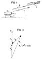
- a ground based Mode-S SSR interrogator 1 is provided with a rotary antenna 2 which transmits radar signals 3 for interrogating transponders on aircraft such as aircraft 4.
- the antenna 2 is also used to receive returns 5 from the interrogated transponders, which are passed to a receiver in the interrogator 1.
- the interrogator is typically connected by a land line to a control station (not shown).
- the antenna 2 has a directive pattern that rotates, and in the embodiment shown in Figure 1, the antenna is a mechanical rotary array.
- the static array which is electronically steerable could also be used.
- the system shown in Figure 1 uses a monopulse transmission technique. Two beams are used comprising a main beam which produces what is generally known as a sum pattern, together with a further beam which produces what is known as the difference pattern.
- the sum pattern comprises a main lobe arranged on the boresight of the antenna whereas the difference pattern comprises side lobes disposed symmetrically on opposite sides of the boresight, which exhibits 180 degrees phase reversal at its null.
- the pattern allows an accurate estimation of the off-boresight azimuth of the transponder on the aircraft to be made by comparing the amplitudes and phases of signals obtained from the two patterns.
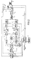
- circuits are shown for providing r.f. power to the antenna for the sum antenna beam. It will be appreciated that a corresponding circuit for an omnidirectional antenna beam will also be provided as in a conventional SSR, but it is not shown fully in Figure 2 for purposes of clarity.
- the controllable power source includes a r.f. source and modulator circuit 6 which generates a continuous wave interrogation signal at a radio frequency of 1030 MHz, which is pulse modulated under the control of a monitoring and control module 7.
- the pulse modulation encodes the interrogation signal with data to be transmitted to the aircraft 4 in accordance with the Mode-S SSR protocol.
- the pulse modulated output is provided on line 8 to a main driver amplifier circuit 9 shown within dotted outline.
- the main driver amplifier 9 controls the power fed to the main beam.
- the modulator also provides on line 10 an output, which is modulated with a different data stream, for use in providing the omnidirectional pattern and the power is controlled by another drive amplifier, similar to amplifier 9 (not shown). Since the circuits for the omnidirectional pattern are similar to those for the main beam pattern they will not be described further.
- the main drive amplifier 9 includes a power splitter 11, which has an input 12 to receive signals from line 8, and first and second outputs 13, 14 that provide signals of equal amplitude and phase V a and V b on first and second channels a , b.
- the signals V a and V b are fed through respective pre-amplifiers 15, 16 and drive amplifiers 17, 18 and then through isolators 19, 20 to respective first and second main power amplifiers 21, 22.
- the outputs of the first and second main power amplifiers 21, 22 are fed to a power combiner 23, the output of which is fed through a bandpass filter 24 and a circulator 25 to a port 26 for the main antenna beam.
- the pulse modulated signals on line 8 are amplified in the respective channels a, b, initially by amplifiers 15 and 17, and 16 and 18, and then by means of power amplifiers 21 and 22, the resulting amplifier signals being combined in power combiner 23 and fed to port 26 to act as interrogation signals for the aircraft transponders. Returns from the transponders are received from the antenna and fed to port 26.
- the circulator 25 directs the returns on line 27 to a receiver circuit 28 which demodulates the returns using a local oscillator (not shown) which is locked in frequency to the r.f. source 6 over line 29. Also, the receiver 28 receives corresponding antenna returns from the difference pattern on line 30 and the omnidirectional pattern on line 40, and the signals are processed in a manner known per se in order to obtain aircraft identification and other operating data transmitted from the aircraft transponder. Also, the aircraft range and azimuth are computed in a manner known per se depending on the time delay between an initial transmitted interrogation pulse and the corresponding return received from the transponder, together with data concerning the angle of rotation of the antenna directive patterns. Such signal processing is known per se and will not be described further herein.
- the resulting data from the receiver 28 is fed (by means not shown) into radar control computers 31 which enable the aircraft to be tracked. Also, the computers determine the data that is transmitted to the aircraft by controlling the pulse modulation of source 6 through the control and monitoring circuit 7.
- the amplifiers shown in Figure 2 typically provide a maximum peak pulse power at port 26 of 1950 watts, corresponding to 62.9dBm.
- the Mode-S SSR specification requires that the power at port 26 to be reduced from maximum, in 2dB steps down to the value of 12dB below maximum i.e. down to 50.9dBm.
- phase shifter 32 which varies the phase of signal V b relative to the phase of signal V a . This is shown schematically in Figure 3.
- phase vectors V a and V b are in phase, i.e. no phase shift is produced by the phase shifter 32, the phase vectors are aligned as shown in dotted outline so that the resulting phase vector produced by the combination of the signals in power combiner 23, is 2V. Conversely, when the phase vectors are in antiphase, the resultant power drops to zero.
- the amplitude of the resultant combination V R produced by the power combiner 23 can be varied between zero and 2V.
- the phase angle ⁇ produced by the phase shifter 32 is set by control circuit 33 under the control of the radar computers 31 through monitoring and control circuit 7.
- the radar computers 31 can set the desired range of operation of the radar by controlling the output power produced at port 26, by altering the phase shift produced by phase shifter 32.
- the phase shift can be performed rapidly, in a range of 10 to 50 microseconds, to an accuracy of ⁇ 1dB in incremental steps of 2dB, so as to allow the range to be selected during rotation of the antenna directive pattern.
- the phase shifter 32 may in practice comprise a model QQ-1668 manufactured by KDI/Triangle Electronics Inc., East Hanover, New Jersey 07936, USA.
- circuits are provided to monitor and control the power level dynamically to a particular set value.
- a power monitor 34 is connected to the port 26, which provides signals indicative of the dynamic output power on lines 35 to the monitoring and control circuit 7.
- the signals are compared with reference values indicative of the required output power level determined by the radar computers 31.
- the signal indicative of the difference between the actual monitored power level and the required value is fed to control circuit 33 in order to produce a small adjustment of the phase shift produced by phase shifter 32 in order to return the output power level to the required value.
- the required value of the output power will vary dynamically during rotation of the antenna directive pattern, under the control of the radar computers 31, and the described feedback loop causes the output power to be maintained at the required value.
- Additional control loops are provided in order to monitor the signals V a and V b during operation.
- power monitors 36, 37 and 38 are coupled respectively to the input 12 of the power splitter 11, and the outputs of driver amplifiers 17, 18.
- the monitors 36, 37, 38 provide respective inputs to the control circuit 33 so that the phase shifter 32 can be operated to compensate for operational variations in the amplitude and/or phase of the respective monitored signals.
- the operational temperature of the drive circuit 9 is monitored by a temperature monitor circuit 39 and the gain of the amplifiers 17, 18 is controlled to compensate for gain variations that otherwise might be caused by changes in temperature.
- the transmitted power at port 26 can be varied dynamically as the antenna directive pattern is rotated, so as to allow dynamic range selection.
- the invention has been described by way of example with reference to a Mode-S SSR, it will be appreciated that the invention can be used in other secondary surveillance radars where rapid and accurate power control is required for other operational rasons e.g. to reduce transmitted power over specified azimuth sectors in which radiation at full power would interfere with other radars or electronic equipment.
Landscapes
- Engineering & Computer Science (AREA)
- Radar, Positioning & Navigation (AREA)
- Remote Sensing (AREA)
- Computer Networks & Wireless Communication (AREA)
- Physics & Mathematics (AREA)
- General Physics & Mathematics (AREA)
- Radar Systems Or Details Thereof (AREA)
- Burglar Alarm Systems (AREA)
- Variable-Direction Aerials And Aerial Arrays (AREA)
- Amplifiers (AREA)
Claims (22)
- Sekundär-Überwachungsradar, der folgendes einschließt:ein Sendermittel (2, 3) zum Senden von Radarsignalen zum Abfragen von Transpondern auf entfernten Zielen;ein Empfängermittel (2,5) zum Empfangen von Rückgaben von den abgefragten Transpondern auf den Zielen; undeine regelbare Leistungsquelle (9, 21, 22, 23) zum Herstellen von HF-Signalen für das Sendermittel, die ein Mittel (11) umfasst, um erste und zweite HF-Signale mit einem vorbestimmten Phasenverhältnis herzustellen; ein Phaseneinstellungsmittel (32, 33) zum Einstellen des Phasenverhältnisses wahlweise zwischen den ersten und zweiten Signalen; erste und zweite Leistungsverstärkermittel (21, 22) zum Verstärken jeweils der ersten und zweiten Signale; und Leistungskombinierungsmittel (23) zum Kombinieren der ersten und zweiten von dem Verstärkermittel verstärkten Signale, um dabei ein verstärktes HF-Ausgabesignal einer Leistung zu liefern, die von dem Phasenverhältnis abhängt, das von dem Phaseneinstellungsmittel eingestellt ist.
- Sekundär-Überwachungsradar nach Anspruch 1, worin die regelbare Leistungsquelle erste und zweite Kanäle für die ersten und zweiten Signale einschließt, ein Mittel, das eine HF-Quelle liefert, und ein Mittel zum Liefern der ersten und zweiten Signale von der HF-Quelle in jeweils erste und zweite Kanäle.
- Sekundär-Überwachungsradar nach Anspruch 2, worin die HF-Quelle einen HF-Oszillator umfasst, und ein Leistungsaufspaltungsmittel mit einer an den Oszillator gekuppelte Eingabe und jeweils an den Kanälen angeschlossenen ersten und zweiten Ausgaben einschließt.
- Sekundär-Überwachungsradar nach Anspruch 2 oder 3, der erste und zweite Antriebsverstärker jeweils in den ersten und zweiten Kanälen umfasst.
- Sekundär-Überwachungsradar nach Anspruch 4, der ein Temperaturüberwachungsmittel umfasst, und ein Mittel zum Regeln der Gewinne der Antriebsverstärker als Funktion der überwachten Temperatur.
- Sekundär-Überwachungsradar nach Anspruch 4 oder 5 der erste und zweite Vorverstärker für die Antriebsverstärker in jeweils den ersten und zweiten Kanälen einschließt.
- Sekundär-Überwachungsradar nach einem der Ansprüche 2 bis 6, worin das Phaseneinstellungsmittel einen Phasenschieber in einem der Kanäle umfasst.
- Sekundär-Überwachungsradar nach einem der Ansprüche 2 bis 7, der ein Leistungsüberwachungsmittel zum Überwachen der Leistungspegel in jeweils den ersten und zweiten Kanälen einschließt, und ein Antriebsregelmittel zum Regeln des von dem Phaseneinstellungsmittel eingestellten Phasenverhältnisses in Abhängigkeit von den überwachten Leistungspegeln.
- Sekundär-Überwachungsradar nach einem der Ansprüche 2 bis 8, das ein Mittel zum Überwachen der Eingabeleistung des von der HF-Quelle zu dem Spaltungsmittel gebrachten HF-Signals einschließt, und ein Antriebsregelmittel zum Regeln des von dem Phaseneinstellungsmittels eingestellten Phasenverhältnisses in Abhängigkeit von der überwachten Eingabeleistung.
- Sekundär-Überwachungsradar nach einem vorhergehenden Anspruch, das ein Leistungsüberwachungsmittel zum Überwachen der Leistung des verstärkten HF-Ausgabesignals von dem Leistungskombinierungsmittel einschließt, und ein Regelmittel zum Regeln des von dem Phaseneinstellungsmittel eingestellten Phasenverhältnisses in Abhängigkeit von der überwachten Leistung des Ausgabesignals.
- Sekundär-Überwachungsradar nach einem vorhergehenden Anspruch, der ein Modulatormittel zum Modulieren der regelbaren Leistungsquelle einschließt.
- Sekundär-Überwachungsradar nach Anspruch 11, worin das Modulatormittel die HF-Signale für das Sendermittel Daten impulsmoduliert, die zu den Zielen gesendet werden sollen.
- Sekundär-Überwachungsradar nach einem vorhergehenden Anspruch, worin das Empfängermittel operativ ist, um Rückgaben von den abgefragten Transpondern zu demodulieren. um Daten davon abzuleiten.
- Sekundär-Überwachungsradar nach einem vorhergehenden Anspruch, worin das Sendermittel eine Antenne mit einem sich drehenden Richtmuster einschließt.
- Sekundär-Überwachungsradar nach einem vorhergehenden Anspruch, worin das Sendermittel und das Empfängermittel eine gemeinsame Antenne benutzen.
- Sekundär-Überwachungsradar nach einem vorhergehenden Anspruch, das Bereichsauswahlmittel zum Regeln des Phaseneinstellungsmittels einschließt, um die Ausgabeleistung des Sendermittels zu regeln.
- Modul-S SSR nach einem vorhergehenden Anspruch.
- Verfahren zum Betreiben eines Sekundär-Überwachungsradars, das folgendes einschließt:Senden von Radarsignalen (2, 3), um Transponder auf entfernten Zielen abzufragen; Empfangen von Rückgaben (2, 5) von den abgefragten Transpondern auf den Zielen; und Regeln (9) der Leistung der von dem Sendermittel hergestellten Signalen, das Herstellen von ersten und zweiten HF-Signalen (11) umfasst, wahlweises Einstellen des Phasenverhältnisses zwischen den ersten und zweiten Signalen (32), Verstärken jeweils der ersten und zweiten Signale (21, 22); Kombinieren (23) der von dem Leistungsverstärkermittel verstärkten ersten und zweiten Signale, um dadurch ein verstärktes HF-Ausgabesignal einer von dem eingestellten Phasenverhältnis abhängigen Leistung zu liefern; und Zubringen (24, 26) des Ausgabesignals zu dem Sendemittel.
- Verfahren nach Anspruch 18. das Überwachen der Ausgabeleistung für die gesendeten Radarsignale und Konstanthalten der Leistung davon für eine gegebene Dauer durch Regeln des Phasenverhältnisses einschließt.
- Verfahren nach Anspruch 18 oder 19, das Modulieren der gesendeten Radarsignale mit Daten einschließt, die von dem Ziel empfangen werden sollen.
- Verfahren nach Anspruch 18, 19 oder 20, das Entschlüsseln von Daten einschließt, die von dem Ziel gesendet werden.
- Verfahren zum Betreiben eines Modul-S SSRs nach einem der Ansprüche 18 bis 21.
Priority Applications (2)
| Application Number | Priority Date | Filing Date | Title |
|---|---|---|---|
| EP96913628A EP0824785B1 (de) | 1995-05-11 | 1996-05-03 | Sekundär-überwachungsradar |
| GR990402830T GR3031735T3 (en) | 1995-05-11 | 1999-11-03 | Secondary surveillance radar |
Applications Claiming Priority (4)
| Application Number | Priority Date | Filing Date | Title |
|---|---|---|---|
| EP95303181 | 1995-05-11 | ||
| EP95303181 | 1995-05-11 | ||
| EP96913628A EP0824785B1 (de) | 1995-05-11 | 1996-05-03 | Sekundär-überwachungsradar |
| PCT/GB1996/001100 WO1996036110A1 (en) | 1995-05-11 | 1996-05-03 | Secondary surveillance radar |
Publications (2)
| Publication Number | Publication Date |
|---|---|
| EP0824785A1 EP0824785A1 (de) | 1998-02-25 |
| EP0824785B1 true EP0824785B1 (de) | 1999-08-04 |
Family
ID=8221192
Family Applications (1)
| Application Number | Title | Priority Date | Filing Date |
|---|---|---|---|
| EP96913628A Expired - Lifetime EP0824785B1 (de) | 1995-05-11 | 1996-05-03 | Sekundär-überwachungsradar |
Country Status (10)
| Country | Link |
|---|---|
| US (1) | US5920277A (de) |
| EP (1) | EP0824785B1 (de) |
| CN (1) | CN1104088C (de) |
| AT (1) | ATE183035T1 (de) |
| AU (1) | AU5655096A (de) |
| DE (1) | DE69603596T2 (de) |
| ES (1) | ES2137691T3 (de) |
| GR (1) | GR3031735T3 (de) |
| RU (1) | RU2146379C1 (de) |
| WO (1) | WO1996036110A1 (de) |
Families Citing this family (24)
| Publication number | Priority date | Publication date | Assignee | Title |
|---|---|---|---|---|
| US7570214B2 (en) | 1999-03-05 | 2009-08-04 | Era Systems, Inc. | Method and apparatus for ADS-B validation, active and passive multilateration, and elliptical surviellance |
| US7777675B2 (en) | 1999-03-05 | 2010-08-17 | Era Systems Corporation | Deployable passive broadband aircraft tracking |
| US7667647B2 (en) | 1999-03-05 | 2010-02-23 | Era Systems Corporation | Extension of aircraft tracking and positive identification from movement areas into non-movement areas |
| US7612716B2 (en) | 1999-03-05 | 2009-11-03 | Era Systems Corporation | Correlation of flight track data with other data sources |
| US8446321B2 (en) | 1999-03-05 | 2013-05-21 | Omnipol A.S. | Deployable intelligence and tracking system for homeland security and search and rescue |
| US7889133B2 (en) | 1999-03-05 | 2011-02-15 | Itt Manufacturing Enterprises, Inc. | Multilateration enhancements for noise and operations management |
| US8203486B1 (en) | 1999-03-05 | 2012-06-19 | Omnipol A.S. | Transmitter independent techniques to extend the performance of passive coherent location |
| US7739167B2 (en) | 1999-03-05 | 2010-06-15 | Era Systems Corporation | Automated management of airport revenues |
| US7782256B2 (en) | 1999-03-05 | 2010-08-24 | Era Systems Corporation | Enhanced passive coherent location techniques to track and identify UAVs, UCAVs, MAVs, and other objects |
| US7908077B2 (en) | 2003-06-10 | 2011-03-15 | Itt Manufacturing Enterprises, Inc. | Land use compatibility planning software |
| AU6901700A (en) * | 1999-09-10 | 2001-04-10 | Preco, Inc. | System and method for short range radar |
| US6608601B1 (en) * | 1999-12-21 | 2003-08-19 | Lockheed Martin Corporation | Integrated antenna radar system for mobile and transportable air defense |
| FR2812949B1 (fr) * | 2000-08-11 | 2003-04-25 | Thomson Csf | Procede et dispositif de codage/decodage de la repartition de puissance sur les sorties d'un systeme |
| US6617997B2 (en) * | 2002-01-03 | 2003-09-09 | Aviation Communication & Surveillance Systems, Llc | Method of determining radio frequency link reliability in an aircraft tracking system |
| US6809679B2 (en) * | 2002-09-05 | 2004-10-26 | Massachusetts Institute Of Technology | Surveillance system and method for aircraft approach and landing |
| GB2412027B (en) * | 2004-03-08 | 2007-04-11 | Raytheon Systems Ltd | Secondary radar message decoding |
| WO2008051292A2 (en) * | 2006-04-10 | 2008-05-02 | Aviation Communication & Surveillance Systems Llc | Systems and methods of providing whisper shout surveillance with a tcas |
| US7965227B2 (en) | 2006-05-08 | 2011-06-21 | Era Systems, Inc. | Aircraft tracking using low cost tagging as a discriminator |
| RU2321021C1 (ru) * | 2006-10-11 | 2008-03-27 | Войсковая часть 45807 | Радиолокационный ответчик |
| CN101750605B (zh) * | 2009-12-22 | 2012-07-04 | 宁波成电泰克电子信息技术发展有限公司 | 一种基于航管二次雷达测试系统的抗干扰处理方法 |
| CN102736068B (zh) * | 2012-06-19 | 2014-07-02 | 零八一电子集团有限公司 | 自适应识别多站异步信号干扰的跟踪处理方法 |
| RU2543514C2 (ru) * | 2013-07-15 | 2015-03-10 | Российская Федерация, от имени которой выступает Министерство обороны Российской Федерации | Способ формирования сигналов и передачи информации в ответном канале системы радиолокационного опознавания |
| RU2606386C2 (ru) * | 2013-08-15 | 2017-01-10 | Открытое акционерное общество "Азимут" | Моноимпульсная вторичная радиолокационная система с режимом S |
| WO2026003779A1 (en) * | 2024-06-27 | 2026-01-02 | Leonardo S.P.A. | Interrogator device for a radar system, having improved performance |
Family Cites Families (9)
| Publication number | Priority date | Publication date | Assignee | Title |
|---|---|---|---|---|
| GB2050744B (en) * | 1979-06-05 | 1983-04-20 | Marconi Co Ltd | Secondary surveillance radar |
| JPS61100029A (ja) * | 1984-10-22 | 1986-05-19 | Toshiba Corp | 送信装置 |
| RU2029971C1 (ru) * | 1989-01-31 | 1995-02-27 | Артемов Владимир Тарасович | Способ радиолокационного запроса - ответа и запросчик для его осуществления |
| US5077673A (en) * | 1990-01-09 | 1991-12-31 | Ryan International Corp. | Aircraft traffic alert and collision avoidance device |
| US5157615A (en) * | 1990-01-09 | 1992-10-20 | Ryan International Corporation | Aircraft traffic alert and collision avoidance device |
| FR2692998B1 (fr) * | 1992-06-30 | 1994-08-26 | Thomson Csf | Procédé et dispositif d'amélioration de la probabilité de validité des codes des réponses de radar secondaire. |
| US5400031A (en) * | 1994-03-07 | 1995-03-21 | Norden Systems, Inc. | Airport surface vehicle identification system and method |
| US5636123A (en) * | 1994-07-15 | 1997-06-03 | Rich; Richard S. | Traffic alert and collision avoidance coding system |
| US5619206A (en) * | 1995-11-20 | 1997-04-08 | Northrop Grumman Corp. | Secondary radar digital monopulse receiving apparatus and method |
-
1996
- 1996-05-03 EP EP96913628A patent/EP0824785B1/de not_active Expired - Lifetime
- 1996-05-03 AT AT96913628T patent/ATE183035T1/de not_active IP Right Cessation
- 1996-05-03 DE DE69603596T patent/DE69603596T2/de not_active Expired - Lifetime
- 1996-05-03 ES ES96913628T patent/ES2137691T3/es not_active Expired - Lifetime
- 1996-05-03 RU RU97120716A patent/RU2146379C1/ru active
- 1996-05-03 WO PCT/GB1996/001100 patent/WO1996036110A1/en not_active Ceased
- 1996-05-03 AU AU56550/96A patent/AU5655096A/en not_active Abandoned
- 1996-05-03 US US08/952,195 patent/US5920277A/en not_active Expired - Lifetime
- 1996-05-03 CN CN96193864.1A patent/CN1104088C/zh not_active Expired - Fee Related
-
1999
- 1999-11-03 GR GR990402830T patent/GR3031735T3/el unknown
Also Published As
| Publication number | Publication date |
|---|---|
| EP0824785A1 (de) | 1998-02-25 |
| DE69603596T2 (de) | 2000-05-04 |
| US5920277A (en) | 1999-07-06 |
| CN1104088C (zh) | 2003-03-26 |
| CN1184570A (zh) | 1998-06-10 |
| ES2137691T3 (es) | 1999-12-16 |
| WO1996036110A1 (en) | 1996-11-14 |
| ATE183035T1 (de) | 1999-08-15 |
| RU2146379C1 (ru) | 2000-03-10 |
| AU5655096A (en) | 1996-11-29 |
| GR3031735T3 (en) | 2000-02-29 |
| DE69603596D1 (de) | 1999-09-09 |
Similar Documents
| Publication | Publication Date | Title |
|---|---|---|
| EP0824785B1 (de) | Sekundär-überwachungsradar | |
| US5072224A (en) | Monopulse processing systems | |
| US5001486A (en) | Radar system for determining the position of two or more objects | |
| US5164734A (en) | Radar target with delayed reply means | |
| US5742253A (en) | System and method for controlling the phase of an antenna array | |
| US5442364A (en) | Alignment and beam spreading for ground radial airborne radar | |
| US5771016A (en) | Phased array radar with simultaneous beam-steering and single-sideband modulation | |
| US6587069B2 (en) | Distributed power amplifier architecture for TCAS transmitter | |
| US4011564A (en) | Phase modulated monopulse system | |
| EP0858606B1 (de) | Mikrowellen flugzeug landesystem | |
| US3710387A (en) | F.m. radar range system | |
| US5982319A (en) | UHF synthetic aperture radar | |
| EP0390334B1 (de) | Datenverbindung unter Verwendung eines elektronisch steuerbaren Strahls | |
| US5281973A (en) | Local oscillator frequency control means for semiactive missile guidance and control system | |
| US6492937B1 (en) | High precision range measurement technique | |
| US4212012A (en) | Continuous wave radar | |
| US4635880A (en) | Remote control system for a missile | |
| US4728956A (en) | Receivers and transmitters | |
| US4599616A (en) | Radar fuze system | |
| US3271770A (en) | Antenna phasing control system | |
| US3971019A (en) | Receiver apparatus | |
| US5268691A (en) | Local oscillator frequency control means for semiactive missile guidance and control system | |
| US4014020A (en) | Automatic gain control circuit for high range resolution correlation radar | |
| US4347514A (en) | Troposcatter system antenna alignment | |
| US5061933A (en) | Short-range radar system |
Legal Events
| Date | Code | Title | Description |
|---|---|---|---|
| PUAI | Public reference made under article 153(3) epc to a published international application that has entered the european phase |
Free format text: ORIGINAL CODE: 0009012 |
|
| 17P | Request for examination filed |
Effective date: 19971114 |
|
| AK | Designated contracting states |
Kind code of ref document: A1 Designated state(s): AT BE CH DE DK ES FI FR GB GR IE IT LI LU MC NL PT SE |
|
| GRAG | Despatch of communication of intention to grant |
Free format text: ORIGINAL CODE: EPIDOS AGRA |
|
| 17Q | First examination report despatched |
Effective date: 19980828 |
|
| GRAG | Despatch of communication of intention to grant |
Free format text: ORIGINAL CODE: EPIDOS AGRA |
|
| GRAH | Despatch of communication of intention to grant a patent |
Free format text: ORIGINAL CODE: EPIDOS IGRA |
|
| GRAH | Despatch of communication of intention to grant a patent |
Free format text: ORIGINAL CODE: EPIDOS IGRA |
|
| GRAA | (expected) grant |
Free format text: ORIGINAL CODE: 0009210 |
|
| AK | Designated contracting states |
Kind code of ref document: B1 Designated state(s): AT BE CH DE DK ES FI FR GB GR IE IT LI LU MC NL PT SE |
|
| PG25 | Lapsed in a contracting state [announced via postgrant information from national office to epo] |
Ref country code: SE Free format text: THE PATENT HAS BEEN ANNULLED BY A DECISION OF A NATIONAL AUTHORITY Effective date: 19990804 Ref country code: NL Free format text: LAPSE BECAUSE OF FAILURE TO SUBMIT A TRANSLATION OF THE DESCRIPTION OR TO PAY THE FEE WITHIN THE PRESCRIBED TIME-LIMIT Effective date: 19990804 Ref country code: LI Free format text: LAPSE BECAUSE OF FAILURE TO SUBMIT A TRANSLATION OF THE DESCRIPTION OR TO PAY THE FEE WITHIN THE PRESCRIBED TIME-LIMIT Effective date: 19990804 Ref country code: FI Free format text: LAPSE BECAUSE OF NON-PAYMENT OF DUE FEES Effective date: 19990804 Ref country code: CH Free format text: LAPSE BECAUSE OF FAILURE TO SUBMIT A TRANSLATION OF THE DESCRIPTION OR TO PAY THE FEE WITHIN THE PRESCRIBED TIME-LIMIT Effective date: 19990804 Ref country code: AT Free format text: LAPSE BECAUSE OF FAILURE TO SUBMIT A TRANSLATION OF THE DESCRIPTION OR TO PAY THE FEE WITHIN THE PRESCRIBED TIME-LIMIT Effective date: 19990804 |
|
| REF | Corresponds to: |
Ref document number: 183035 Country of ref document: AT Date of ref document: 19990815 Kind code of ref document: T |
|
| REG | Reference to a national code |
Ref country code: CH Ref legal event code: EP |
|
| REF | Corresponds to: |
Ref document number: 69603596 Country of ref document: DE Date of ref document: 19990909 |
|
| REG | Reference to a national code |
Ref country code: IE Ref legal event code: FG4D |
|
| ITF | It: translation for a ep patent filed | ||
| PG25 | Lapsed in a contracting state [announced via postgrant information from national office to epo] |
Ref country code: PT Free format text: LAPSE BECAUSE OF FAILURE TO SUBMIT A TRANSLATION OF THE DESCRIPTION OR TO PAY THE FEE WITHIN THE PRESCRIBED TIME-LIMIT Effective date: 19991104 Ref country code: DK Free format text: LAPSE BECAUSE OF FAILURE TO SUBMIT A TRANSLATION OF THE DESCRIPTION OR TO PAY THE FEE WITHIN THE PRESCRIBED TIME-LIMIT Effective date: 19991104 |
|
| ET | Fr: translation filed | ||
| REG | Reference to a national code |
Ref country code: ES Ref legal event code: FG2A Ref document number: 2137691 Country of ref document: ES Kind code of ref document: T3 |
|
| NLV1 | Nl: lapsed or annulled due to failure to fulfill the requirements of art. 29p and 29m of the patents act | ||
| REG | Reference to a national code |
Ref country code: CH Ref legal event code: PL |
|
| PG25 | Lapsed in a contracting state [announced via postgrant information from national office to epo] |
Ref country code: LU Free format text: LAPSE BECAUSE OF NON-PAYMENT OF DUE FEES Effective date: 20000503 Ref country code: IE Free format text: LAPSE BECAUSE OF NON-PAYMENT OF DUE FEES Effective date: 20000503 |
|
| PLBE | No opposition filed within time limit |
Free format text: ORIGINAL CODE: 0009261 |
|
| STAA | Information on the status of an ep patent application or granted ep patent |
Free format text: STATUS: NO OPPOSITION FILED WITHIN TIME LIMIT |
|
| 26N | No opposition filed | ||
| PG25 | Lapsed in a contracting state [announced via postgrant information from national office to epo] |
Ref country code: MC Free format text: LAPSE BECAUSE OF NON-PAYMENT OF DUE FEES Effective date: 20001130 |
|
| REG | Reference to a national code |
Ref country code: IE Ref legal event code: MM4A |
|
| REG | Reference to a national code |
Ref country code: GB Ref legal event code: IF02 |
|
| REG | Reference to a national code |
Ref country code: FR Ref legal event code: PLFP Year of fee payment: 20 |
|
| PGFP | Annual fee paid to national office [announced via postgrant information from national office to epo] |
Ref country code: ES Payment date: 20150520 Year of fee payment: 20 Ref country code: DE Payment date: 20150521 Year of fee payment: 20 Ref country code: GB Payment date: 20150420 Year of fee payment: 20 |
|
| PGFP | Annual fee paid to national office [announced via postgrant information from national office to epo] |
Ref country code: IT Payment date: 20150512 Year of fee payment: 20 Ref country code: BE Payment date: 20150520 Year of fee payment: 20 Ref country code: FR Payment date: 20150521 Year of fee payment: 20 Ref country code: GR Payment date: 20150515 Year of fee payment: 20 |
|
| REG | Reference to a national code |
Ref country code: DE Ref legal event code: R071 Ref document number: 69603596 Country of ref document: DE |
|
| REG | Reference to a national code |
Ref country code: GB Ref legal event code: PE20 Expiry date: 20160502 |
|
| REG | Reference to a national code |
Ref country code: GR Ref legal event code: MA Ref document number: 990402830 Country of ref document: GR Effective date: 20160504 |
|
| PG25 | Lapsed in a contracting state [announced via postgrant information from national office to epo] |
Ref country code: GB Free format text: LAPSE BECAUSE OF EXPIRATION OF PROTECTION Effective date: 20160502 |
|
| REG | Reference to a national code |
Ref country code: ES Ref legal event code: FD2A Effective date: 20160826 |
|
| PG25 | Lapsed in a contracting state [announced via postgrant information from national office to epo] |
Ref country code: ES Free format text: LAPSE BECAUSE OF EXPIRATION OF PROTECTION Effective date: 20160504 |