EP0824934A2 - Systéme de commande automatisépour pression de fluide - Google Patents
Systéme de commande automatisépour pression de fluide Download PDFInfo
- Publication number
- EP0824934A2 EP0824934A2 EP97113492A EP97113492A EP0824934A2 EP 0824934 A2 EP0824934 A2 EP 0824934A2 EP 97113492 A EP97113492 A EP 97113492A EP 97113492 A EP97113492 A EP 97113492A EP 0824934 A2 EP0824934 A2 EP 0824934A2
- Authority
- EP
- European Patent Office
- Prior art keywords
- pressure
- fluid
- volume
- signal
- delivery
- Prior art date
- Legal status (The legal status is an assumption and is not a legal conclusion. Google has not performed a legal analysis and makes no representation as to the accuracy of the status listed.)
- Withdrawn
Links
Images


Classifications
-
- A—HUMAN NECESSITIES
- A61—MEDICAL OR VETERINARY SCIENCE; HYGIENE
- A61M—DEVICES FOR INTRODUCING MEDIA INTO, OR ONTO, THE BODY; DEVICES FOR TRANSDUCING BODY MEDIA OR FOR TAKING MEDIA FROM THE BODY; DEVICES FOR PRODUCING OR ENDING SLEEP OR STUPOR
- A61M25/00—Catheters; Hollow probes
- A61M25/10—Balloon catheters
- A61M25/1018—Balloon inflating or inflation-control devices
- A61M25/10181—Means for forcing inflation fluid into the balloon
- A61M25/10182—Injector syringes
-
- A—HUMAN NECESSITIES
- A61—MEDICAL OR VETERINARY SCIENCE; HYGIENE
- A61M—DEVICES FOR INTRODUCING MEDIA INTO, OR ONTO, THE BODY; DEVICES FOR TRANSDUCING BODY MEDIA OR FOR TAKING MEDIA FROM THE BODY; DEVICES FOR PRODUCING OR ENDING SLEEP OR STUPOR
- A61M25/00—Catheters; Hollow probes
- A61M25/10—Balloon catheters
- A61M25/1018—Balloon inflating or inflation-control devices
- A61M25/10184—Means for controlling or monitoring inflation or deflation
-
- A—HUMAN NECESSITIES
- A61—MEDICAL OR VETERINARY SCIENCE; HYGIENE
- A61M—DEVICES FOR INTRODUCING MEDIA INTO, OR ONTO, THE BODY; DEVICES FOR TRANSDUCING BODY MEDIA OR FOR TAKING MEDIA FROM THE BODY; DEVICES FOR PRODUCING OR ENDING SLEEP OR STUPOR
- A61M2205/00—General characteristics of the apparatus
- A61M2205/50—General characteristics of the apparatus with microprocessors or computers
-
- Y—GENERAL TAGGING OF NEW TECHNOLOGICAL DEVELOPMENTS; GENERAL TAGGING OF CROSS-SECTIONAL TECHNOLOGIES SPANNING OVER SEVERAL SECTIONS OF THE IPC; TECHNICAL SUBJECTS COVERED BY FORMER USPC CROSS-REFERENCE ART COLLECTIONS [XRACs] AND DIGESTS
- Y10—TECHNICAL SUBJECTS COVERED BY FORMER USPC
- Y10S—TECHNICAL SUBJECTS COVERED BY FORMER USPC CROSS-REFERENCE ART COLLECTIONS [XRACs] AND DIGESTS
- Y10S128/00—Surgery
- Y10S128/01—Motorized syringe
-
- Y—GENERAL TAGGING OF NEW TECHNOLOGICAL DEVELOPMENTS; GENERAL TAGGING OF CROSS-SECTIONAL TECHNOLOGIES SPANNING OVER SEVERAL SECTIONS OF THE IPC; TECHNICAL SUBJECTS COVERED BY FORMER USPC CROSS-REFERENCE ART COLLECTIONS [XRACs] AND DIGESTS
- Y10—TECHNICAL SUBJECTS COVERED BY FORMER USPC
- Y10S—TECHNICAL SUBJECTS COVERED BY FORMER USPC CROSS-REFERENCE ART COLLECTIONS [XRACs] AND DIGESTS
- Y10S128/00—Surgery
- Y10S128/12—Pressure infusion
Definitions
- the invention relates generally to fluid control and, more particularly, to automated control over fluid delivery pressure.
- Infusion pumps are used to more precisely control the infusion of medical fluids into the vascular system of a patient.
- Syringe pumps are one type of an infusion pump in which the syringe plunger is moved into the syringe barrel at a controlled rate to administer the syringe contents to the patient.
- Such pumps are typically used to administer the infusion fluid generally as opposed to locally. That is, the medical fluid is placed into the bloodstream of the patient for general distribution throughout the body rather than applying the medical fluid only to a localized delivery site in the body. Consequently, such pumps are typically controlled to deliver the medical fluid in accordance with a desired flow rate rather than at a precisely controlled pressure.
- While many such pumps include a pressure sensor, the sensed pressure is typically used only to trigger pressure alarms that will shut off the flow from the syringe pump if an occlusion or other undesirable condition is detected.
- the pressure provided by the pump is often only controlled to reside in a particular pressure range, which may be relatively wide, and to remain below a predetermined upper limit; the range and upper limit being selected in dependence upon the particular application.
- pressure control is a primary fluid delivery parameter.
- concentration may be so high that the drug could cause damage to other parts of the body or even be life threatening if allowed to freely enter the blood stream of the patient, yet the drug may have the desired effect if confined to a local application.
- pressure control is important. Excessive pressure may cause a dissection of the vessel wall and too little pressure will not force the medical fluid into the vessel wall but may allow it to be swept away by the bloodstream before it can be delivered to the desired location.
- the inflation balloons used in such catheter based, local introduction techniques typically include a certain number and size of apertures through which the medical fluid will be delivered to the vessel walls.
- the balloon is positioned at the desired location in the vessel and pressure is applied to inflate the balloon.
- the apertures tend to impede a rapid inflation because they allow a part of the inflation pressure to escape.
- the apertures may allow some of the inflation fluid to escape into the bloodstream during inflation.
- One means of achieving a more rapid inflation is to apply a higher pressure during initial inflation to force the balloon into its operative configuration as soon as possible and then lower the pressure to maintain the target pressure. An automated system would be desirable to achieve this control over inflation.
- the balloon is inflated, and even when only partially inflated, the blood flow is interrupted or at least impeded. To avoid injury to the patient, a time limit on the inflation is imposed. Therefore, full inflation of the balloon should occur as rapidly as possible so that administration of the medical fluid can be started as soon as possible so that all of the medical fluid can be applied to the delivery site before expiration of the time limit.
- More precise pressure control is also desired where the medical fluid applied to the vessel walls has some higher level of toxicity to the patient if the fluid should enter the bloodstream.
- the balloon must be kept at a high enough pressure so that the apertures formed in the balloon are in extremely close contact with the vessel walls. That is, the balloon cannot be permitted to deflate to an extent where the apertures are exposed to the bloodstream so that the medical fluid would be taken from the delivery site by the blood flow.
- drugs which may be somewhat toxic if applied to the patient through the bloodstream may be locally applied to the walls of a blood vessel to perform a post-angioplasty or other function while not adversely affecting the patient.
- a syringe is attached to the proximal end of a catheter containing the balloon and a pressure gauge is located adjacent the syringe to measure the pressure of the medical fluid in the catheter.
- the plunger of the syringe is manually moved into the syringe barrel to expel the fluid contents from the syringe through the catheter and into the vessel walls through the balloon apertures.
- the pressure indicated on the pressure gauge is monitored by the operator during the movement of the syringe plunger and the operator varies the movement of the syringe plunger in an attempt to maintain the desired pressure. It has been found that manual methods such as this typically do not adapt quickly enough to compensate for pressure variances as the fluid is being delivered into the vessel walls. Pressure variances may be caused by various factors including site geometry, blood pressure, the number of apertures in the balloon, catheter geometry, and the viscosity of the medical fluid being applied, for example.
- a drop in the pressure indicated on the pressure gauge may stimulate the operator to accelerate the movement of the plunger into the syringe barrel which may result in a pressure spike.
- High pressures have been found to result in necrosis of the inner media of the vessel (Wolinsky et al., id. ) and if too high, dissection of the vessel.
- Low pressures have the effect of transmitting the drug into the bloodstream, as discussed above.
- a further consideration in such systems is deflation and removal of the delivery device.
- the delivery device comprises an inflatable balloon having apertures for applying a medical fluid
- deflation should occur so that the drug remaining in the balloon is captured by the catheter, rather than being released into the blood stream.
- Applying a pressure below the pressure of the delivery site which in some cases may require a negative pressure, should occur relatively rapidly so that the medical fluid is not released into the bloodstream.
- the pressure in the system may change as the balloon is collapsed, thus monitoring the pressure and correcting it as it varies during removal of the balloon is desirable. Applying a negative pressure which is too large will unnecessarily draw blood or other body fluids into the catheter while too little negative pressure may allow the medical fluid to enter into the bloodstream.
- angioplasty system in which a catheter having an inflatable balloon is positioned at a delivery site for applying pressure to the vessel walls by inflating the balloon, more precise pressure control may also provide a benefit.
- this is a closed system in that the inflation fluid is not continuously leaving the system as in the drug delivery system, pressure must be monitored for proper performance of the procedure. Excessive pressure may cause damage to the vessel walls while insufficient pressure will not expand the vessel walls enough to successfully accomplish the angioplasty.
- an apparatus for providing fluid at a predetermined pressure to a delivery device positioned at a delivery site internal to the body of a patient comprising: a reservoir containing the fluid; a conduit connected between the reservoir and the delivery device to conduct the fluid therebetween; driving means for varying the pressure of the fluid; a pressure sensor which automatically senses pressure indicative of the pressure of the fluid, and which provides a sensed pressure signal representative of the sensed pressure; and a controller which automatically receives the sensed pressure signal, automatically compares the sensed pressure signal to a target pressure signal representative of the predetermined pressure, automatically provides a pressure error signal representative of the difference between the sensed pressure signal and the target pressure signal, and automatically controls the driving means to vary the pressure of the fluid in accordance with the error signal to attain the predetermined pressure.
- the driving means comprises: a driving member which varies the volume of the reservoir to thereby control the pressure of the fluid; a pneumatic driver which moves the driving member in response to pneumatic pressure; and wherein the controller controls the pneumatic driver to move the driving member in accordance with the error signal to attain the predetermined pressure.
- the apparatus further comprises a volume detector which detects the volume of the fluid delivered and provides a volume signal representative of the detected volume delivered; and wherein the controller compares the volume signal to a target volume signal representative of a predetermined volume of fluid to be delivered and controls the driving means to cease delivery of the fluid when the volume signal and the target volume signal are equal.
- the controller provides an alarm in the event that the sensed pressure signal indicates a pressure below a predetermined threshold pressure while the volume signal indicates that fluid continues to be delivered.
- the reservoir comprises a syringe having a barrel containing the fluid, the barrel having an output port to which the conduit is connected and a plunger which is moveable to vary the volume of the fluid in the barrel; and wherein the driving means is for moving the plunger in relation to the barrel to control the pressure in accordance with the error signal.
- the driving means comprises a driving member which moves the plunger to control the fluid pressure; a pneumatic driver which moves the driving member in response to pneumatic pressure; wherein the controller controls the pneumatic driver to move the driving member in accordance with the error signal to attain the predetermined pressure; the apparatus further comprising a volume detector which detects the volume of the fluid delivered and provides a volume signal representative of the detected volume delivered; and wherein the controller compares the volume signal to a target volume signal representative of a predetermined volume of fluid to be delivered and controls the driving means to cease delivery of the fluid when the volume signal and the target volume signal are equal.
- the volume detector comprises a linear resistor oriented along the path of travel of the driving member and coupled for detecting the position of the driving means, the resistor providing a position signal corresponding to the position of the plunger; and wherein the controller receives the position signal, compares the position signal to a target position signal representative of a predetermined position corresponding to the predetermined volume, and controls the driving means to cease delivery of the fluid when the position signal and the target position signal are equal.
- the controller compares the volume signal to an end-of-travel signal representative of the end of travel of the driving member and upon the volume signal equalling the end-of-travel signal, provides an end-of-travel alarm.
- controller times the sensed pressure signal for the amount of time the sensed pressure exceeds a predetermined threshold and upon reaching a predetermined time limit, controls the driving means to cease delivery of the fluid.
- an apparatus for administering fluid to a delivery site internal to the body of a patient at a predetermined pressure through a delivery device having an aperture comprising: a reservoir containing the fluid; a conduit connected between the reservoir and the delivery device; a pneumatic driver; a driving member operated upon by the pneumatic driver for varying the pressure of the fluid; a pressure sensor which senses the pressure of the fluid and which provides a sensed pressure signal representative thereof; a volume detector which detects the volume of the medical fluid provided from the reservoir and which provides a volume signal representative of the detected volume provided; a controller which automatically receives the sensed pressure signal, automatically compares the sensed pressure signal to a target pressure signal representative of the predetermined pressure, automatically provides a pressure error signal representative of the difference between the sensed pressure signal and the target pressure signal and automatically controls the pneumatic driver to vary the pressure of the fluid in accordance with the error signal to attain the predetermined pressure, the controller also automatically comparing the volume signal to a target volume signal representative of
- the reservoir comprises a syringe having a barrel containing the fluid, the barrel having an output port to which the conduit is connected and a plunger which is movable to vary the volume of fluid in the barrel; and wherein the driving member moves the plunger in relation to the barrel to vary the volume of the reservoir to thereby control the pressure of the fluid in accordance with the error signal.
- the volume detector comprises a displacement detector which monitors the movement of the syringe plunger to determine the volume applied and provides a position signal corresponding to the position of the plunger; and wherein the controller receives the position signal, compares the position signal to a target position signal representative of a predetermined position corresponding to a predetermined volume of the fluid to be delivered, and controls the driving means to cease delivery of the fluid when the position signal and the target position signal are equal.
- the displacement detector comprises a linear resistor oriented along the path of travel of the driving member and coupled for detecting the position of the driving member, the resistor providing the position signal corresponding to the position of the plunger.
- the controller provides an alarm in the event that the sensed pressure signal indicates a pressure below a predetermined threshold pressure while the volume signal indicates that fluid continues to be delivered.
- a method for administering a fluid at a predetermined pressure to a delivery device positioned at a delivery site internal to the body of a patient comprising the steps of: containing the fluid to be delivered in a reservoir; applying pressure to the fluid to move the fluid from the reservoir through a fluid conduit and to the delivery device; sensing a pressure indicative of the pressure of the fluid and providing a sensed pressure signal representative of the sensed pressure; automatically comparing the sensed pressure to the predetermined pressure; and automatically varying the pressure of the fluid in accordance with the pressure difference between the sensed pressure and the predetermined pressure to attain the predetermined pressure.
- the step of applying pressure comprises varying the volume of the reservoir by means of a pneumatic driver in response to pneumatic pressure to thereby control the pressure of the fluid; and the step of automatically varying the pressure comprises the step of controlling the pneumatic driver to vary the volume of the reservoir in accordance with the pressure difference.
- the method further comprises the steps of: detecting the volume of the fluid delivered to the delivery device and providing a volume signal representative of the detected volume; and comparing the volume signal to a target volume signal representative of a predetermined volume of fluid to be delivered and ceasing delivery of the fluid when the fluid signal and the target fluid signal are equal.
- the method further comprises the steps of comparing the volume signal to an end-of-travel signal representative of the end of travel of the driving member and upon the volume signal equalling the end-of-travel signal, providing an end-of-travel alarm.
- the method further comprises the steps of: comparing the sensed pressure to a predetermined threshold pressure; monitoring fluid volume delivered; and providing an alarm in the event that the sensed pressure is below the predetermined threshold pressure while the volume of fluid delivered continues to increase.
- the method further comprises the steps of: containing the fluid in the barrel of a syringe; connecting the conduit to the output port of the syringe; varying the volume of the barrel of the syringe with a moveable plunger; wherein the step of varying the pressure comprises moving the plunger with a pneumatic driver which moves the plunger in relation to the barrel in response to pneumatic pressure to vary the barrel volume; and controlling the pneumatic driver to move the driving member in accordance with the pressure difference.
- the present invention provides for the local administration of fluid at a predetermined pressure through a delivery device positioned at a site internal to the body of a patient. Delivery is achieved by an apparatus which comprises a reservoir containing the fluid to be delivered and a conduit such as a catheter, connected between the reservoir and the delivery device.
- a pressure sensor senses pressure indicative of the fluid pressure and provides a sensed pressure signal representative thereof.
- a controller automatically receives the sensed pressure signal, automatically compares the sensed pressure to the predetermined delivery pressure and automatically provides a pressure error signal representative of the difference.
- a driving means automatically varies the pressure of the fluid being administered to the delivery site in response to the pressure error signal from the controller to automatically attain the predetermined pressure.
- the fluid to be delivered is contained in a reservoir and pressure is applied to move the fluid from the reservoir through a fluid conduit and through a delivery device to the delivery site.
- Pressure is automatically sensed to indicate the pressure of the fluid and a sensed pressure signal representative of the sensed pressure is automatically compared to the predetermined pressure.
- a pressure error signal is provided in the event that the two pressures are different and the pressure of the fluid is automatically varied in accordance with the pressure error signal to attain the predetermined pressure.
- a pneumatic driving means varies the volume of the reservoir to control the fluid pressure.
- the fluid reservoir comprises a syringe having a barrel containing the fluid to be administered
- the barrel is coupled to the catheter and the pneumatic driving means forces the syringe plunger into the barrel to control the fluid pressure.
- the driving means moves the plunger more rapidly or more slowly in accordance with the error signal.
- a volume detector which detects the volume of the fluid delivered and provides a volume signal representative of the detected volume.
- the controller automatically compares the volume signal to the volume selected for delivery and controls the driving means to cease delivery of the fluid when the selected volume has been delivered.
- the volume detector may comprise a displacement detector to detect the movement of the driving means or the syringe plunger. The position of the selected movable device indicates the amount of fluid delivered. This may then be compared to the amount desired to be delivered and the driving means stopped at the time that the selected amount has been delivered.
- a linear resistor may be used as the displacement detector and may detect the position of the syringe plunger through a linkage attached to the driving means. The voltage from the linear resistor can be used to indicate the absolute position, including the end-of-travel position, of the driver.
- Another feature involves detecting the end of travel of the driving means.
- a linear resistor is used to detect displacement
- failure of the resistance to change over a period of time may be used to indicate end-of-travel.
- the controller monitors the sensed pressure signal while monitoring the volume of fluid delivered. In the case where the pressure decreases below a predetermined threshold while the volume delivered continues to increase, an alarm is provided and the delivery of fluid may be stopped.
- the operator may select reverse movement of the driving means, so that the fluid is not delivered through the delivery device to the site but is drawn back into the catheter or syringe. This feature would allow deflation of the balloon and would prevent the delivery of the medical fluid to the bloodstream during removal of the catheter.
- the controller automatically times the sensed pressure signal for the amount of time the sensed pressure exceeds a predetermined pressure threshold and upon reaching a predetermined time limit, for example forty-five seconds, automatically controls the driving means to cease delivery of the fluid.
- a predetermined pressure threshold for example forty-five seconds
- the driving means may also be commanded to deflate the balloon.
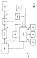
- FIG. 1 an automated fluid pressure control system 10 which provides a fluid to a fluid delivery device 12.
- the fluid delivery device 12 may comprise an inflatable balloon having apertures through which the supply fluid is locally administered to a delivery site internal to the body of a patient.
- the delivery site may comprise the walls of a blood vessel.
- a reservoir 14 containing the fluid to be delivered is connected to the delivery device 12 by a conduit 16, such as a lumen of a catheter.
- a driver 18 provides pressure to move the fluid from the reservoir 14 through the catheter 16 to the delivery device 12.
- the pressure provided by the driver 18 is selected to maintain the balloon in the inflated state and force the fluid through the apertures of the balloon into the vessel walls.
- the pressure is maintained high enough so that the fluid leaving the balloon will only be administered to the walls of the blood vessel and will not flow to any significant extent into the bloodstream. At the same time, the pressure is not so high as to cause damage to the vessel.
- the size of the balloon is selected such that when inflated, some pressure will be applied by the balloon to the vessel walls to confine the apertures to intimate contact with those vessel walls. A balloon having a size too small will allow the medical fluid leaving the apertures to be swept away by the bloodstream while a balloon with a size too large may cause damage to the vessel when inflated.
- a pressure sensor 20 in this embodiment senses the pressure in the conduit between the reservoir 14 and the delivery device 12 and provides a sensed pressure signal to a controller 22.
- the controller 22 compares the sensed pressure to a desired administration pressure and outputs an error signal in the event that they differ.
- the error signal is provided to the driver 18 which alters the pressure of the medical fluid to attain the desired administration pressure.
- the driver 18 alters the volume of the reservoir 14 thereby controlling the pressure of the fluid in the system. Because the delivery device 12 permits the outflow of the fluid provided by the reservoir 14, the driver 18 must continually empty the reservoir 14 to maintain the desired administration pressure. In the event that the sensed pressure is less than the desired administration pressure, the rate at which the reservoir 14 is emptied by the driver 18 will be increased to raise the pressure. In the event that the sensed pressure is above the desired administration pressure, the rate at which the reservoir 14 is emptied by the driver 18 will be decreased to lower the pressure.
- the controller 22 may also receive a reverse control signal 24 from an operator in which case the controller 22 will control the driver 18 to stop the flow of the medical fluid.
- the driver may reverse the flow to deflate the balloon and to assure that none of the medical fluid leaves the delivery device 12 during withdrawal from the patient.
- the driver 18 may accomplish this by increasing the volume of the reservoir thereby creating negative pressure.
- a volume detector 26 determines the amount of fluid delivered to the delivery device 12 and provides a volume signal to the controller 22.
- the volume signal is compared by the controller 22 to a signal representing a desired volume to be administered and, in the event that the two are equal, the controller 22 controls the driver 18 to cease delivery of the fluid to the delivery device 12.
- the volume detector 26 may take different forms, one of which is a monitor of the movement of the driver 18. Where certain positions of the driver 18 are correlated with certain volumes of fluid expelled from the reservoir 14, the amount of fluid delivered can be determined from the position of the driver 18.
- the volume detector 26 may also determine the end-of-travel position of the driver 18 and, when the driver reaches that position, may output a signal to the controller 22 which in turn may then automatically control the driver 18 to cease delivery of the fluid.
- a signal to the controller 22 which in turn may then automatically control the driver 18 to cease delivery of the fluid.
- the controller 22 compares the pressure sensed by pressure sensor 20 to the volume of fluid delivered as detected by the volume detector 26. In the event that the rate of fluid delivered remains the same but the pressure sensed decreases below a predetermined minimum, for example two atmospheres, and stays at that predetermined pressure for a selected period of time, for example two seconds, the controller 22 will provide a delivery alarm 28.
- This delivery alarm 28 is intended to indicate a fluid delivery problem.
- the controller 22 monitors the time of the delivery of the fluid from the reservoir 14. Upon receiving from the pressure sensor 20 an indication that the desired administration pressure has been reached, the controller 22 may then begin to time the administration of the fluid to the delivery site and upon reaching the time limit, provide a time alarm 30 and/or cause the driver 18 to cease delivery.
- the predetermined time limit may be set at a safe period of blood flow interruption so as not to harm the patient, for example, ninety seconds.
- the controller 22 may automatically issue the time alarm 30 and automatically control the driver 18 to deflate the balloon.
- the controller 22 may also include a maximum pressure limit. In the event that the pressure exceeds that limit, the controller 22 will provide a pressure alarm 32 and immediately lower the pressure such as by controlling the driver 18 to cease operation. For example, a pressure limit of 0.81MPa (eight atmospheres) may be input to the controller 22. If the pressure of the fluid should exceed 0.81MPa (eight atmospheres), delivery would be immediately stopped and the pressure alarm 32 provided.
- a pressure limit of 0.81MPa (eight atmospheres) may be input to the controller 22. If the pressure of the fluid should exceed 0.81MPa (eight atmospheres), delivery would be immediately stopped and the pressure alarm 32 provided.
- the desired administration pressure, pressure alarm limit and time alarm limit may be set into the controller 22 via front panel controls 34, a keyboard or other means.
- the front panel may also contain a switch for reverse drive 24 of the driver 18 to accomplish deflation of the delivery device 12, when delivery device 12 is an inflatable balloon fitted with apertures.
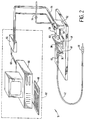
- the reservoir takes the form of a syringe 36 and the syringe plunger 38 operates to vary the volume of the syringe 36 by moving farther into or out of the syringe barrel.
- the syringe barrel is rigidly mounted by means of a mounting member 40.
- a dilatation catheter 42 is connected to the output port 44 of the syringe and has a dilatation balloon 46 mounted at its distal end.
- the driver comprises in this case a slide mechanism 48 coupled to the syringe plunger 38 for moving the syringe plunger 38 in relation to the syringe barrel, an air cylinder 50 and an air controller 52 comprising a solenoid valve (not shown) and a control circuit (not shown).
- a pneumatic power source in this case a source of air pressure, is supplied to the air controller 52 via an input line 54.
- the air controller 52 receives the air pressure from the air pressure line 54 and controls that air pressure in accordance with the desired administration pressure set into the air controller 52 along electrical line 56.
- the air controller 52 comprises an electro-pneumatic regulator having the model designation of "QB" and manufactured by Proportion-Air, Inc. of McCordsville, Indiana.
- This particular regulator incorporates a closed loop pressure control system where the pressure output of the regulator is sensed by a pressure transducer and is compared to the pressure signal set in the electronic control circuit of the regulator. In the event that a difference is sensed between the two pressures, the internal control circuit of the regulator changes the pressure output.
- the output pressure from the regulator is coupled to the air cylinder 50 which applies force against the syringe plunger 38 to move it relative to the syringe barrel thereby affecting the pressure of the fluid in the syringe. Because of this direct physical link, the pressure sensed at the output of the regulator 52 is therefore indicative of the pressure of the fluid in the syringe 36.
- the solenoid valve (not shown) of the air controller 52 may be switched to port the output air pressure from the regulator to one side or the other of the air cylinder to cause the syringe plunger 38 to either move farther into the syringe barrel or more farther out of the syringe barrel.
- a displacement detector 58 is also shown in FIG. 2 and detects the position of the slide mechanism 48.
- the displacement detector 58 comprises a linear resistor having a wiping contact connected to a linkage 60 which is connected to the slide mechanism 48 for moving the syringe plunger 38.
- the wiping contact varies the voltage across the linear resistor 58 in dependence upon the position of the slide mechanism 48. Because the slide mechanism 48 is directly connected to the syringe plunger, the position of the slide mechanism 48 corresponds to the position of the syringe plunger 38. Thus, the amount of fluid provided from the syringe 36 can be determined by the voltage of the linear resistor 58.
- the controller 62 of FIG. 2 comprises two main parts, an interface unit 64 which comprises an analog-to-digital converter (A-to-D converter) and a digital-to-analog converter (D-to-A converter), a bus 63, and a processor 66.
- the processor 66 in this case comprises a micro-computer but may comprise other types of processors.
- the output signal of the linear resistor 58 is analog in form and is provided to the interface unit 64 for conversion to a digital signal before forwarding it on to the processor 66.
- the desired delivery pressure of the syringe fluid is input in the processor 66 through the keyboard 68 in this case.
- the processor 66 provides a digital output signal representative of the pressure which is converted to an analog signal by the interface unit 64.
- That analog pressure signal is provided to the electro-pneumatic regulator 52 to control the air cylinder 50 and the slide mechanism 48.
- the pressure controller would include the main controller 62 which provides the control signal for the desired pressure and also the pressure controller which is built into the QB electro-pneumatic regulator.
- An A-to-D converter found usable is the DASCON-1, from Metabyte, Inc. which is a twelve-bit converter, although other converters may be used.
- a displacement detector which may be used is the LT-103 from Waters Manufacturing.
- the processor program is executed at step 69 and the syringe size is input at step 70 and either a full stroke delivery or a measured volume delivery is selected at step 72 as the operation mode.
- the desired administration pressure P input , the delivery volume V input , and the maximum time of inflation T input are entered at step 74, although a default time value such as ninety seconds may be used.
- the processor 66 converts the delivery pressure P input to the pressure to be provided by the regulator 52 P reg .
- the processor 66 also converts the delivery volume V input to plunger travel distance d input according to the syringe size.
- step 80 the air cylinder 50 is vented, at step 82 the solenoid is activated and, at step 84 the syringe and slide mechanism 48 are manually aligned with the syringe plunger 38 being engaged.
- the delivery sequence is initiated at step 86 and the starting voltage from the linear resistor 58 is read at step 88 as the zero travel distance.
- the timer is started at step 90 and the pressure P reg to be maintained by the regulator 52 is sent to the regulator.
- step 94 the travel distance "d" of the slide mechanism 48 and the time "t" are continually monitored.
- the volume of fluid to be administered may be entered by means of a cassette identifier. Entry of the cassette identifier will inform the processor 66 of the end-of-travel position for that particular cassette and may also include the maximum pressure P max permitted with that cassette. This information may be provided by means of a bar code placed on the cassette which may be read by a bar code reader (not shown) attached to the processor 66.
- a bar code reader (not shown) attached to the processor 66.
- the cassette referred to may take the form of a syringe or other device which performs the function of a fluid reservoir.
- a look-up table containing information corresponding to each of the possible cassettes usable in the system may be included with the processor 66.
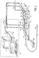
- FIG. 4 a second embodiment of an automated fluid pressure control system is presented.
- a fluid reservoir comprising a syringe 36 and a pneumatic driver for moving the syringe plunger 38 are used to control the pressure of the fluid in the syringe 36.
- the fluid is forced out of the syringe 36, into the catheter 42 and into the delivery device which, in this case, is an inflatable balloon 46.
- the system of FIG. 4 also includes a pressure sensor 102 for monitoring the pressure of the fluid.
- the pressure sensor 102 may take the form of a silicon piezo-resistor which is responsive to the pressure of the fluid between the output port 44 of the syringe 36 and the catheter 42.
- a commonly available pressure sensor is the MPX-700D from Motorola.
- the pressure sensed is provided to the interface unit 64 on line 104 for conversion to a digital signal and for forwarding to the processor 66. Additionally, a pressure display 106 is provided for monitoring the pressure of the fluid being delivered.
- the processor 66 compares the digital pressure signal to the desired administration pressure and outputs on the bus 63 an error signal.
- the interface unit 64 converts that digital error signal to an analog signal for forwarding to the air pressure controller 52.
- a pressure regulator such as the QB electro-pneumatic regulator which converts the input signal to a pressure
- the error signal must be added to or subtracted from the desired pressure signal provided to the regulator.
- the pressure regulator 52 itself monitors its own output while the additional pressure sensor 102 mounted at the output of the syringe 36 also monitors pressure.
- a further feature incorporated in the system of FIG. 4 is an air-in-line sensor 108 for detecting air bubbles.
- the output of the air-in-line sensor is transmitted on line 110 to the interface unit 64 for conversion to a digital signal and is then transmitted to the processor 66.
- the processor 66 may stop delivery of the fluid by the pneumatic driver and provide an alarm.
- Such air-in-line sensors are available from Zevex, Inc. in Murray, Utah. Alarms, such as those for air-in-line and pressure, may be provided by a display 114 connected to the processor 66 and may also be given audibly.
- Known techniques for increasing the accuracy of the volume detection of fluid delivered to the delivery device 46 may be employed. For example, slope, offset and scale factors may be stored and made available to the processor 66 for each displacement detector 58 used. Different syringes or cassettes may be used with the system, each of which has a look-up table made available to the processor 66. Techniques other than look-up tables may be used such as interpolation between beginning-of-travel and end-of-travel points. The operator may be prompted for a cassette code and upon entering that code, the processor may then create a look-up table for that cassette based on characteristic data of the cassette previously stored.
- Processing techniques for smoothing pneumatic driver 50 and regulator 52 responses may be included in the processor 66.
- a classical proportional, integral, derivative control system may be used.
- the processor program is executed at step 69, and the syringe size is input at step 70.
- step 72 either a full stroke delivery or a measured volume delivery operational mode is selected.
- the desired administration pressure P input , the maximum pressure P max , the delivery volume V input , and the maximum time of inflation T input are entered at step 74, although a default time value such as ninety seconds may be used.
- the processor 66 converts the delivery pressure P input to the pressure to P reg , the pressure to be provided by the regulator 52.
- the processor 66 converts the delivery volume V input to plunger travel distance d input according to the syringe size.
- the air cylinder 50 is vented, at step 82, the solenoid is activated, and at step 84 the syringe and slide mechanism 48 are manually aligned with the syringe plunger 38 being engaged.
- the delivery sequence is initiated at step 86 and the starting voltage from the linear resistor 58 is read at step 88 as the zero travel distance.
- the timer is started and at step 92 the pressure P reg to be maintained by the regulator 52 is sent to the regulator.
- the timer may be automatically started upon reaching a predetermined minimum pressure, as measured by the pressure sensor 102; for example, 0.20MPa (two atmospheres).
- step 114 the fluid line is monitored for the existence of air and if an unacceptably high amount of air is detected, an alarm is provided at step 116.
- the delivery pressure is continuously monitored during step 118 and if that pressure equals or exceeds P max 120, an alarm is provided at step 116. If, at step 122, the delivery pressure is not equal to P input , the delivery pressure is increased or decreased at step 124 until P input is reached.
- step 94 the travel distance of the slide mechanism 48 is continually monitored and, at step 96 when either the distance traveled "d" equals d input or the time expired "t" equals t input , the timer is stopped at step 98 and the cylinder retracted at step 100 to allow removal or further disposition of the catheter 42.
- An end-of-travel determination of the syringe plunger may be made in the above embodiment.
- the end of travel displacement may be programmed into the processor 66 as a characteristic of each cassette used. This data may reside in a look-up table in the processor or be input to the processor 66 in other ways.
- the displacement sensor may be monitored for change and in the event that no further change occurs, the end of travel of the syringe plunger may be assumed. In the case of FIGS. 3 and 5 where at step 72 a selection of full stroke delivery or measured volume delivery is required, the full stroke delivery may be determined by end of travel.
- a higher initial pressure may be programmed into the processor 66 for starting the fluid delivery. This initial pressure would be greater than P input and would cause rapid inflation of the delivery device so that a minimum loss of inflation fluid occurs. After inflating, the pressure would then be reduced to P input .
- a pneumatic power source typically available in most hospital rooms is the 0.69MPa (100 psi) air provided at a wall fitting.
- a connecting hose 54 may be coupled between the wall fitting and the air pressure controller 52 to provide a pneumatic energy source for the air cylinder 50.
- the use of pneumatic power rather than electrical power to pressurize the delivery fluid reduces the electrical hazard to the patient.
- a pneumatic system provided the needed ramp-up speed to quickly inflate the balloon with the fluid to be administered while allowing losing only an insignificant amount of the fluid to enter the bloodstream during inflation.
- Other driver systems may be used, such as a motor system using a stepper motor.
- a pneumatic system offered a cost effective system which may be contained in a relatively small and light weight case. Pneumatic energy is readily available in most hospital rooms; hence, no portable source of power, such as an air cylinder, need be included in one embodiment. In another embodiment where air pressure is not available from the room, a portable air cylinder may be used. The embodiment using pneumatic power provides a rapid response and accurate control. In the case where a stepper motor is used to provide the driving means, a more complex, heavier and more expensive system may result because of the addition of the stepper motor itself.
- the driver 18 may take forms other than a volume controller of the reservoir 14. A device which draws the fluid from the reservoir without varying the volume of the reservoir may be used.
- FIGS. 1-5 are not limited to applications involving only the blood vessels. They may be used in procedures with organs such as the kidney, the liver; and used in other procedures such as with the prostate and in other ducts.
Landscapes
- Health & Medical Sciences (AREA)
- Life Sciences & Earth Sciences (AREA)
- Heart & Thoracic Surgery (AREA)
- Biomedical Technology (AREA)
- Animal Behavior & Ethology (AREA)
- Pulmonology (AREA)
- Engineering & Computer Science (AREA)
- Anesthesiology (AREA)
- Child & Adolescent Psychology (AREA)
- Hematology (AREA)
- Biophysics (AREA)
- General Health & Medical Sciences (AREA)
- Public Health (AREA)
- Veterinary Medicine (AREA)
- Infusion, Injection, And Reservoir Apparatuses (AREA)
- Media Introduction/Drainage Providing Device (AREA)
- Control Of Fluid Pressure (AREA)
Applications Claiming Priority (3)
| Application Number | Priority Date | Filing Date | Title |
|---|---|---|---|
| US07/923,063 US5342298A (en) | 1992-07-31 | 1992-07-31 | Automated fluid pressure control system |
| US923063 | 1992-07-31 | ||
| EP93440057A EP0581708B1 (fr) | 1992-07-31 | 1993-07-26 | Système de commande pour pression de fluide automatisé |
Related Parent Applications (1)
| Application Number | Title | Priority Date | Filing Date |
|---|---|---|---|
| EP93440057A Division EP0581708B1 (fr) | 1992-07-31 | 1993-07-26 | Système de commande pour pression de fluide automatisé |
Publications (2)
| Publication Number | Publication Date |
|---|---|
| EP0824934A2 true EP0824934A2 (fr) | 1998-02-25 |
| EP0824934A3 EP0824934A3 (fr) | 1999-05-19 |
Family
ID=25448057
Family Applications (3)
| Application Number | Title | Priority Date | Filing Date |
|---|---|---|---|
| EP97113492A Withdrawn EP0824934A3 (fr) | 1992-07-31 | 1993-07-26 | Systéme de commande automatisépour pression de fluide |
| EP93440057A Expired - Lifetime EP0581708B1 (fr) | 1992-07-31 | 1993-07-26 | Système de commande pour pression de fluide automatisé |
| EP97113486A Withdrawn EP0824933A3 (fr) | 1992-07-31 | 1993-07-26 | Système de commande automatisé pour pression de fluide |
Family Applications After (2)
| Application Number | Title | Priority Date | Filing Date |
|---|---|---|---|
| EP93440057A Expired - Lifetime EP0581708B1 (fr) | 1992-07-31 | 1993-07-26 | Système de commande pour pression de fluide automatisé |
| EP97113486A Withdrawn EP0824933A3 (fr) | 1992-07-31 | 1993-07-26 | Système de commande automatisé pour pression de fluide |
Country Status (5)
| Country | Link |
|---|---|
| US (1) | US5342298A (fr) |
| EP (3) | EP0824934A3 (fr) |
| JP (1) | JPH06319797A (fr) |
| CA (1) | CA2101113A1 (fr) |
| DE (1) | DE69315006T2 (fr) |
Families Citing this family (207)
| Publication number | Priority date | Publication date | Assignee | Title |
|---|---|---|---|---|
| US6402718B1 (en) | 1992-08-17 | 2002-06-11 | Medrad, Inc. | Front-loading medical injector and syringe for use therewith |
| US5383858B1 (en) | 1992-08-17 | 1996-10-29 | Medrad Inc | Front-loading medical injector and syringe for use therewith |
| DE69329774T2 (de) * | 1992-10-15 | 2001-06-21 | Baxter International Inc., Deerfield | Infusionspumpe mit elektronisch ladbarer medikamentenbibliothek |
| DE4310808C2 (de) * | 1993-04-02 | 1995-06-22 | Boehringer Mannheim Gmbh | System zur Dosierung von Flüssigkeiten |
| US6203759B1 (en) | 1996-05-31 | 2001-03-20 | Packard Instrument Company | Microvolume liquid handling system |
| US6537817B1 (en) | 1993-05-31 | 2003-03-25 | Packard Instrument Company | Piezoelectric-drop-on-demand technology |
| US6521187B1 (en) | 1996-05-31 | 2003-02-18 | Packard Instrument Company | Dispensing liquid drops onto porous brittle substrates |
| CA2129284C (fr) * | 1993-11-24 | 1999-03-09 | Kenneth J. Niehoff | Regulation de l'entrainement du plongeur pour l'injection de liquides a des animaux |
| US5494036A (en) * | 1993-11-26 | 1996-02-27 | Medrad, Inc. | Patient infusion system for use with MRI |
| IL109669A (en) * | 1994-05-17 | 1997-09-30 | Hadasit Med Res Service | System and method for coronary angioplasty |
| US6405732B1 (en) * | 1994-06-24 | 2002-06-18 | Curon Medical, Inc. | Method to treat gastric reflux via the detection and ablation of gastro-esophageal nerves and receptors |
| US5882343A (en) * | 1995-04-20 | 1999-03-16 | Invasatec, Inc. | Dual port syringe |
| US7267666B1 (en) * | 1995-04-20 | 2007-09-11 | Acist Medical Systems, Inc. | Angiographic injector system with multiple processor redundancy |
| US6099502A (en) * | 1995-04-20 | 2000-08-08 | Acist Medical Systems, Inc. | Dual port syringe |
| US6221045B1 (en) * | 1995-04-20 | 2001-04-24 | Acist Medical Systems, Inc. | Angiographic injector system with automatic high/low pressure switching |
| EP1920718A1 (fr) * | 1995-04-20 | 2008-05-14 | ACIST Medical Systems, Inc. | Injecteur de produit de contraste radiographique |
| US6656157B1 (en) | 1995-04-20 | 2003-12-02 | Acist Medical Systems, Inc. | Infinitely refillable syringe |
| US5979453A (en) * | 1995-11-09 | 1999-11-09 | Femrx, Inc. | Needle myolysis system for uterine fibriods |
| US5833682A (en) * | 1996-08-26 | 1998-11-10 | Illumenex Corporation | Light delivery system with blood flushing capability |
| US5876378A (en) * | 1996-09-20 | 1999-03-02 | Mbadugha; Joseph O. | Apparatus and method for injecting liquids into patients |
| IL121214A0 (en) * | 1997-06-17 | 1998-01-04 | Medicard Ltd | Angioplasty pressure/volume control system |
| USD412205S (en) | 1997-07-29 | 1999-07-20 | Invasatec, Inc. | Dual port syringe |
| AU736989B2 (en) * | 1997-10-27 | 2001-08-09 | Illumenex Corporation | Light delivery system with blood flushing capability |
| US6200289B1 (en) * | 1998-04-10 | 2001-03-13 | Milestone Scientific, Inc. | Pressure/force computer controlled drug delivery system and the like |
| US6585684B1 (en) | 1998-12-22 | 2003-07-01 | Novoste Corporation | Automated system for the radiation treatment of a desired area within the body of a patient |
| US6958053B1 (en) | 1999-11-24 | 2005-10-25 | Medrad, Inc. | Injector providing drive member advancement and engagement with syringe plunger, and method of connecting a syringe to an injector |
| KR100577410B1 (ko) * | 1999-11-30 | 2006-05-08 | 엘지.필립스 엘시디 주식회사 | 엑스레이 영상 감지소자 및 그 제조방법 |
| US7645258B2 (en) | 1999-12-01 | 2010-01-12 | B. Braun Medical, Inc. | Patient medication IV delivery pump with wireless communication to a hospital information management system |
| WO2001041862A1 (fr) * | 1999-12-09 | 2001-06-14 | The Research Foundation Of State University Of New York | Dispositif d'application de gaz regule conçu pour angioscopie en colonne de gaz |
| US6497680B1 (en) * | 1999-12-17 | 2002-12-24 | Abbott Laboratories | Method for compensating for pressure differences across valves in cassette type IV pump |
| US6652489B2 (en) | 2000-02-07 | 2003-11-25 | Medrad, Inc. | Front-loading medical injector and syringes, syringe interfaces, syringe adapters and syringe plungers for use therewith |
| US6626862B1 (en) | 2000-04-04 | 2003-09-30 | Acist Medical Systems, Inc. | Fluid management and component detection system |
| GB0011052D0 (en) * | 2000-05-09 | 2000-06-28 | Hudson John O | Medical device and use thereof |
| GB0011053D0 (en) * | 2000-05-09 | 2000-06-28 | Hudson John O | Medical device and use thereof |
| DE20008961U1 (de) * | 2000-05-18 | 2001-09-27 | B. Braun Melsungen Ag, 34212 Melsungen | Infusionspumpe |
| US6704592B1 (en) | 2000-06-02 | 2004-03-09 | Medrad, Inc. | Communication systems for use with magnetic resonance imaging systems |
| AUPQ867900A0 (en) | 2000-07-10 | 2000-08-03 | Medrad, Inc. | Medical injector system |
| US6685668B1 (en) * | 2000-07-31 | 2004-02-03 | Abbott Laboratories | Closed-loop IV fluid flow control |
| ES2205956B1 (es) * | 2000-10-16 | 2005-04-01 | Probitas Pharma S.A. | Aparato para inflado y desinflado de cateteres con balon y procedimiento de utilizacion del mismo. |
| GB0030794D0 (en) * | 2000-12-16 | 2001-01-31 | Hudson John O | Medical device and use thereof |
| GB2371754B (en) * | 2001-02-02 | 2005-09-21 | Biocompatibles Ltd | Balloon catheter inflation |
| US20020143294A1 (en) | 2001-02-14 | 2002-10-03 | Duchon Douglas J. | Catheter fluid control system |
| US6699243B2 (en) | 2001-09-19 | 2004-03-02 | Curon Medical, Inc. | Devices, systems and methods for treating tissue regions of the body |
| US7004899B2 (en) * | 2001-06-29 | 2006-02-28 | Ethicon, Inc. | System and method for assessing urinary function |
| JP2005511111A (ja) * | 2001-06-29 | 2005-04-28 | エシコン・インコーポレイテッド | 排尿機能を評価するためのシステム及び方法 |
| US20030050648A1 (en) | 2001-09-11 | 2003-03-13 | Spiration, Inc. | Removable lung reduction devices, systems, and methods |
| US20060155261A1 (en) * | 2001-09-19 | 2006-07-13 | Curon Medical, Inc. | Systems and methods for treating tissue regions of the body |
| US7615049B2 (en) | 2001-09-19 | 2009-11-10 | Mederi Therapeutics, Inc. | Devices, systems and methods for treating tissue regions of the body |
| US6592594B2 (en) | 2001-10-25 | 2003-07-15 | Spiration, Inc. | Bronchial obstruction device deployment system and method |
| DE10154163A1 (de) | 2001-11-03 | 2003-05-22 | Advanced Med Tech | Vorrichtung zum Aufrichten und Stabilisieren der Wirbelsäule |
| US6929637B2 (en) | 2002-02-21 | 2005-08-16 | Spiration, Inc. | Device and method for intra-bronchial provision of a therapeutic agent |
| US6692457B2 (en) * | 2002-03-01 | 2004-02-17 | Insulet Corporation | Flow condition sensor assembly for patient infusion device |
| US20030216769A1 (en) | 2002-05-17 | 2003-11-20 | Dillard David H. | Removable anchored lung volume reduction devices and methods |
| US20030181922A1 (en) | 2002-03-20 | 2003-09-25 | Spiration, Inc. | Removable anchored lung volume reduction devices and methods |
| US6780170B2 (en) * | 2002-05-15 | 2004-08-24 | Liebel-Flarsheim Company | Hydraulic remote for a medical fluid injector |
| US7553294B2 (en) | 2002-05-30 | 2009-06-30 | Medrad, Inc. | Syringe plunger sensing mechanism for a medical injector |
| US20040059263A1 (en) * | 2002-09-24 | 2004-03-25 | Spiration, Inc. | Device and method for measuring the diameter of an air passageway |
| US20040010209A1 (en) * | 2002-07-15 | 2004-01-15 | Spiration, Inc. | Device and method for measuring the diameter of an air passageway |
| US6893414B2 (en) * | 2002-08-12 | 2005-05-17 | Breg, Inc. | Integrated infusion and aspiration system and method |
| US20060135940A1 (en) * | 2003-01-06 | 2006-06-22 | The Trustees Of Columbia | Programmed pulsed infusion methods and devices |
| US20060047261A1 (en) * | 2004-06-28 | 2006-03-02 | Shailendra Joshi | Intra-arterial catheter for drug delivery |
| WO2004087237A2 (fr) * | 2003-03-27 | 2004-10-14 | Medical Research Products-A, Inc. | Dispositif implantable de distribution de medicament faisant intervenir un regulateur de pression |
| US7100616B2 (en) | 2003-04-08 | 2006-09-05 | Spiration, Inc. | Bronchoscopic lung volume reduction method |
| DE20307256U1 (de) * | 2003-05-09 | 2003-10-02 | Lifebridge Medizintechnik GmbH, 85646 Neufarn | Tragbare Herzlungenmaschine |
| US6813964B1 (en) * | 2003-05-21 | 2004-11-09 | Hospira, Inc. | Fluid flow measurement device |
| US7419478B1 (en) | 2003-06-25 | 2008-09-02 | Medrad, Inc. | Front-loading syringe for medical injector having a flexible syringe retaining ring |
| US7533671B2 (en) | 2003-08-08 | 2009-05-19 | Spiration, Inc. | Bronchoscopic repair of air leaks in a lung |
| US7320676B2 (en) * | 2003-10-02 | 2008-01-22 | Medtronic, Inc. | Pressure sensing in implantable medical devices |
| US9033920B2 (en) * | 2003-10-02 | 2015-05-19 | Medtronic, Inc. | Determining catheter status |
| US8323244B2 (en) * | 2007-03-30 | 2012-12-04 | Medtronic, Inc. | Catheter malfunction determinations using physiologic pressure |
| US9138537B2 (en) | 2003-10-02 | 2015-09-22 | Medtronic, Inc. | Determining catheter status |
| US8317770B2 (en) * | 2006-04-06 | 2012-11-27 | Medtronic, Inc. | Systems and methods of identifying catheter malfunctions using pressure sensing |
| US7022116B2 (en) * | 2003-10-23 | 2006-04-04 | Medtronic, Inc. | Method for monitoring bolus delivery |
| US7666169B2 (en) | 2003-11-25 | 2010-02-23 | Medrad, Inc. | Syringe and syringe plungers for use with medical injectors |
| USD1031029S1 (en) | 2003-11-25 | 2024-06-11 | Bayer Healthcare Llc | Syringe plunger |
| JP4756851B2 (ja) * | 2004-03-19 | 2011-08-24 | オリンパス株式会社 | 内視鏡バルーン制御装置 |
| US20050209602A1 (en) * | 2004-03-22 | 2005-09-22 | Disc Dynamics, Inc. | Multi-stage biomaterial injection system for spinal implants |
| US8491636B2 (en) | 2004-03-23 | 2013-07-23 | Medtronic Cryopath LP | Method and apparatus for inflating and deflating balloon catheters |
| US7727228B2 (en) | 2004-03-23 | 2010-06-01 | Medtronic Cryocath Lp | Method and apparatus for inflating and deflating balloon catheters |
| US20060129087A1 (en) * | 2004-03-31 | 2006-06-15 | Takefumi Uesugi | Method and apparatus for supplying predetermined gas into body cavities of a patient |
| US7513884B2 (en) * | 2004-04-22 | 2009-04-07 | Medtronic, Inc. | Branching catheter systems with diagnostic components |
| US7217251B2 (en) * | 2004-04-22 | 2007-05-15 | Medtronic, Inc. | Pressure relief methods in a medical catheter system |
| JP3834820B2 (ja) * | 2004-11-04 | 2006-10-18 | フジノン株式会社 | 内視鏡装置用のバルーン制御装置 |
| EP1707958B1 (fr) * | 2005-03-31 | 2011-01-19 | Agilent Technologies, Inc. | Dispositif et procédé pour fournir un solvant avec correction du mouvement du piston |
| US20060276744A1 (en) * | 2005-05-20 | 2006-12-07 | Falk Theodore J | Configuration for drug delivery systems |
| US20070003528A1 (en) | 2005-06-29 | 2007-01-04 | Paul Consigny | Intracoronary device and method of use thereof |
| WO2007076463A2 (fr) | 2005-12-27 | 2007-07-05 | Acist Medical Systems, Inc. | Dispositif de gonflement de ballonnet |
| US20070213656A1 (en) * | 2006-03-08 | 2007-09-13 | Arthur Ferdinand | Device for outputting a qualitative indication associated with the inflation of an expandable member |
| US8926569B2 (en) | 2006-03-15 | 2015-01-06 | Bayer Medical Care Inc. | Plunger covers and plungers for use in syringes and methods of fabricating plunger covers and plungers for use in syringes |
| US7691151B2 (en) | 2006-03-31 | 2010-04-06 | Spiration, Inc. | Articulable Anchor |
| US20070255286A1 (en) * | 2006-04-27 | 2007-11-01 | Sdgi Holdings, Inc. | Devices, apparatus, and methods for improved disc augmentation |
| US8133279B2 (en) * | 2006-04-27 | 2012-03-13 | Warsaw Orthopedic, Inc. | Methods for treating an annulus defect of an intervertebral disc |
| US20070255406A1 (en) * | 2006-04-27 | 2007-11-01 | Sdgi Holdings, Inc. | Devices, apparatus, and methods for bilateral approach to disc augmentation |
| US20080077225A1 (en) * | 2006-09-22 | 2008-03-27 | Carlin Donald B | Accuracy lumen sizing and stent expansion |
| US7744559B2 (en) | 2006-12-19 | 2010-06-29 | Cytyc Corporation | Systems and methods for drug infusion with feedback control |
| USD942005S1 (en) | 2007-03-14 | 2022-01-25 | Bayer Healthcare Llc | Orange syringe plunger cover |
| USD847985S1 (en) | 2007-03-14 | 2019-05-07 | Bayer Healthcare Llc | Syringe plunger cover |
| USD1002840S1 (en) | 2007-03-14 | 2023-10-24 | Bayer Healthcare Llc | Syringe plunger |
| US9044537B2 (en) | 2007-03-30 | 2015-06-02 | Medtronic, Inc. | Devices and methods for detecting catheter complications |
| US8417311B2 (en) | 2008-09-12 | 2013-04-09 | Optiscan Biomedical Corporation | Fluid component analysis system and method for glucose monitoring and control |
| US7981078B2 (en) * | 2007-07-09 | 2011-07-19 | Mego Afek Ac Ltd. | Inflation/deflation system for a catheter |
| KR100896797B1 (ko) * | 2007-09-14 | 2009-05-11 | 정선근 | 생물체 내 액상 물질 주입 장치 및 주입 방법 |
| US20090076439A1 (en) * | 2007-09-14 | 2009-03-19 | Dollar Michael L | Inflation System for Balloon Catheter |
| CA2702116C (fr) | 2007-10-10 | 2021-01-05 | Optiscan Biomedical Corporation | Systeme d'analyse de composant de fluide et procede pour controler et reguler le glucose |
| JP5570993B2 (ja) | 2007-10-12 | 2014-08-13 | スピレーション インコーポレイテッド | 弁装填具の方法、システム、および装置 |
| US8043301B2 (en) | 2007-10-12 | 2011-10-25 | Spiration, Inc. | Valve loader method, system, and apparatus |
| US8556949B2 (en) | 2007-11-14 | 2013-10-15 | DePuy Synthes Products, LLC | Hybrid bone fixation element and methods of using the same |
| US8517990B2 (en) | 2007-12-18 | 2013-08-27 | Hospira, Inc. | User interface improvements for medical devices |
| EP2231230A4 (fr) * | 2007-12-21 | 2013-01-23 | Carticept Medical Inc | Système d'injection articulaire |
| US7959598B2 (en) | 2008-08-20 | 2011-06-14 | Asante Solutions, Inc. | Infusion pump systems and methods |
| WO2010090858A2 (fr) * | 2009-01-21 | 2010-08-12 | Medtronic, Inc. | Systèmes cathéters comportant des réducteurs de débit |
| DK2241344T3 (en) | 2009-04-16 | 2014-03-03 | Hoffmann La Roche | Portable infusion with feel-testing device |
| US20110082450A1 (en) * | 2009-10-02 | 2011-04-07 | Cardiofocus, Inc. | Cardiac ablation system with inflatable member having multiple inflation settings |
| ES2401571T3 (es) * | 2010-02-09 | 2013-04-22 | Sanofi-Aventis Deutschland Gmbh | Dispositivo médico para la administración local de fármacos |
| EP2353501A1 (fr) * | 2010-02-09 | 2011-08-10 | Sanofi-Aventis Deutschland GmbH | Dispositif de post-conditionnement contrôlé d'informatique |
| CA2736841C (fr) | 2010-04-15 | 2014-02-18 | Teneo Innovations Inc. | Dispositif et dispositif de commande electronique pour la commande d'un piston de seringue |
| CA2799775C (fr) | 2010-06-04 | 2020-03-24 | Medrad, Inc. | Systeme et procede pour la planification et le controle d'utilisation de produits pharmaco-radioactifs a doses multiples sur des injecteurs de produits pharmaco-radioactifs |
| US8795241B2 (en) | 2011-05-13 | 2014-08-05 | Spiration, Inc. | Deployment catheter |
| CA2844807C (fr) | 2011-08-19 | 2022-07-26 | Hospira, Inc. | Systemes et procedes pour une interface graphique comprenant une representation graphique de donnees medicales |
| ITRM20110479A1 (it) * | 2011-09-09 | 2013-03-10 | O P A Medical S R L | Gruppo per interventi di cifoplastica |
| WO2013090709A1 (fr) | 2011-12-16 | 2013-06-20 | Hospira, Inc. | Système permettant de surveiller et d'administrer un médicament à un patient et méthode l'utilisant pour réduire les risques associés à une thérapie automatisée |
| US9155578B2 (en) | 2012-02-28 | 2015-10-13 | DePuy Synthes Products, Inc. | Expandable fastener |
| JP6306566B2 (ja) | 2012-03-30 | 2018-04-04 | アイシーユー・メディカル・インコーポレーテッド | 注入システムのポンプ内の空気を検出するための空気検出システムおよび方法 |
| EP3586891B1 (fr) | 2012-07-31 | 2025-04-09 | ICU Medical, Inc. | Système de soins aux patients pour médicaments critiques |
| US9174003B2 (en) | 2012-09-28 | 2015-11-03 | Bayer Medical Care Inc. | Quick release plunger |
| US9539382B2 (en) | 2013-03-12 | 2017-01-10 | Medtronic, Inc. | Stepped catheters with flow restrictors and infusion systems using the same |
| AU2014268355B2 (en) | 2013-05-24 | 2018-06-14 | Icu Medical, Inc. | Multi-sensor infusion system for detecting air or an occlusion in the infusion system |
| CA2913915C (fr) | 2013-05-29 | 2022-03-29 | Hospira, Inc. | Systeme de perfusion qui emploie un ou plusieurs capteurs et des informations additionnelles pour faire une determination d'air concernant le systeme de perfusion |
| ES2845748T3 (es) | 2013-05-29 | 2021-07-27 | Icu Medical Inc | Sistema de infusión y método de uso que impiden la sobresaturación de un convertidor analógico-digital |
| US9561324B2 (en) | 2013-07-19 | 2017-02-07 | Bigfoot Biomedical, Inc. | Infusion pump system and method |
| GB2523989B (en) | 2014-01-30 | 2020-07-29 | Insulet Netherlands B V | Therapeutic product delivery system and method of pairing |
| WO2015131108A2 (fr) | 2014-02-28 | 2015-09-03 | Hospira, Inc. | Système de perfusion et procédé qui utilise la détection optique de bulles d'air à double longueur d'onde |
| WO2015142995A1 (fr) | 2014-03-19 | 2015-09-24 | Bayer Medical Care Inc. | Système d'introduction d'une seringue dans un injecteur |
| US11344673B2 (en) | 2014-05-29 | 2022-05-31 | Icu Medical, Inc. | Infusion system and pump with configurable closed loop delivery rate catch-up |
| US20160058985A1 (en) * | 2014-08-29 | 2016-03-03 | Acclarent, Inc. | Automated inflator for balloon dilator |
| US11344668B2 (en) | 2014-12-19 | 2022-05-31 | Icu Medical, Inc. | Infusion system with concurrent TPN/insulin infusion |
| US20160228645A1 (en) * | 2015-02-06 | 2016-08-11 | Carticept Medical, Inc. | Nerve block injection systems and methods |
| CN111905188B (zh) | 2015-02-18 | 2022-07-22 | 英赛罗公司 | 流体输送和输注装置及其使用方法 |
| US10850024B2 (en) | 2015-03-02 | 2020-12-01 | Icu Medical, Inc. | Infusion system, device, and method having advanced infusion features |
| US9480797B1 (en) | 2015-10-28 | 2016-11-01 | Bayer Healthcare Llc | System and method for syringe plunger engagement with an injector |
| WO2017123525A1 (fr) | 2016-01-13 | 2017-07-20 | Bigfoot Biomedical, Inc. | Interface utilisateur pour système de gestion du diabète |
| US10806859B2 (en) | 2016-01-14 | 2020-10-20 | Bigfoot Biomedical, Inc. | Adjusting insulin delivery rates |
| HK1256995A1 (zh) | 2016-01-14 | 2019-10-11 | Bigfoot Biomedical, Inc. | 药物输送设备、系统和方法中的阻塞解决方案 |
| CA3023658C (fr) | 2016-05-13 | 2023-03-07 | Icu Medical, Inc. | Systeme de pompe a perfusion et procede a purge automatique a ligne commune |
| US12383166B2 (en) | 2016-05-23 | 2025-08-12 | Insulet Corporation | Insulin delivery system and methods with risk-based set points |
| AU2017277804B2 (en) | 2016-06-10 | 2022-05-26 | Icu Medical, Inc. | Acoustic flow sensor for continuous medication flow measurements and feedback control of infusion |
| US10765807B2 (en) * | 2016-09-23 | 2020-09-08 | Insulet Corporation | Fluid delivery device with sensor |
| US11096624B2 (en) | 2016-12-12 | 2021-08-24 | Bigfoot Biomedical, Inc. | Alarms and alerts for medication delivery devices and systems |
| WO2018117584A1 (fr) * | 2016-12-19 | 2018-06-28 | 전북대학교산학협력단 | Dispositif d'injection automatique et système d'injection automatique |
| HUE063479T2 (hu) | 2017-01-06 | 2024-01-28 | Bayer Healthcare Llc | Fecskendõ dugattyú dinamikus tömítéssel |
| US10500334B2 (en) | 2017-01-13 | 2019-12-10 | Bigfoot Biomedical, Inc. | System and method for adjusting insulin delivery |
| US11033682B2 (en) | 2017-01-13 | 2021-06-15 | Bigfoot Biomedical, Inc. | Insulin delivery methods, systems and devices |
| US10583250B2 (en) | 2017-01-13 | 2020-03-10 | Bigfoot Biomedical, Inc. | System and method for adjusting insulin delivery |
| US10758675B2 (en) | 2017-01-13 | 2020-09-01 | Bigfoot Biomedical, Inc. | System and method for adjusting insulin delivery |
| EP3568860B1 (fr) | 2017-01-13 | 2025-12-10 | Insulet Corporation | Méthodes, systèmes et dispositifs d'administration d'insuline |
| US10881792B2 (en) | 2017-01-13 | 2021-01-05 | Bigfoot Biomedical, Inc. | System and method for adjusting insulin delivery |
| US10089055B1 (en) | 2017-12-27 | 2018-10-02 | Icu Medical, Inc. | Synchronized display of screen content on networked devices |
| ES2939249T3 (es) | 2018-02-27 | 2023-04-20 | Bayer Healthcare Llc | Mecanismo de acoplamiento de émbolo de jeringa |
| CN108404277A (zh) * | 2018-03-20 | 2018-08-17 | 天津市胸科医院 | 一种引流管自动挤压装置 |
| USD928199S1 (en) | 2018-04-02 | 2021-08-17 | Bigfoot Biomedical, Inc. | Medication delivery device with icons |
| US11565043B2 (en) | 2018-05-04 | 2023-01-31 | Insulet Corporation | Safety constraints for a control algorithm based drug delivery system |
| US12562251B1 (en) | 2018-05-09 | 2026-02-24 | Bigfoot Biomedical, Inc. | Computing architecture for assuring the provenance of medication therapy related parameters, and related systems, methods and devices |
| AU2019347755B2 (en) | 2018-09-28 | 2023-02-02 | Insulet Corporation | Activity mode for artificial pancreas system |
| EP3864668A1 (fr) | 2018-10-11 | 2021-08-18 | Insulet Corporation | Détection d'événement pour système d'administration de médicament |
| USD920343S1 (en) | 2019-01-09 | 2021-05-25 | Bigfoot Biomedical, Inc. | Display screen or portion thereof with graphical user interface associated with insulin delivery |
| KR102363903B1 (ko) * | 2019-09-06 | 2022-02-21 | 오스템임플란트 주식회사 | 확장 디바이스 및 확장기 관리 시스템 |
| US11801344B2 (en) | 2019-09-13 | 2023-10-31 | Insulet Corporation | Blood glucose rate of change modulation of meal and correction insulin bolus quantity |
| US11935637B2 (en) | 2019-09-27 | 2024-03-19 | Insulet Corporation | Onboarding and total daily insulin adaptivity |
| US11278671B2 (en) | 2019-12-04 | 2022-03-22 | Icu Medical, Inc. | Infusion pump with safety sequence keypad |
| EP4069082B1 (fr) | 2019-12-06 | 2024-06-05 | Insulet Corporation | Techniques et dispositifs de fourniture d'adaptabilité et de personnalisation dans le traitement du diabète |
| US11833329B2 (en) | 2019-12-20 | 2023-12-05 | Insulet Corporation | Techniques for improved automatic drug delivery performance using delivery tendencies from past delivery history and use patterns |
| JP7512395B2 (ja) | 2020-01-06 | 2024-07-08 | インスレット コーポレイション | 持続する残差に基づく食事および/または運動行為の予測 |
| EP4100958A1 (fr) | 2020-02-03 | 2022-12-14 | Insulet Corporation | Utilisation d'une logique floue pour prédire un comportement d'utilisateur affectant la glycémie |
| US11551802B2 (en) | 2020-02-11 | 2023-01-10 | Insulet Corporation | Early meal detection and calorie intake detection |
| US11547800B2 (en) | 2020-02-12 | 2023-01-10 | Insulet Corporation | User parameter dependent cost function for personalized reduction of hypoglycemia and/or hyperglycemia in a closed loop artificial pancreas system |
| US11986630B2 (en) | 2020-02-12 | 2024-05-21 | Insulet Corporation | Dual hormone delivery system for reducing impending hypoglycemia and/or hyperglycemia risk |
| US11324889B2 (en) | 2020-02-14 | 2022-05-10 | Insulet Corporation | Compensation for missing readings from a glucose monitor in an automated insulin delivery system |
| US12495994B2 (en) | 2020-02-20 | 2025-12-16 | Insulet Corporation | Meal bolus subcategories in model based insulin therapy |
| US11607493B2 (en) | 2020-04-06 | 2023-03-21 | Insulet Corporation | Initial total daily insulin setting for user onboarding |
| AR122637A1 (es) | 2020-06-18 | 2022-09-28 | Bayer Healthcare Llc | Sistema y método para el acoplamiento del émbolo de la jeringa con un inyector |
| AU2021311443A1 (en) | 2020-07-21 | 2023-03-09 | Icu Medical, Inc. | Fluid transfer devices and methods of use |
| US12121700B2 (en) | 2020-07-22 | 2024-10-22 | Insulet Corporation | Open-loop insulin delivery basal parameters based on insulin delivery records |
| US11684716B2 (en) | 2020-07-31 | 2023-06-27 | Insulet Corporation | Techniques to reduce risk of occlusions in drug delivery systems |
| US12569619B2 (en) | 2020-09-21 | 2026-03-10 | Insulet Corporation | Techniques for determining automated insulin delivery dosages |
| US12115351B2 (en) | 2020-09-30 | 2024-10-15 | Insulet Corporation | Secure wireless communications between a glucose monitor and other devices |
| EP4696344A3 (fr) | 2020-09-30 | 2026-04-15 | Insulet Corporation | Dispositif d'administration de médicament à glucomètre optique intégré |
| US11135360B1 (en) | 2020-12-07 | 2021-10-05 | Icu Medical, Inc. | Concurrent infusion with common line auto flush |
| US11160925B1 (en) | 2021-01-29 | 2021-11-02 | Insulet Corporation | Automatic drug delivery system for delivery of a GLP-1 therapeutic |
| US11904140B2 (en) | 2021-03-10 | 2024-02-20 | Insulet Corporation | Adaptable asymmetric medicament cost component in a control system for medicament delivery |
| EP4305636A1 (fr) | 2021-03-10 | 2024-01-17 | Insulet Corporation | Dispositif d'administration de médicament ayant une composante de coût de niveau d'analyte réglable et par segments pour répondre aux écarts de niveau d'analyte positifs persistants |
| US12592306B2 (en) | 2021-04-28 | 2026-03-31 | Insulet Corporation | Devices and methods for initialization of drug delivery devices using measured analyte sensor information |
| US12496398B2 (en) | 2021-05-28 | 2025-12-16 | Insulet Corporation | Threshold based automatic glucose control response |
| EP4101482A1 (fr) | 2021-06-07 | 2022-12-14 | Insulet Corporation | Prédiction de sécurité d'exercice basée sur les conditions physiologiques |
| US12514980B2 (en) | 2021-06-30 | 2026-01-06 | Insulet Corporation | Adjustment of medicament delivery by a medicament delivery device based on menstrual cycle phase |
| US12521486B2 (en) | 2021-07-16 | 2026-01-13 | Insulet Corporation | Method for modification of insulin delivery during pregnancy in automatic insulin delivery systems |
| EP4398967A4 (fr) | 2021-09-10 | 2025-07-16 | Cardivascular Systems | Systèmes, procédés et dispositifs pour le gonflage et le dégonflage d'un ballonnet d'angioplastie adaptatif |
| US20240374874A1 (en) * | 2021-09-10 | 2024-11-14 | Cardiovascular Systems, Inc. | Drug coated balloon for angioplasty systems with programmed inflation sequences and adaptive monitoring control of inflation sequences |
| WO2023049900A1 (fr) | 2021-09-27 | 2023-03-30 | Insulet Corporation | Techniques permettant l'adaptation de paramètres dans des systèmes d'aide par entrée d'utilisateur |
| US12599716B2 (en) | 2021-10-12 | 2026-04-14 | Icu Medical, Inc. | Intravenous infusion pump with cassette insertion and pump control user interface |
| USD1091564S1 (en) | 2021-10-13 | 2025-09-02 | Icu Medical, Inc. | Display screen or portion thereof with graphical user interface for a medical device |
| CN114081665B (zh) * | 2021-10-22 | 2022-08-26 | 温州医科大学附属眼视光医院 | 一种准确制备超薄角膜内皮植片的压力稳定系统 |
| US11439754B1 (en) | 2021-12-01 | 2022-09-13 | Insulet Corporation | Optimizing embedded formulations for drug delivery |
| CA3241894A1 (fr) | 2021-12-10 | 2023-06-15 | Icu Medical, Inc. | Systemes de melange de fluides medicaux a commande d'ecoulement coordonnee |
| ES1286945Y (es) * | 2022-01-13 | 2022-05-13 | Marin David Martinez | Dispositivo de inflado para angioplastia mediante regulación automática e inteligencia artificial |
| EP4243030A1 (fr) | 2022-03-09 | 2023-09-13 | Insulet Corporation | Ajustement de paramètres d'administration de médicament dans un mode d'administration de médicament en boucle ouverte |
| EP4646726A1 (fr) | 2023-01-06 | 2025-11-12 | Insulet Corporation | Administration de bolus de repas lancée automatiquement ou manuellement avec assouplissement automatique ultérieur des contraintes de sécurité |
| CN117122798A (zh) * | 2023-09-12 | 2023-11-28 | 上海汉通医疗科技有限公司 | 一种精确控制球囊充盈及冷却循环装置 |
Family Cites Families (33)
| Publication number | Priority date | Publication date | Assignee | Title |
|---|---|---|---|---|
| US2865371A (en) * | 1954-10-18 | 1958-12-23 | Dorbecker Narno | Apparatus for rapidly injecting radioopaque liquid under pressure in the technique of selective angiocardiography |
| US3701345A (en) * | 1970-09-29 | 1972-10-31 | Medrad Inc | Angiographic injector equipment |
| US3720199A (en) * | 1971-05-14 | 1973-03-13 | Avco Corp | Safety connector for balloon pump |
| US4332254A (en) * | 1980-11-17 | 1982-06-01 | Advanced Catheter Systems, Inc. | System for filling and inflating and deflating a vascular dilating cathether assembly |
| US4446867A (en) * | 1981-12-31 | 1984-05-08 | Leveen Robert F | Fluid-driven balloon catheter for intima fracture |
| SE438962B (sv) * | 1983-05-18 | 1985-05-28 | Gambro Crafon Ab | System for skoljning av kroppshalighet |
| DE3338758C2 (de) * | 1983-10-21 | 1986-09-11 | Hubert Dipl.-Ing. 1000 Berlin Fuchs | Vorrichtung zur Perfusion von Körperhöhlen mit einer Flüssigkeit |
| US4854324A (en) * | 1984-01-31 | 1989-08-08 | Medrad, Inc. | Processor-controlled angiographic injector device |
| US4795424A (en) * | 1984-08-31 | 1989-01-03 | Robert Burner | Apparatus for controlled irrigation of the natural cavities and tubes of the human body |
| US4651738A (en) * | 1985-08-02 | 1987-03-24 | Baylor College Of Medicine | Method and device for performing transluminal angioplasty |
| US4743230A (en) * | 1985-09-05 | 1988-05-10 | Advanced Cardiovascular Systems, Inc. | Inflating and deflating device for balloon dilatation catheters |
| US4976725A (en) * | 1986-06-05 | 1990-12-11 | Thomas J. Fogarty | Dilatation catheter and constant pressure syringe and method of using the same |
| US4758223A (en) * | 1986-07-02 | 1988-07-19 | Schneider-Shiley (Usa) Inc. | Inflation device for angioplasty catheter |
| US4781192A (en) * | 1986-12-22 | 1988-11-01 | Baylor College Of Medicine | Balloon dilation apparatus |
| US4841977A (en) * | 1987-05-26 | 1989-06-27 | Inter Therapy, Inc. | Ultra-thin acoustic transducer and balloon catheter using same in imaging array subassembly |
| US4872483A (en) * | 1987-12-31 | 1989-10-10 | International Medical Products, Inc. | Conveniently hand held self-contained electronic manometer and pressure modulating device |
| DE3805368C1 (fr) * | 1988-02-17 | 1989-08-24 | Peter P. Dipl.-Ing. Wiest | |
| US5019041A (en) * | 1988-03-08 | 1991-05-28 | Scimed Life Systems, Inc. | Balloon catheter inflation device |
| US5066276A (en) * | 1988-06-21 | 1991-11-19 | Alcon Laboratories, Inc. | Method and apparatus for injecting viscous fluid into the eye to lift pre-retinal and post-retinal membrane with linear pressure control |
| US5021046A (en) * | 1988-08-10 | 1991-06-04 | Utah Medical Products, Inc. | Medical pressure sensing and display system |
| US4941475A (en) * | 1988-08-30 | 1990-07-17 | Spectramed, Inc. | Thermodilution by heat exchange |
| US4877035A (en) * | 1988-10-12 | 1989-10-31 | Trustees Of The University Of Pennsylvania | Measurement of the end-systolic pressure-volume relation using intraaortic balloon occlusion |
| US4955377A (en) * | 1988-10-28 | 1990-09-11 | Lennox Charles D | Device and method for heating tissue in a patient's body |
| US4944726A (en) * | 1988-11-03 | 1990-07-31 | Applied Vascular Devices | Device for power injection of fluids |
| US5087244A (en) * | 1989-01-31 | 1992-02-11 | C. R. Bard, Inc. | Catheter and method for locally applying medication to the wall of a blood vessel or other body lumen |
| US5084060A (en) * | 1989-02-15 | 1992-01-28 | Freund Precision, Inc. | Apparatus for enlarging a vessel or clearing obstructive tissue from a vessel according to vessel compliance |
| US5135488A (en) * | 1989-03-17 | 1992-08-04 | Merit Medical Systems, Inc. | System and method for monitoring, displaying and recording balloon catheter inflation data |
| US5015233A (en) * | 1989-04-17 | 1991-05-14 | Freedom Machine, Inc. | Pneumatic inflation device |
| ATE177655T1 (de) * | 1989-05-19 | 1999-04-15 | Puritan Bennett Corp | Drucksystem für atmungswege |
| US5027812A (en) * | 1989-09-19 | 1991-07-02 | Bivona, Inc. | Tracheal tube for laser surgery |
| US5152776A (en) * | 1990-04-03 | 1992-10-06 | Cordis Corporation | Balloon inflation device |
| IT1241932B (it) * | 1990-04-24 | 1994-02-01 | Manfred Pfaender | Dispositivo per la misurazione ed il controllo della pressione allo interno della cuffia di tubi da anestesia generale con intubazione endotracheale e ventilazione meccanica |
| DE4042101C2 (de) * | 1990-12-28 | 1996-09-19 | Medical Support Gmbh | Prüfgerät für Spritzen- und Infusionspumpen |
-
1992
- 1992-07-31 US US07/923,063 patent/US5342298A/en not_active Expired - Lifetime
-
1993
- 1993-07-22 CA CA002101113A patent/CA2101113A1/fr not_active Abandoned
- 1993-07-26 EP EP97113492A patent/EP0824934A3/fr not_active Withdrawn
- 1993-07-26 EP EP93440057A patent/EP0581708B1/fr not_active Expired - Lifetime
- 1993-07-26 DE DE69315006T patent/DE69315006T2/de not_active Expired - Fee Related
- 1993-07-26 EP EP97113486A patent/EP0824933A3/fr not_active Withdrawn
- 1993-08-02 JP JP5190987A patent/JPH06319797A/ja not_active Withdrawn
Also Published As
| Publication number | Publication date |
|---|---|
| EP0581708B1 (fr) | 1997-11-05 |
| EP0581708A3 (fr) | 1994-04-06 |
| EP0824933A3 (fr) | 1999-05-19 |
| DE69315006T2 (de) | 1998-03-05 |
| US5342298A (en) | 1994-08-30 |
| DE69315006D1 (de) | 1997-12-11 |
| CA2101113A1 (fr) | 1994-02-01 |
| EP0824934A3 (fr) | 1999-05-19 |
| EP0824933A2 (fr) | 1998-02-25 |
| EP0581708A2 (fr) | 1994-02-02 |
| JPH06319797A (ja) | 1994-11-22 |
Similar Documents
| Publication | Publication Date | Title |
|---|---|---|
| US5342298A (en) | Automated fluid pressure control system | |
| EP1225936B1 (fr) | Systeme de perfusion sous pression positive dote d'un outil de mesure de la resistance en aval | |
| US8262610B2 (en) | Catheter fluid control system | |
| US8192397B2 (en) | Medical fluid injection and inflation system | |
| US6398760B1 (en) | Volumetric infusion pump with servo valve control | |
| US5599301A (en) | Motor control system for an automatic catheter inflation system | |
| EP0673268B1 (fr) | Appareil d'administration de diverses substances, a pression d'administration regulee | |
| JP5631858B2 (ja) | 薬液を患者に送達するための電動システム | |
| US5423746A (en) | Method and apparatus for infiltration detection during administration of intravenous fluids | |
| EP1611911B1 (fr) | Système d'injection pour angiographie avec redondance de plusieurs processeurs | |
| US5562614A (en) | Programmable manifold system for automatic fluid delivery | |
| US20020198496A1 (en) | System and method for multiple injection procedures on heart vessels | |
| AU5739000A (en) | Volumetric infusion pump with servo valve control | |
| JPH04218165A (ja) | 医療容器の加圧装置 | |
| NL8800586A (nl) | Drukmeter voor medische toepassingen. | |
| HK1151997A (en) | Positive pressure infusion system having downstream resistance measurement capability | |
| HK1119982B (en) | Positive pressure infusion system having downstream resistance measurement capability | |
| HK1172573B (en) | Medical fluid injection system |
Legal Events
| Date | Code | Title | Description |
|---|---|---|---|
| PUAI | Public reference made under article 153(3) epc to a published international application that has entered the european phase |
Free format text: ORIGINAL CODE: 0009012 |
|
| AC | Divisional application: reference to earlier application |
Ref document number: 581708 Country of ref document: EP |
|
| AK | Designated contracting states |
Kind code of ref document: A2 Designated state(s): BE CH DE FR GB IT LI NL |
|
| PUAL | Search report despatched |
Free format text: ORIGINAL CODE: 0009013 |
|
| AK | Designated contracting states |
Kind code of ref document: A3 Designated state(s): BE CH DE FR GB IT LI NL |
|
| STAA | Information on the status of an ep patent application or granted ep patent |
Free format text: STATUS: THE APPLICATION IS DEEMED TO BE WITHDRAWN |
|
| 18D | Application deemed to be withdrawn |
Effective date: 19990202 |