EP0824946B1 - Machine de jeu de courses - Google Patents
Machine de jeu de courses Download PDFInfo
- Publication number
- EP0824946B1 EP0824946B1 EP97114497A EP97114497A EP0824946B1 EP 0824946 B1 EP0824946 B1 EP 0824946B1 EP 97114497 A EP97114497 A EP 97114497A EP 97114497 A EP97114497 A EP 97114497A EP 0824946 B1 EP0824946 B1 EP 0824946B1
- Authority
- EP
- European Patent Office
- Prior art keywords
- game apparatus
- race
- racing game
- start position
- track
- Prior art date
- Legal status (The legal status is an assumption and is not a legal conclusion. Google has not performed a legal analysis and makes no representation as to the accuracy of the status listed.)
- Expired - Lifetime
Links
Images





Classifications
-
- A—HUMAN NECESSITIES
- A63—SPORTS; GAMES; AMUSEMENTS
- A63F—CARD, BOARD, OR ROULETTE GAMES; INDOOR GAMES USING SMALL MOVING PLAYING BODIES; VIDEO GAMES; GAMES NOT OTHERWISE PROVIDED FOR
- A63F9/00—Games not otherwise provided for
- A63F9/14—Racing games, traffic games or obstacle games characterised by figures moved by action of the players
- A63F9/143—Racing games, traffic games or obstacle games characterised by figures moved by action of the players electric
Definitions
- the present invention relates to a racing game apparatus for simulating and playing a variety of races such as horse race, bicycle races, athletic track races, car races, motorcycle races, etc., on a game board which resembles a track.
- racing game apparatus having moving objects resembling racehorses, bicycles, athletes, cars, motorcycles, boats, etc. which run along respective courses on a track-shaped game board to compete for higher ranks under the control of a computer.
- Game players who participate in racing games played on those racing game apparatus bet points or medals on favorite moving objects.
- the racing game apparatus are required to be highly analogous to actual races such as horse races so that the game players can play racing games in a virtual-reality environment.
- Horse race courses are basically in the form of an oval track.
- each of horse races, particularly highly prized horse races has its own track length (length along the major longitudinal axis), start and goal positions (and hence a combination of straight courses and corners), track condition (turf or dirt), number of times that the track is to be circled (i.e., the total length of the courses), and the direction in which to circle the track (clockwise or counterclockwise).
- track races are performed for 100 m, 200 m, and 400 m on the same track, and therefore use different track portions, i.e., start and goal positions, on the track.
- the racing game apparatus which have been developed and put to use so far have only one race course established on the game board and fixed start and goal positions on the race course. Therefore, it has been impossible with the conventional racing game apparatus to arrange a plurality of different race courses similar to actual race courses.
- US-A-3 297 323 discloses an example of a racing game with three different starting lines.
- a racing game apparatus comprising a start position indicator for indicating a start position for race courses established on a game board for a plurality of movable bodies to move along for ranks.
- the start position indicator is disposed so as to be movable along the race courses.
- the start position indicator may be movable along the race courses by a mechanism.
- the racing game apparatus may also include a holder for holding the start position indicator for displacement between a first position in which the start position indicator lies over and across the race courses and a second position in which the start position indicator is retracted away from the race courses, and a mechanism for moving the holder along the race courses.
- the horse racing game apparatus may allow the central field to be selectively extended and contracted in its longitudinal direction to change the inner circumferential path or length of the track, and also allows the start position indicator or start gate to change its position.
- the racing game apparatus is relatively simple in structure and small in size, but is capable of arranging a wide variety of race course selections.
- the racing game apparatus can arrange a wide variety of race course selections with a relatively simple structure.
- the present invention is particularly useful when embodied in a racing game apparatus such as a horse racing game apparatus.
- FIG. 1 shows in perspective a horse racing game apparatus 1 according to the present invention.
- the horse racing game apparatus 1 generally comprises a central table 11, a plurality of player's consoles 2, four disposed along each of two opposite longitudinal sides of the central table 11 and two disposed along one of two opposite transverse sides of the central table 11, a control console 30 disposed along the other transverse side of the central table 11, four corner blocks 12 disposed respectively at the corners of the central table 11, and a monitor assembly 6 supported above the central table 11 by four legs 6a that are mounted respectively on the corner blocks 12.
- the central table 11 has a game field 4 defined on its upper surface and supporting thereon a plurality of movable bodies H (see FIG. 12) that resemble racehorses, respectively.
- the player's consoles 2, the corner blocks 12, and the control console 30 are closely positioned around the central table 11 without any appreciable gaps or clearances therebetween, thereby making up an game board surrounding structure of aesthetically unified design.
- the control console 30 houses a control system 3 (see FIG. 11) for controlling overall operation of the horse racing game apparatus 1.
- the player's consoles 2 are attended by respective game players who bet medals on favorite movable bodies (racehorses) H that run in a horse race performed on the game field 4.
- Each of the player's consoles 2 has on its upper end a slanted surface which is progressively inclined upwardly toward the game field 4.
- the slanted surface supports thereon a horse display unit 21 positioned on the left-hand side as viewed from the game player facing the game field 4, the horse display unit 21 comprising a cathode-ray display tube with its screen covered with a transparent touch panel, a medal insertion area 22a positioned on the right-hand side remotely from the game player, a medal discharge area 22b positioned on the right-hand side closely to the game player, and a winner's lamp 22c positioned on the upper end of the slanted surface remotely from the game player.
- the game player at each of the player's consoles 2 inserts a medal or medals into the medal insertion area 22a.
- the game player makes a bet on a horse race by inserting a medal or medals into the medal insertion area 22a.
- the horse display unit 21 serves to display various items of information about racehorses (movable bodies) H that will run in a horse race on the game field 4, i.e., horse numbers, odds, past race achievements, etc. for the player to consider in laying a bet.
- racehorses movable bodies
- the horse display unit 21 serves to display various items of information about racehorses (movable bodies) H that will run in a horse race on the game field 4, i.e., horse numbers, odds, past race achievements, etc. for the player to consider in laying a bet.
- ticket information which comprises the selected information is entered through the touch panel into the control system 3 in the control console 30, thereby completing a bet.
- the game player can enter any number and any type of ticket information from the player's console 2 for one horse race, but is required to insert one medal to enter one piece of ticket information.
- the corner blocks 13 support thereon respective loudspeakers 13 for reproducing various effect sounds and simulated announcements during and before and after races.
- the motor assembly 6 has video monitors 6b for displaying actual horse races that have been imaged by video cameras to make horse race games look realistic.
- the game field 4 defined on the upper surface of the central table 11 comprises an oval track 5, a central field 8 disposed centrally in the track 5 and having an oval outer edge held against the track 5, and a surrounding edge bank 7 extending along an outer peripheral edge of the track 5.
- An oval strip defined on the track 5 between the central field 8 and the edge bank 7 is used as race courses.
- the track 5, which serves as a game board, comprises an oval plate of synthetic resin which is green in color.
- the track 5 has a slit 52 (see FIGS. 3 and 4) defined centrally therein which extends along the major longitudinal axis thereof.
- the track 5 includes two raised rails 51 that are higher than the remaining portion of the track 5 and extend along respective opposite edges of the slit 52.
- the central field 8 has a central fixed member 81 fixedly disposed intermediate between the raised rails 51.
- the central field 8 also has a pair of spaced movable members 82 on its opposite ends that are slidably positioned near the respective opposite ends of the raised rails 51.
- the fixed member 81 is omitted from illustration, and one of the movable members 82 is shown by the imaginary lines.
- the fixed member 81 and one of the movable members 82 are illustrated in cross section. Since the rails 51, the slit 52, and the central field 8 are symmetrical in shape with respect to their transverse central axis, only a portion of the central field 8 on one side of the transverse axis is shown in FIGS. 3 and 4.
- each of the movable members 82 has an integral insert 821 of rectangular in shape as viewed in plan on an end thereof near the fixed member 81.
- the insert 821 is thinner and narrower than the remainder of the movable member 82.
- the fixed member 81 has a box-shaped gap 811 defined in the lower surface of each of its opposite ends for fully receiving the insert 821 of the movable member 82. Therefore, the insert 821 can be inserted into the gap 811.
- the central field 8 is most contracted in its longitudinal direction as shown in FIG. 5, and when the insert 821 is fully pulled out of the gap 811 as shown in FIG. 4, the central field 8 is most extended in its longitudinal direction as shown in FIG. 6.
- the slit 52 in the track 5 houses two extending/contracting mechanisms 80 for moving the movable members 82 toward and away from each other. Since the extending/contracting mechanisms 80 are identical to each other, only one of the extending/contracting mechanisms 80 will be described below with reference to FIGS. 3 and 4.
- An elongate box-shaped frame 801 having an upper opening that is identical in shape to the slit 52 is fixed in the slit 52.
- the upper opening of the frame 801 has an upper edge lying flush with the upper surface of the track 5.
- a motor 802 is fixedly mounted in the frame 801 near one end thereof, i.e., a right-hand end as viewed in FIGS. 3 and 4.
- the motor 802 has a rotatable shaft extending transversely of the frame 801, i.e., vertically in FIG. 3 or in a direction normal to the sheet of FIG. 3.
- the rotatable shaft of the motor 302 is operatively coupled to a train of speed reduction gears in a gear box 803 that is fixed to an inner surface of the first side wall (lower side wall in FIG. 3) 801a of the frame 801.
- a drive pulley 804 which is rotatable by the motor 802 through the train of speed reduction gears is rotatably mounted on an outer surface of the gear box 803 parallel to the motor 802.
- the drive pulley 804 and the driven pulley 805 are rotatable in a common vertical plane and positioned at the same height.
- a drive belt 806 is trained around the drive pulley 804 and the driven pulley 805 and has opposite ends fixed respectively to belt fixtures 807a, 807b attached to respective opposite ends of a belt coupling 807 while the drive belt 806 is kept under tension.
- the drive belt 806 and the belt coupling 807 jointly make up an loop for rotating the drive and driven pulleys 804, 805 in unison with each other.
- a microswitch trigger member 830 is fixed to a side of the belt coupling 807 which faces the first side wall 801a, the microswitch trigger member 830 being bent to provide raised end portions 830a, 830b.
- a slide rail 808 is attached to an inner surface of the second side wall 801b of the frame 801 parallel to the drive belt 806.
- the slide rail 808 is positioned at the same height as the drive and driven pulleys 804, 805.
- a slider 809 parallel to the second side wall 801b is slidably and unremovably mounted on the slide rail 808.
- the slider 809 has an upper end projecting upwardly through the slit 52 a certain distance from the surface of the track 5.
- a attachment 831 which is of a substantially square shape and fixed to a lower surface of the movable member 82 of the central field 8 is fixed to the upper end of the slider 809 and extends parallel to the surface of the track 5. Therefore, the lower surface of the movable member 82 is lifted off the surface of the track 5 by a distance that is equal to the distance by which the upper end of the slider 809 projects upwardly from the surface of the track 5.
- the slider 809 is securely coupled to the belt coupling 807. Therefore, when the motor 802 is energized, the rotation of the rotatable shaft thereof is transmitted through the train of speed reduction gears in the gear box 803 to the drive pulley 804.
- the belt coupling 803 is moved between the drive and driven pulleys 804, 805 by the drive belt 806 that is trained around the drive and driven pulleys 804, 805.
- the belt coupling 803 displaces the slider 809 fixed thereto along the slide rail 808. As a consequence, the movable member 82 secured to the attachment 831 moves along the major longitudinal axis of the central table 11.
- a maximally extended position detecting microswitch (detecting device) 833 is fixed to the bottom of the frame 801 by a stay 832.
- the maximally extended position detecting microswitch 833 can be actuated when a detector arm 833a thereof contacts the raised end portion 830b of the microswitch trigger member 830 when the movable member 82 moves to the maximally extended position shown in FIG. 6.
- a maximally contracted position detecting microswitch (detecting device) 835 is fixed to the bottom of the frame 801 by a stay 834.
- the maximally contracted position detecting microswitch 835 can be actuated when a detector arm 835a thereof contacts the raised end portion 830a of the microswitch trigger member 830 when the movable member 82 moves to the maximally contracted position shown in FIG. 5.
- the control system 3 controls the motor 802 to stop its rotation in one direction and to be reversed only.
- the edge bank 7 has an inner wall 7a raised along the outer edge of the track 5, the inner wall 7a having an outer side defined as a surface higher than the surface of the track 5.
- the inner wall 7a of the edge bank 7 is of an oval shape having such a size that the inner wall 7a and the outer edge of the central field 8 define therebetween race courses of certain width when the central field 8 is in the maximally extended position as shown in FIG. 6.
- the outer side of the inner wall 7a which extends along a straight stretch of the race courses has a pair of slits 7b parallel to the inner wall 7a, as shown in FIG. 1.
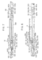
- Each of the slits 7b houses therein a holder 91 (see FIGS. 7 and 8) on which an end of the start gate 9, and a moving mechanism 90 for sliding the holder 91 along the straight stretch of the race courses.
- the moving mechanism 90, the holder 91, and the start gate 9 in each of the slits 7b will be described below.
- the upper opening of the frame 901 has an upper edge lying flush with the upper surface of the edge bank 7.
- FIGS. 7 and 8 only show mechanical structures mounted on the frame 901.
- a motor 902 is fixedly mounted in the frame 901 near one end thereof, i.e., a right-hand end as viewed in FIGS. 7 and 8.
- the motor 902 has a rotatable shaft extending transversely of the frame 901, i.e., vertically in FIG. 7 or in a direction normal to the sheet of FIG. 8.
- the rotatable shaft of the motor 902 is operatively coupled to a train of speed reduction gears in a gear box 903 that is fixed to an inner surface of a first side wall (an upper side wall in FIG. 3 which faces the track 5) 901a of the frame 901.
- a drive pulley 904 which is rotatable by the motor 902 through the train of speed reduction gears is rotatably mounted on an outer surface of the gear box 903 parallel to the motor 902.
- the drive pulley 904 and the driven pulley 905 are rotatable in a common vertical plane and positioned at the same height.
- a drive belt 906 is trained around the drive pulley 904 and the driven pulley 905 and has opposite ends fixed respectively to belt fixtures 911a, 911b attached to respective opposite ends of a movable base 911 while the drive belt 906 is kept under tension.
- the drive belt 906 and the movable base 911 jointly make up an loop for rotating the drive and driven pulleys 904, 905 in unison with each other.
- a slide rail 908 is attached to an inner surface of a second side wall 901b of the frame 901 parallel to the drive belt 906.
- the slide rail 908 is positioned at the same height as the drive and driven pulleys 904, 905.
- a slider 909 disposed parallel to the second side wall 801b has a slidable ridge 909a slidably, but unremovably, mounted on the slide rail 908.
- the slider 909 also has a pair of microswitch trigger members 909b, 909c extending longitudinally of the frame 901 and integral with respective lower corners of the slider 909.
- the slider 909 is securely coupled to the movable base 911. Therefore, when the motor 902 is energized, the rotation of the rotatable shaft thereof is transmitted through the train of speed reduction gears in the gear box 903 to the drive pulley 904. When the drive pulley 904 is rotated, the movable base 911 is moved along the slide rail 908 between the drive and driven pulleys 904, 905 by the drive belt 906 that is trained around the drive and driven pulleys 904, 905.
- a stroke limit detecting microswitch (detecting device) 907 ⁇ is fixed to the bottom of the frame 901 near its one end.
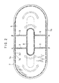
- the stroke limit detecting microswitch 907 ⁇ can be actuated upon contact with the microswitch trigger member 909b when the start gate 9 moves to a position ⁇ shown in FIG. 2.
- a stroke limit detecting microswitch (detecting device) 907 ⁇ is fixed to the bottom of the frame 901 near its opposite end.
- the stroke limit detecting microswitch 907 ⁇ can be actuated upon contact with the microswitch trigger member 909c when the start gate 9 moves to a position ⁇ shown in FIG. 2.
- the control system 3 controls the motor 902 to stop its rotation in one direction and to be reversed only.
- the movable base 911 which is part of the holder 91, is in the form of a planar member which is rectangular in shape as viewed in plan.
- a motor 912 which has a rotatable shaft extending vertically as viewed in FIG. 8 is fixedly mounted on the upper surface of an end of the movable base 911 closer to the driven pulley 905.
- the rotatable shaft of the motor 912 extends through the movable base 911 and is operatively coupled to a train of speed reduction gears in a gear box 913 that is fixed to a lower surface of the movable base 911.
- the train of speed reduction gears has an output shaft extending through the movable base 911 and having a tip end connected to a drive pulley 914 which is rotatably mounted substantially centrally on the movable base 911.
- the drive pulley 914 has a rotatable shaft extending vertically.
- a vertical start gate support shaft 920 is rotatably mounted on the upper surface of an opposite end of the movable base 911 which is closer to the drive pulley 904.
- a driven pulley 915 which is larger in diameter than the drive pulley 914, is attached to the start gate support shaft 920 at the same height as the drive pulley 914.
- An endless drive belt 916 is trained around the drive pulley 914 and the driven pulley 915 for transmitting the rotation of the drive pulley 914, as reduced in speed by the gear box 913, to the start gate support shaft 920.
- the start gate support shaft 920 has on its upper end a large-diameter portion 920a which is slightly large in diameter than the driven pulley 915.
- a joint 917 which is substantially L-shaped in plan, has an end fixed to the tip end of the large-diameter portion 920a.
- the start gate 9 has a proximal end 9a fixed to the other end of the joint 917.
- the start gate 9 comprises an elongate planar bar and has nine spaced frame plates 9b mounted on a lower surface thereof.
- the frame plates 9b define eight start frames for the respective racehorses (movable bodies) H.
- the motor 912 When the motor 912 is energized, the rotation of the rotatable shaft thereof is transmitted through the train of speed reduction gears in the gear box 913 to the drive pulley 914.
- the start gate support shaft 920 When the drive pulley 914 is rotated, the start gate support shaft 920 is angularly moved by the drive belt 916 that is trained around the drive and driven pulleys 914, 915.
- the start gate 9 which is connected in offset relation to the start gate support shaft 920 by the joint 917 is angularly moved about the start gate support shaft 920.
- the large-diameter portion 920a has a tooth 918 mounted on a circumferential surface thereof.
- a retracted position detecting microswitch 919a which is fixedly mounted on an upper surface of the movable base 911 is actuated upon contact with the tooth 918 when the start gate 9 is angularly moved to a retracted position parallel to the slit 7b as shown in FIGS. 7 through 9.
- a set position detecting microswitch 919b which is fixedly mounted on an upper surface of the movable base 911 is actuated upon contact with the tooth 918 when the start gate 9 is angularly moved to a set position perpendicular to the slit 7b as shown in FIG. 10.
- a cable conduit 92 which comprises a number of articulated sheaths so as to be flexible in one direction has an end attached to the upper end of the movable base 911 at an edge closer to the drive pulley 905.
- the cable conduit 92 extends from the movable base 911 toward the drive pulley 905, is turned 180°, then extends on the bottom of the frame 901 toward a center of the frame 901 where the opposite end of the cable conduit 92 is fixed to the bottom of the frame 901.
- the cable conduit 92 houses electric wires by which the control system 3 and the motor 912 are electrically connected. Therefore, no matter where the movable base 911 may be positioned in its stroke, electric energy can be supplied to the motor 912 by electric wires, and the cable conduit 92 is prevented from being stuck or twisted in the frame 901.
- the motors 802, 905, 912 are electrically connected to a motor driver 37 in the control system 3.
- the motor driver 37 selectively energizes the motors 802, 905, 912 to establish race courses.
- the motor driver 37 may energize the motors 802 to move the movable members 82 to establish either short-distance race courses by retracting the movable members 82 into the fixed member 81 to contract the central field 8 as shown in the solid lines in FIG. 2, or long-distance race courses by pulling the movable members 82 out of the fixed member 81 to extend the central field 8 as shown in the broken lines in FIG. 2.
- the motor driver 37 may energize either one of the motors 912 to set an upper start gate (first start gate) 9 as viewed in FIG. 2 or a lower start gate (second start gate) 9 as viewed in FIG. 2 over the track 5, and may also energize the corresponding motor 905 to move the set start gate 9 to a position ⁇ or a position ⁇ +. Therefore, there are available a total of four start gate positions as shown in FIG. 2. Consequently, the motor driver 7 can arrange a total of 8 race course selections.
- the controller 31 in the control system 3, which serves as a central processing unit for controlling overall operation of the horse racing game apparatus 1, can establish either a clockwise direction or a counterclockwise direction in which the race horses (movable bodies) H run along the track 5. As a result, the horse racing game apparatus 1 can provide a total of 16 race course selections for simulated horse races.
- a number of light-emitting elements 341 such as light-emitting diodes are mounted on an outer circumferential surface of the track 5, i.e., the inner wall 7a of the edge bank 7, and an inner circumferential surface of the track 5, i.e., the outer circumferential edge of the central field 8.
- the light-emitting elements 341 are selectively turned on to indicate a goal by a flickering circuit 34 that is controlled by the controller 31.
- the start gate 9 has a total of 8 frames for race horses (movable bodies) H, and 8 race horses (movable bodies) H are placed on the track 5.
- Serial horse numbers are assigned to the respective race horses (movable bodies) H.
- the horse numbers can be established by setting 4-bit DIP switches on self-propelled vehicles 44 (described later on) of the respective race horses (movable bodies) H.
- FIG. 12 schematically shows a mechanism for moving each of the race horses (movable bodies) H.
- a base plate 43 of transparent synthetic resin underlies the track 5 parallel thereto, with each of the self-propelled vehicles 44 being disposed in a space defined between the upper surface of the base plate 43 and the track 5.
- Positive and negatives square-shaped electrodes that are out of phase with each other by 90 ° are disposed adjacent to each other on the lower surface of the track 5.
- each of the self-propelled vehicles 44 has a plurality of electrode pins disposed on an upper surface thereof along one radial line and normally biased to project upwardly. At least one of the electrode pins is held in sliding contact with each of the positive and negatives square-shaped electrodes on the lower surface of the track 5.
- the self-propelled vehicle 44 also has a propulsion motor (not shown) energizable by electric energy supplied from the electrode pins held in sliding contact with the positive and negatives square-shaped electrodes, a pair of transversely spaced drive wheels 44a rotatable by the propulsion motor, and a driven wheel 44b positioned ahead of the drive wheels 44a, i.e., to the right of the drive wheels 44a as viewed in FIG. 12.
- the self-propelled vehicle 44 can make a right turn or a left turn when the drive wheels 44a rotate at different speeds, and can run straight when the drive wheels 44a rotate at the same speed.
- the self-propelled vehicle 44 can change its speed of travel by changing the speed of rotation of the drive wheels 44a.
- the self-propelled vehicle 44 has on its upper surface an X-shaped linkage and a resilient member for normally biasing the X-shaped linkage upwardly. Rollers are mounted on the X-shaped linkage for limiting the vertical spacing between the lower surface of the track 5 and the X-shaped linkage, and a magnet 44c is fixedly mounted on the X-shaped linkage so as to be slightly spaced from the lower surface of the track 5.
- the race horse (movable body) H comprises a chassis H1 and a horse model H2 fixedly mounted on the chassis H1 by a vertical support rod.
- the chassis H1 has wheels on its lower surface.
- a magnet H3 is also mounted on the lower surface of the chassis H1 in vertical alignment with the magnet 44c, and has a magnetic pole which faces an unlike magnetic pole of the magnet 44c.
- the race horse (movable body) H can thus move on the track 5 in order to follow movement of the self-propelled vehicle 44 on the track 5.
- Light-emitting elements 44d are mounted on front and rear edges of the lower surface of the self-propelled vehicle 44.
- the front and rear light-emitting elements 44d can be turned on with a slight time difference to emit light rays which allow the race horse (movable body) H to be identified in position and direction.
- the light-emitting elements 44d of the respective self-propelled vehicles 44 are turned on successively with the sequence and timing depending on the horse numbers established by the DIP switches. By recognizing the sequence and timing, it is possible to recognize the present positions of the respective self-propelled vehicles 44, i.e., the race horses (movable bodies) H on the track 5.
- Light emitted from the light-emitting elements 44d is imaged by a CCD camera 331 which is positioned below the base plate 43 for capturing an image of the entire lower surface of the base plate 43.
- the self-propelled vehicle 44 also has on its lower surface an infrared detector 44e for detecting an infrared radiation signal (control signal) emitted from a plurality of transmission LEDs 321 positioned below the base plate 43.
- a control signal detected by the infrared detector 44e is transmitted to a controller (not shown) in the self-propelled vehicle 44 to control operation of the self-propelled vehicle 44 with respect to the rotational speed of the propulsion motor and the speed difference between the drive wheels 44a for directional control.
- a race carried out by the race horses (movable bodies) H on the track 5 is controlled by the control system 3.
- the control system 3 has a position detector 33 which detects the positions and directions of the respective race horses (movable bodies) H on the track 5 based on a detected signal which is generated by the CCD camera 331 that images the light-emitting elements 44d of the respective self-propelled vehicles 44.
- the detected positions and directions are supplied from the position detector 33 to the controller 31.
- the controller 31 Based on the supplied positions and directions, the controller 31 outputs a control signal to an infrared LED driver 32 according to a game program stored in a built-in ROM (not shown).
- the infrared LED driver 32 outputs the received control signal to the transmission LEDs 321.
- the control signal is associated with addresses representing the horse numbers of the respective race horses (movable bodies) H for individually controlling the race horses (movable bodies) H.
- a simulated horse race performed by the horse racing game apparatus 1 will briefly be described below.
- the motor driver 37 establishes race courses, and the controller 31 determines the direction in which the race horses (movable bodies) H are to move along the track 5, the number of times that the race horses (movable bodies) H are to run around the track 5, and a goal position.
- the controller 31 then outputs a control signal through the transmission LEDs 321 to the race horses (movable bodies) H on the track 5 for thereby instructing the race horses (movable bodies) H to move into the respective frames of the start gate 9 which has been set over the track 5.
- the race horses (movable bodies) H now enter into the frames which correspond to their own horse numbers.
- the race horses (movable bodies) H start moving on the track 5.
- the motor driver 37 reverses the motor 912 to move the start gate 9 from the set position back to the retracted position on the slit 5b.
- Movement of the race horses (movable bodies) H during the race is controlled according to speeds and instantaneous forces calculated by the controller 31 based on predetermined characteristic data (distribution functions as to standard speeds and instantaneous forces, peculiar properties of the race horses) of the race horses (movable bodies) H which have been stored in the controller 31 and also random numbers generated at given time intervals.
- the controller 31 controls them so as to run around the corresponding movable member 82 of the central field 8 at that time.
- the race horses (movable bodies) H thus controlled reach the goal, their results are indicated to the player's consoles 2 to discharge medals through the medal discharge area 22b.
- the horse racing game apparatus 1 allows the central field 8 to be selectively extended and contracted in its longitudinal direction to change the inner circumferential length of the track 5, and also allows the start gate 9 to change its position.
- the horse racing game apparatus 1 is relatively simple in structure and small in size, but is capable of arranging a wide variety of race course selections.
- the horse racing game apparatus 1 can arrange a wide variety of race course selections with a relatively simple structure.
Landscapes
- Engineering & Computer Science (AREA)
- Multimedia (AREA)
- Toys (AREA)
Claims (11)
- Machine de jeu de courses (1) comprenant :caractérisée en ce que ledit indicateur de position de départ (9) est disposé de manière pouvoir être déplacé le long desdits circuits de course.un plateau de jeu (5) avec des circuits de course établis sur celui-ci,une pluralité de corps mobiles (H) qui peuvent être déplacés le long desdits circuits de course pour des classements, etun indicateur de position de départ (9) indiquant une position de départ pour les circuits de course,
- Machine de jeu de courses (1) selon la revendication 1, comprenant en outre :un mécanisme pour déplacer ledit indicateur de position de départ (9) le long desdits circuits de course.
- Machine de jeu de courses (1) selon la revendication 2, comprenant une pluralité desdits indicateurs de position de départ (9) et une pluralité desdits mécanismes.
- Machine de jeu de courses selon une quelconque des revendications 1 à 3, dans laquelle ledit indicateur de position de départ (9) est en forme de barre.
- Machine de jeu de courses selon une quelconque des revendications 1 à 4, comprenant en outre :un support (91) pour porter ledit indicateur de position de départ (9) en forme de barre en vue de son déplacement entre une première position dans laquelle ledit indicateur de position de départ (9) en forme de barre repose sur lesdits circuits de course et en travers de ceux-ci et une deuxième position dans laquelle ledit indicateur de position de départ (9) en forme de barre est retiré desdits circuits de course, etun mécanisme (90) pour mouvoir ledit support (91) le long desdits circuits de course.
- Machine de jeu de courses (1) selon les revendications 4 et 5, comprenant une pluralité desdits indicateurs de position de départ (9) en forme de barre, une pluralité desdits supports (91) et une pluralité desdits mécanismes (90), ladite première position pouvant être occupée seulement par l'un desdits indicateurs de position de départ (9) en forme de barre.
- Machine de jeu de courses (1) selon une quelconque des revendications 1 à 6, comprenant en outre :un champ central (8) monté sur ledit plateau de jeu et définissant un chemin circonférentiel intérieur pour les circuits de course, ledit champ central (8) étant sélectivement extensible et contractile dans au moins une direction, etun mécanisme (80) pour étendre et contracter sélectivement ledit champ central.
- Machine de jeu de courses (1) selon la revendication 5, dans laquelle ledit mécanisme (90) comprend un mécanisme pour déplacer ledit support (91) dans une pluralité de positions prédéterminées.
- Machine de jeu de courses (1) selon la revendication 8, dans laquelle ledit mécanisme comprend :un détecteur pour détecter ledit support dans chacune desdites positions prédéterminées, etun actionneur pour déplacer lesdits membres mobiles (H) jusqu'à ce que ledit détecteur détecte ledit support (91) dans chacune des positions prédéterminées.
- Machine de jeu de courses (1) selon la revendication 9, dans laquelle ledit détecteur comprend un commutateur miniature.
- Machine de jeu de courses (1) selon la revendication 8, dans laquelle ladite pluralité de positions prédéterminées comprend deux positions.
Priority Applications (1)
| Application Number | Priority Date | Filing Date | Title |
|---|---|---|---|
| EP20030013379 EP1350544B1 (fr) | 1996-08-21 | 1997-08-21 | Machine de jeu de courses |
Applications Claiming Priority (6)
| Application Number | Priority Date | Filing Date | Title |
|---|---|---|---|
| JP220222/96 | 1996-08-21 | ||
| JP22022396A JP2792846B2 (ja) | 1996-08-21 | 1996-08-21 | 競走ゲーム装置 |
| JP220223/96 | 1996-08-21 | ||
| JP22022296A JP2792845B2 (ja) | 1996-08-21 | 1996-08-21 | 競走ゲーム装置 |
| JP22022396 | 1996-08-21 | ||
| JP22022296 | 1996-08-21 |
Related Child Applications (1)
| Application Number | Title | Priority Date | Filing Date |
|---|---|---|---|
| EP20030013379 Division EP1350544B1 (fr) | 1996-08-21 | 1997-08-21 | Machine de jeu de courses |
Publications (3)
| Publication Number | Publication Date |
|---|---|
| EP0824946A2 EP0824946A2 (fr) | 1998-02-25 |
| EP0824946A3 EP0824946A3 (fr) | 1999-11-24 |
| EP0824946B1 true EP0824946B1 (fr) | 2003-07-16 |
Family
ID=26523591
Family Applications (2)
| Application Number | Title | Priority Date | Filing Date |
|---|---|---|---|
| EP20030013379 Expired - Lifetime EP1350544B1 (fr) | 1996-08-21 | 1997-08-21 | Machine de jeu de courses |
| EP97114497A Expired - Lifetime EP0824946B1 (fr) | 1996-08-21 | 1997-08-21 | Machine de jeu de courses |
Family Applications Before (1)
| Application Number | Title | Priority Date | Filing Date |
|---|---|---|---|
| EP20030013379 Expired - Lifetime EP1350544B1 (fr) | 1996-08-21 | 1997-08-21 | Machine de jeu de courses |
Country Status (6)
| Country | Link |
|---|---|
| US (1) | US5924927A (fr) |
| EP (2) | EP1350544B1 (fr) |
| CN (1) | CN1152729C (fr) |
| AU (1) | AU710663B2 (fr) |
| DE (2) | DE69731414D1 (fr) |
| TW (1) | TW362987B (fr) |
Families Citing this family (46)
| Publication number | Priority date | Publication date | Assignee | Title |
|---|---|---|---|---|
| JP2001224840A (ja) * | 2000-02-15 | 2001-08-21 | Konami Co Ltd | ゲームシステム |
| GB2367254A (en) * | 2000-08-02 | 2002-04-03 | Coinmaster Gaming Ltd | Simulated race game with touch screen betting |
| US7976389B2 (en) | 2000-09-29 | 2011-07-12 | Igt | Method and apparatus for gaming machines with a tournament play bonus feature |
| JP2002282530A (ja) * | 2001-03-28 | 2002-10-02 | Konami Co Ltd | 自走体によるゲーム装置 |
| US6786824B2 (en) * | 2001-05-25 | 2004-09-07 | Igt | Method, apparatus, and system for providing a player with opportunities to win a feature event award |
| EP1288820A3 (fr) * | 2001-07-19 | 2003-03-12 | Sega Corporation | Procédé pour faire des paris sur des courses |
| JP4957938B2 (ja) | 2001-09-19 | 2012-06-20 | 株式会社セガ | ゲームプログラム、ゲーム装置及びネットワークサーバ |
| US20030060264A1 (en) * | 2001-09-21 | 2003-03-27 | Chilton Ward W. | Gaming device providing tournament entries |
| US7892088B2 (en) * | 2001-10-18 | 2011-02-22 | Steve Brandstetter | Gaming device having a second separate bonusing event |
| US7169041B2 (en) * | 2001-12-04 | 2007-01-30 | Igt | Method and system for weighting odds to specific gaming entities in a shared bonus event |
| US7485043B2 (en) | 2002-06-19 | 2009-02-03 | Igt | Elimination games for gaming machines |
| US7314408B2 (en) | 2003-07-23 | 2008-01-01 | Igt | Methods and apparatus for a competitive bonus game with variable odds |
| US7354342B2 (en) | 2003-07-30 | 2008-04-08 | Igt | Gaming device having a multiple coordinate award distributor including award percentages |
| US7402106B2 (en) * | 2004-03-24 | 2008-07-22 | Bay Tek Games, Inc. | Computer controlled car racing game |
| US7892093B2 (en) | 2004-08-19 | 2011-02-22 | Igt | Gaming system having multiple gaming machines which provide bonus awards |
| CN101043922A (zh) | 2004-08-19 | 2007-09-26 | Igt公司 | 具有多个提供奖金奖励的游戏机的游戏系统 |
| US8251791B2 (en) | 2004-08-19 | 2012-08-28 | Igt | Gaming system having multiple gaming machines which provide bonus awards |
| WO2006028740A2 (fr) | 2004-09-01 | 2006-03-16 | Igt | Systeme de jeux a dispositifs de jeu multiples partageant un affichage multi-sortie |
| US7666088B2 (en) * | 2004-09-28 | 2010-02-23 | Igt | Methods and apparatus for playing a gaming pool for a feature event bonus game |
| USD548288S1 (en) | 2004-09-30 | 2007-08-07 | Igt | Gaming system having a gaming machine display and at least one spacer display |
| USD537886S1 (en) | 2004-09-30 | 2007-03-06 | Igt | Gaming system dome cap for a shared symbol display |
| USD523093S1 (en) | 2004-09-30 | 2006-06-13 | Igt | Gaming system having a shared symbol display |
| US8651939B2 (en) | 2004-10-01 | 2014-02-18 | Igt | Gaming system having a plurality of adjacently arranged gaming machines and a mechanical moveable indicator operable to individually indicate the gaming machines |
| JP3842806B2 (ja) * | 2005-01-17 | 2006-11-08 | 株式会社コナミデジタルエンタテインメント | 情報認識装置及びシート |
| US9640017B2 (en) | 2005-08-31 | 2017-05-02 | Igt | Gaming system and method employing rankings of outcomes from multiple gaming machines to determine awards |
| US20070082730A1 (en) * | 2005-10-08 | 2007-04-12 | Brown Patrick L | Pari-mutuel betting kiosk |
| US8814669B2 (en) | 2005-12-08 | 2014-08-26 | Igt | Systems and methods for post-play gaming benefits |
| WO2007119659A1 (fr) * | 2006-04-05 | 2007-10-25 | Kabushiki Kaisha Sega Doing Business As Sega Corporation | Dispositif de jeu à palets |
| US7689302B2 (en) | 2006-06-13 | 2010-03-30 | Igt | Server based gaming system and method for selectively providing one or more different tournaments |
| US7967677B2 (en) | 2006-11-08 | 2011-06-28 | Igt | Gaming system and method for providing virtual drawings |
| US8105149B2 (en) | 2006-11-10 | 2012-01-31 | Igt | Gaming system and method providing venue wide simultaneous player participation based bonus game |
| US8651947B2 (en) | 2007-11-09 | 2014-02-18 | Igt | Gaming system and method providing a multiple-player bonus redemption game |
| US8118666B2 (en) | 2008-07-15 | 2012-02-21 | Igt | Gaming system, gaming devices, and method for providing an enhanced multiple-player bonus redemption game |
| US8292745B2 (en) * | 2009-02-27 | 2012-10-23 | Digideal Corporation | Convertible rail for selecting player-tracking modes in an electronic game table |
| US8419546B2 (en) | 2009-08-31 | 2013-04-16 | Igt | Gaming system and method for selectively providing an elimination tournament that funds an award through expected values of unplayed tournament games of eliminated players |
| US8475265B2 (en) | 2011-09-28 | 2013-07-02 | Igt | Gaming system, gaming device, and method for providing a multiple player persistent game |
| US8662980B2 (en) | 2011-09-28 | 2014-03-04 | Igt | Gaming system, gaming device, and method for providing a multiple player persistent game |
| US8905831B2 (en) | 2011-09-28 | 2014-12-09 | Igt | Gaming system, gaming device, and method for providing a multiple player persistent game |
| US8795063B2 (en) | 2012-03-27 | 2014-08-05 | Igt | Gaming system, gaming device, and method for providing a multiple player game |
| US8708804B2 (en) | 2012-06-22 | 2014-04-29 | Igt | Gaming system and method providing a collection game including at least one customizable award collector |
| US10055930B2 (en) | 2015-08-11 | 2018-08-21 | Igt | Gaming system and method for placing and redeeming sports bets |
| US10032338B2 (en) | 2015-09-23 | 2018-07-24 | Igt | Gaming system and method providing a gaming tournament having a variable average expected point payout |
| WO2017196514A1 (fr) | 2016-05-13 | 2017-11-16 | Konami Gaming, Inc. | Système de jeu, procédé de commande pour système de jeu et programme pour machine de jeu, destinés à fournir un jeu avec une possibilité de bonus |
| US10424162B2 (en) | 2016-09-23 | 2019-09-24 | Igt | Gaming system and method providing a gaming tournament with a dynamic equalizer feature |
| US10733838B2 (en) | 2018-11-16 | 2020-08-04 | Igt | Gaming system and method providing tournament-style free activation feature |
| US11458408B2 (en) * | 2019-12-10 | 2022-10-04 | Microsoft Technology Licensing, Llc | Race royale gameplay through video game |
Family Cites Families (6)
| Publication number | Priority date | Publication date | Assignee | Title |
|---|---|---|---|---|
| US1703378A (en) * | 1928-05-21 | 1929-02-26 | Howard N Barnum | Amusement device |
| US2751227A (en) * | 1955-03-14 | 1956-06-19 | Benjamin H Seltzman | Racing game |
| US3297323A (en) * | 1963-05-20 | 1967-01-10 | Jr John C Gibson | Racing game |
| DE69212904T2 (de) * | 1991-05-30 | 1997-01-30 | Sega Enterprises Kk | Bildschirmsimulationssystem für Spielvorrichtung |
| US5382021A (en) * | 1993-06-07 | 1995-01-17 | Sigma, Incorporated | Horse racing game having rotating arm and tethered members |
| JP3870493B2 (ja) * | 1996-08-02 | 2007-01-17 | 株式会社セガ | 競争ゲーム装置 |
-
1997
- 1997-08-15 TW TW086111763A patent/TW362987B/zh active
- 1997-08-20 AU AU35190/97A patent/AU710663B2/en not_active Ceased
- 1997-08-20 US US08/914,952 patent/US5924927A/en not_active Expired - Fee Related
- 1997-08-21 DE DE69731414T patent/DE69731414D1/de not_active Expired - Lifetime
- 1997-08-21 EP EP20030013379 patent/EP1350544B1/fr not_active Expired - Lifetime
- 1997-08-21 EP EP97114497A patent/EP0824946B1/fr not_active Expired - Lifetime
- 1997-08-21 CN CNB971185654A patent/CN1152729C/zh not_active Expired - Fee Related
- 1997-08-21 DE DE69723511T patent/DE69723511T2/de not_active Expired - Fee Related
Also Published As
| Publication number | Publication date |
|---|---|
| AU710663B2 (en) | 1999-09-23 |
| EP0824946A2 (fr) | 1998-02-25 |
| EP0824946A3 (fr) | 1999-11-24 |
| AU3519097A (en) | 1998-02-26 |
| HK1059058A1 (en) | 2004-06-18 |
| CN1179346A (zh) | 1998-04-22 |
| EP1350544A1 (fr) | 2003-10-08 |
| CN1152729C (zh) | 2004-06-09 |
| EP1350544B1 (fr) | 2004-10-27 |
| DE69723511D1 (de) | 2003-08-21 |
| DE69723511T2 (de) | 2004-05-13 |
| TW362987B (en) | 1999-07-01 |
| DE69731414D1 (de) | 2004-12-02 |
| US5924927A (en) | 1999-07-20 |
Similar Documents
| Publication | Publication Date | Title |
|---|---|---|
| EP0824946B1 (fr) | Machine de jeu de courses | |
| EP0864341B1 (fr) | Appareil pour jeux de competition | |
| JP2659176B2 (ja) | 競争ゲーム装置 | |
| JP2668343B2 (ja) | 競争ゲーム装置 | |
| US20010006915A1 (en) | Table tennis apparatus | |
| US6059657A (en) | Game machine | |
| EP0757917B1 (fr) | Appareil de simulation de jeu de compétition avec un dispositif de guidage de cours | |
| EP0728505B1 (fr) | Système d'alimentation électrique d'un objet mobile | |
| US20100035684A1 (en) | System and method for controlling movement of a plurality of game objects along a playfield | |
| JP3019137B2 (ja) | 走行模型体 | |
| US5688175A (en) | Game machine | |
| HK1059058B (en) | Racing game apparatus | |
| JP2792846B2 (ja) | 競走ゲーム装置 | |
| DE69708709T2 (de) | Spielmaschine | |
| JP3497474B2 (ja) | 競争ゲーム装置 | |
| JPH1057619A (ja) | 競走ゲーム装置 | |
| JP3593068B2 (ja) | ゲーム装置用位置検出装置 | |
| US20090322021A1 (en) | Hockey Exhibit with Hockey Simulation and Promotional Methods Used in Connection Therewith |
Legal Events
| Date | Code | Title | Description |
|---|---|---|---|
| PUAI | Public reference made under article 153(3) epc to a published international application that has entered the european phase |
Free format text: ORIGINAL CODE: 0009012 |
|
| AK | Designated contracting states |
Kind code of ref document: A2 Designated state(s): DE GB |
|
| PUAL | Search report despatched |
Free format text: ORIGINAL CODE: 0009013 |
|
| PUAF | Information related to the publication of a search report (a3 document) modified or deleted |
Free format text: ORIGINAL CODE: 0009199SEPU |
|
| PUAL | Search report despatched |
Free format text: ORIGINAL CODE: 0009013 |
|
| AK | Designated contracting states |
Kind code of ref document: A3 Designated state(s): AT BE CH DE DK ES FI FR GB GR IE IT LI LU MC NL PT SE |
|
| D17D | Deferred search report published (deleted) | ||
| 17P | Request for examination filed |
Effective date: 20000525 |
|
| AKX | Designation fees paid |
Free format text: DE GB |
|
| 17Q | First examination report despatched |
Effective date: 20020614 |
|
| GRAH | Despatch of communication of intention to grant a patent |
Free format text: ORIGINAL CODE: EPIDOS IGRA |
|
| RAP1 | Party data changed (applicant data changed or rights of an application transferred) |
Owner name: KONAMI CORPORATION |
|
| GRAH | Despatch of communication of intention to grant a patent |
Free format text: ORIGINAL CODE: EPIDOS IGRA |
|
| GRAA | (expected) grant |
Free format text: ORIGINAL CODE: 0009210 |
|
| AK | Designated contracting states |
Designated state(s): DE GB |
|
| REG | Reference to a national code |
Ref country code: GB Ref legal event code: FG4D |
|
| REF | Corresponds to: |
Ref document number: 69723511 Country of ref document: DE Date of ref document: 20030821 Kind code of ref document: P |
|
| PGFP | Annual fee paid to national office [announced via postgrant information from national office to epo] |
Ref country code: DE Payment date: 20031028 Year of fee payment: 7 |
|
| PLBE | No opposition filed within time limit |
Free format text: ORIGINAL CODE: 0009261 |
|
| STAA | Information on the status of an ep patent application or granted ep patent |
Free format text: STATUS: NO OPPOSITION FILED WITHIN TIME LIMIT |
|
| 26N | No opposition filed |
Effective date: 20040419 |
|
| PG25 | Lapsed in a contracting state [announced via postgrant information from national office to epo] |
Ref country code: DE Free format text: LAPSE BECAUSE OF NON-PAYMENT OF DUE FEES Effective date: 20050301 |
|
| REG | Reference to a national code |
Ref country code: GB Ref legal event code: 732E Free format text: REGISTERED BETWEEN 20090514 AND 20090520 |
|
| PGFP | Annual fee paid to national office [announced via postgrant information from national office to epo] |
Ref country code: GB Payment date: 20140820 Year of fee payment: 18 |
|
| GBPC | Gb: european patent ceased through non-payment of renewal fee |
Effective date: 20150821 |
|
| PG25 | Lapsed in a contracting state [announced via postgrant information from national office to epo] |
Ref country code: GB Free format text: LAPSE BECAUSE OF NON-PAYMENT OF DUE FEES Effective date: 20150821 |