EP0824977A1 - Greifer für System zur Herstellung von Blechartikeln - Google Patents
Greifer für System zur Herstellung von Blechartikeln Download PDFInfo
- Publication number
- EP0824977A1 EP0824977A1 EP97118611A EP97118611A EP0824977A1 EP 0824977 A1 EP0824977 A1 EP 0824977A1 EP 97118611 A EP97118611 A EP 97118611A EP 97118611 A EP97118611 A EP 97118611A EP 0824977 A1 EP0824977 A1 EP 0824977A1
- Authority
- EP
- European Patent Office
- Prior art keywords
- piece
- manipulator
- gripper
- suspension
- suspension head
- Prior art date
- Legal status (The legal status is an assumption and is not a legal conclusion. Google has not performed a legal analysis and makes no representation as to the accuracy of the status listed.)
- Granted
Links
- 239000002184 metal Substances 0.000 title claims abstract description 35
- 239000000725 suspension Substances 0.000 claims abstract description 47
- 238000005452 bending Methods 0.000 claims abstract description 32
- 239000012530 fluid Substances 0.000 claims abstract description 16
- 230000007246 mechanism Effects 0.000 claims description 5
- 238000005259 measurement Methods 0.000 description 7
- 230000006835 compression Effects 0.000 description 3
- 238000007906 compression Methods 0.000 description 3
- 238000011161 development Methods 0.000 description 2
- 238000005352 clarification Methods 0.000 description 1
- 238000012937 correction Methods 0.000 description 1
- 238000004519 manufacturing process Methods 0.000 description 1
- 239000000463 material Substances 0.000 description 1
- 238000000034 method Methods 0.000 description 1
- 238000012986 modification Methods 0.000 description 1
- 230000004048 modification Effects 0.000 description 1
- 230000000452 restraining effect Effects 0.000 description 1
- 238000012546 transfer Methods 0.000 description 1
- 238000013519 translation Methods 0.000 description 1
Images


Classifications
-
- B—PERFORMING OPERATIONS; TRANSPORTING
- B21—MECHANICAL METAL-WORKING WITHOUT ESSENTIALLY REMOVING MATERIAL; PUNCHING METAL
- B21D—WORKING OR PROCESSING OF SHEET METAL OR METAL TUBES, RODS OR PROFILES WITHOUT ESSENTIALLY REMOVING MATERIAL; PUNCHING METAL
- B21D43/00—Feeding, positioning or storing devices combined with, or arranged in, or specially adapted for use in connection with, apparatus for working or processing sheet metal, metal tubes or metal profiles; Associations therewith of cutting devices
- B21D43/02—Advancing work in relation to the stroke of the die or tool
- B21D43/04—Advancing work in relation to the stroke of the die or tool by means in mechanical engagement with the work
- B21D43/10—Advancing work in relation to the stroke of the die or tool by means in mechanical engagement with the work by grippers
- B21D43/105—Manipulators, i.e. mechanical arms carrying a gripper element having several degrees of freedom
-
- B—PERFORMING OPERATIONS; TRANSPORTING
- B21—MECHANICAL METAL-WORKING WITHOUT ESSENTIALLY REMOVING MATERIAL; PUNCHING METAL
- B21D—WORKING OR PROCESSING OF SHEET METAL OR METAL TUBES, RODS OR PROFILES WITHOUT ESSENTIALLY REMOVING MATERIAL; PUNCHING METAL
- B21D11/00—Bending not restricted to forms of material mentioned in only one of groups B21D5/00, B21D7/00, B21D9/00; Bending not provided for in groups B21D5/00 - B21D9/00; Twisting
- B21D11/20—Bending sheet metal, not otherwise provided for
-
- B—PERFORMING OPERATIONS; TRANSPORTING
- B21—MECHANICAL METAL-WORKING WITHOUT ESSENTIALLY REMOVING MATERIAL; PUNCHING METAL
- B21D—WORKING OR PROCESSING OF SHEET METAL OR METAL TUBES, RODS OR PROFILES WITHOUT ESSENTIALLY REMOVING MATERIAL; PUNCHING METAL
- B21D37/00—Tools as parts of machines covered by this subclass
- B21D37/04—Movable or exchangeable mountings for tools
-
- B—PERFORMING OPERATIONS; TRANSPORTING
- B21—MECHANICAL METAL-WORKING WITHOUT ESSENTIALLY REMOVING MATERIAL; PUNCHING METAL
- B21D—WORKING OR PROCESSING OF SHEET METAL OR METAL TUBES, RODS OR PROFILES WITHOUT ESSENTIALLY REMOVING MATERIAL; PUNCHING METAL
- B21D37/00—Tools as parts of machines covered by this subclass
- B21D37/14—Particular arrangements for handling and holding in place complete dies
- B21D37/145—Die storage magazines
-
- B—PERFORMING OPERATIONS; TRANSPORTING
- B21—MECHANICAL METAL-WORKING WITHOUT ESSENTIALLY REMOVING MATERIAL; PUNCHING METAL
- B21D—WORKING OR PROCESSING OF SHEET METAL OR METAL TUBES, RODS OR PROFILES WITHOUT ESSENTIALLY REMOVING MATERIAL; PUNCHING METAL
- B21D5/00—Bending sheet metal along straight lines, e.g. to form simple curves
- B21D5/02—Bending sheet metal along straight lines, e.g. to form simple curves on press brakes without making use of clamping means
- B21D5/0209—Tools therefor
- B21D5/0254—Tool exchanging
-
- Y—GENERAL TAGGING OF NEW TECHNOLOGICAL DEVELOPMENTS; GENERAL TAGGING OF CROSS-SECTIONAL TECHNOLOGIES SPANNING OVER SEVERAL SECTIONS OF THE IPC; TECHNICAL SUBJECTS COVERED BY FORMER USPC CROSS-REFERENCE ART COLLECTIONS [XRACs] AND DIGESTS
- Y10—TECHNICAL SUBJECTS COVERED BY FORMER USPC
- Y10T—TECHNICAL SUBJECTS COVERED BY FORMER US CLASSIFICATION
- Y10T483/00—Tool changing
- Y10T483/16—Tool changing with means to transfer work
Definitions
- the present invention relates to the production of bent sheet-metal articles and concerns a manipulator for an automatic bending system.
- the invention has been developed to solve the problem of the bending of sheet-metal articles of complex shapes which are frequently used in machines such as photocopiers, facsimile machines and various electronic devices. These products are subject to rapid development and manufacturer therefore often changes models from one year to another. Each new model is the product of a redesign, even as regards the various sheet-metal articles which it contains.
- bent sheet-metal articles are therefore produced on a relatively small scale and thus do not justify complex and expensive tools and dies.
- a system for producing bent sheet-metal articles known from U.S. Patent No. 4,991,422 departs radically from previously existing bending systems which use bending presses with fixed frameworks and linear, V-sectioned punches and dies which are movable vertically towards and away from each other.
- the system described in the U.S. Patent mentioned above provides for a piece which is to be bent to be supported by a manipulator so that a region of the piece which is to be bent lies in a vertical suspension plane.
- the bends are effected by means of an oscillating bending machine having two tools which can be disposed in any configuration relative to the piece to be bent.
- the piece is supported by the manipulator in a manner such that it can perform movements of limited extent with five degrees of freedom, excluding rotation about an axis perpendicular to the plane of the undeformed piece of sheet metal.
- the bending machine also has a device for the rapid replacement of the tools, using two rotary turrets carried at the ends of a C-shaped tool-holder structure.
- the object of the present invention is further to develop the bending system, the essential elements of which are described in the aforementioned U.S. Patent No. 4,991,422, and in particular to improve the manipulator which has a critical role in the practical application of this innovative bending system.
- a system for producing bent sheet-metal articles from blanked or laser-cut pieces of sheet metal of shapes corresponding to the development in a plane of the articles to be produced is generally indicated 50.
- the system 50 comprises a station 52 for positioning the pieces of sheet metal, a measurement and storage station 54, a bending station 56, an output station 58 and a device 60 for the automatic replacement of the tools, with a respective tool store 62.
- the bending station 56 comprises a cartesian manipulator 64 including a vertically-movable device 66 carried by a carriage 68 movable along a beam 70 which in turn is movable along guides 72 of a portal structure 74.
- the movable device 66 of the manipulator 64 carries a suspension head 76 which will be described in detail below, for holding vertically, by means of a gripper, a piece of sheet-metal to be bent.
- An important characteristic of the system according to the present invention is constituted by the fact that the gripper is not connected to the suspension head of the manipulator 64, but is connected to the piece to be bent.
- the suspension head 76 of the manipulator 64 has the characteristic that it supports the piece in a manner such that it floats freely, so that the piece is free to perform movements of a limited extent during bending.
- the manipulator 64 which is controlled by a conventional control unit 78, positions the piece in a position which is determined on the basis of a program established in dependence on the geometrical shape of the piece to be worked.
- the bending station 56 also comprises a bending machine 80 comprising a tool-holder structure 82 having a punch 84 and a die 86 which cooperate with each other.
- the tool-holder structure 82 is rotatable about an axis which passes through the bending line defined by the vertex of the V-shaped punch 84 and can also pivot about a horizontal axis perpendicular to the aforesaid axis of rotation. It will therefore be appreciated that the punch 84 and the die 86 can be disposed in any position relative to the piece to be bent.
- the rotary and pivoting movements of the tool-holder structure 82 are brought about by the control unit 78 on the basis of a predetermined program.
- the necessary precision in the positioning of the piece is achieved by virtue of a preliminary determination of the relative piece-manipulator position and of the precise control of the relative manipulator-bending machine positions, which is achieved by virtue of the operating precision of the manipulator 64 and of the bending machine 80.
- the operating principle upon which the bending system according to the invention is based thus consists of the positioning of a piece of sheet metal in a predetermined region in space with great precision and repeatability, and of the modification of the positions of the bending tools relative to the piece, with a corresponding degree of precision and repeatability, by a movement of the bending machine, so as to execute the bend in the desired region.
- the main characteristic of the system according to the present invention is its ability to work on extremely small batches (even a single piece) of pieces with different geometrical shapes, solely by means of the selection of a different working program, without carrying out tooling operations.
- a first problem which had to be solved in order to achieve a high degree of flexibility of the system was that of devising a unit for loading the pieces which enabled shaped pieces of sheet metal of complex shapes and extremely variable dimensions to be stored and subsequently gripped by the suspension head 76 of the manipulator 64.
- each piece is associated with its own gripper which is fitted on to a predetermined region of the undeformed piece of sheet metal.
- the gripper is fitted on to the piece of sheet metal in the positioning station 52 in the manner which will be described in detail below.
- the pieces, with their respective grippers, are disposed in a store 90 to await transfer to the bending station 56.
- the store 90 can easily house pieces of different geometrical shapes without the need for any tooling, by virtue of the use of the gripper.
- the store 90 can accommodate a certain number of grippers which are inserted in a corresponding number of forks forming part of the store.
- the pieces of sheet metal, each gripped by its own gripper, are disposed vertically, suspended by the gripper itself, and thus have no direct connection with the store 90 which is completely independent of the shapes of the sheets.
- the piece After each piece of sheet metal has been provided with its gripper, the piece is subjected to a measurement step carried out by means of a conventional feeler 88.
- the data detected by this measurement are processed and stored by the control unit 78 which establishes the link which exists between a locating system fixed relative to the piece and a locating system which is fixed relative to the gripper and, consequently, is fixed relative to the suspension head 76 of the manipulator 64. Small corrections can thus be made to the program controlling the manipulator 64 to compensate for errors in the positioning of the piece relative to the gripper.
- the piece may be measured when it is already connected to the suspension head 76 of the manipulator 64.
- the feeler 88 must be movable in order to enter and leave the working area. If the cycle for the working of the piece provides for the gripping region to be changed after some bends have been effected, a new measurement can be made after the piece has been gripped in the new position.
- the measurement may be effected outside the working area, without affecting the time taken by the bending cycle, whilst the piece is supported by an auxiliary manipulator 89.
- the manipulator 64 Upon completion of the bending operations, the manipulator 64 brings the worked article to an output station 58, shown schematically by means of a belt conveyor. There may be a device 92 in the output station 58 for removing the grippers from the sheet-metal articles.
- each piece to be bent is fitted with its own gripper.
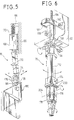
- the gripper 98 is a purely passive element, that is, it does not have opening and closure mechanisms of its own.
- the gripper 98 is constituted by a monolithic metal body having two resilient arms 100, to the ends of which two plates of frictional material 102, between which a piece of sheet metal can be gripped, are fixed.
- a cavity 104 ( Figure 2) is defined between the two arms 100 for housing a mechanism for moving the arms 100 apart resiliently.
- the gripper 98 has a shank 106 with a tapered outer surface for engagement on the suspension head of the manipulator.
- the shank 106 has a through-hole 108 which communicates with the cavity 104 and has a seat 110 for engagement by means which connect the gripper 98 to the manipulator head.
- the gripper 98 also has a pin 112 for the angular location of the gripper relative to the manipulator head and a groove 114 for engagement by a retaining device when the gripper is fitted on a piece of sheet metal.
- gripper just described is advantageous because of its structural simplicity, grippers of other types, even with mechanical closure, could be used.
- An alternative type of gripper could be constituted by one fixed arm and one movable arm which could be tightened against the fixed arm by means of a screw operated by an external device independent of the gripper.
- the gripper 98 has to be fitted on to the piece of sheet metal to be bent in a predetermined position. This is achieved by virtue of a positioning table which is described in detail in EP-A- 0 725 692.
- the pieces of sheet metal After the pieces of sheet metal have been provided with their own grippers, and after they have been subjected to a measurement step, they are moved by a manipulator which positions them precisely in a working region.
- the suspension head 76 of the manipulator that is, the portion of the manipulator which collects the gripper 98 (which is fixed rigidly to the piece), with the movable device 66 of the manipulator, is a critical component of the operating system which has to perform two conflicting tasks.
- the suspension has to ensure a rigid connection between the gripper for gripping the piece and the movable device of the manipulator so that the piece can be positioned precisely in the working space
- the suspension head must leave the piece free to perform slight movements and rotations induced during bending so as not to strain the gripper 98 and the movable device 66 of the manipulator.
- FIG 12 shows schematically the kinematic behaviour of the suspension head 76.
- the movable device 66 of the manipulator carries a suspension body 168 by means of resilient weight-compensation means indicated 170.
- a first pivoting element 172 is articulated to the suspension body 168 and carries, at its lower end, a slide 174 which is movable along the axis X.
- a second pivoting element 176 is articulated to the slide 174 and carries a rotary body 178 having means for engaging the gripper 98 which is fixed to a piece of sheet metal 180 to be bent.
- the arrangement described allows the piece of sheet metal 180 five degrees of freedom constituted by three translatory movements along the axes X, Y and Z, a rotary movement about the axis Z and a pivoting movement about the axis X.
- the piece of sheet metal 180 remains restrained, however, with respect to the last degree of freedom constituted by rotation about the axis Y, which has to be prevented to avoid errors in the positioning of the bending line in the plane of the piece (the plane X-Z).
- the translation along the axis Y is composed of two pivoting movements of the pivoting elements 172 and 176.
- the suspension head 76 can be restrained with respect to all the degrees of freedom by means of the clamping and biasing devices for returning the various elements 168-178 constituting the suspension head to a predetermined attitude.
- Figures 13, 14 and 15 show schematically a practical embodiment of the suspension head, the kinematic layout of which corresponds to Figure 12.
- the suspension body 168 is guided vertically relative to the movable device 66 by means of a four-bar linkage mechanism comprising a pair of upper connecting rods 182 and a lower connecting rod 184 which are articulated to the suspension body 168 and to the movable device 66 on parallel axes.
- the resilient balancing means comprise a first spring 186 interposed under compression between the suspension body 168 and the movable device 66, and having a fixed preloading determined so as to balance the weight of the suspension head 76.
- a second spring 188 is disposed under compression in parallel with the first spring 186 and has a preloading which is variable according to the weight of the piece of sheet-metal 180 connected to the suspension head 76.
- the second spring 188 is interposed between an upper plate 190 fixed to the suspension body 168 and a head 192 carried by a rod 194 movable along the axis Z and operated by a motor 196 controlled by the control unit of the system, to which data relating to the weight of the pieces to be worked have been supplied beforehand.
- the first pivoting element 172 is articulated at its upper end on a pin 198 which also acts as an articulation pin for the lower connecting rod 184 of the four-bar linkage mechanism which guides the vertical movement of the suspension body 168.
- the pivoting element 172 carries a linear guide 200 formed by a roller sliding block extending parallel to the axis of the pin 198 (that is, along the direction (X)).
- the guide 200 is engaged by the slide 174, which carries a pivot pin 204 which is parallel to the axis of the pin 198 and on which the second pivoting element 176 is articulated.
- the second pivoting element 176 supports the rotary body 178 by means of bearings 206 with vertical axes.
- a first clamping device can simultaneously achieve restraint with respect to two degrees of freedom, that is, rotation about the axis X and rotation about the axis Z.
- the clamping device 208 is housed in the body of the slide 174 and cooperates with the second pivoting element 176 and with the rotary body 178.
- a second clamping device 210 is interposed between the first pivoting element 172 and the slide 174 for achieving restraint with respect to the degree of freedom corresponding to movement along the axis X.
- a third clamping device 212 is interposed between the first pivoting element 172 and the suspension body 168 for restraining the element 172 from pivoting about the pin 198.
- a fourth clamping device (not visible in Figure 16) is interposed between the suspension body 168 and the movable device 66.
- the various clamping devices have essentially identical structures and are based on the principle of the gripping between two movable discs a part fixed to a relatively fixed element and a part fixed to a relatively movable element.
- the clamping device comprises first and second pistons 214 and 216 which are connected to each other by means of a shaft 218 and are mounted for sliding in an airtight manner in a chamber 220 in the first pivoting element 172.
- a third piston 222 is slidable in a fluid-tight manner both relative to the chamber 220 and relative to the shaft 218.
- the second and third pistons 216 and 222 act by means of spherical surfaces 224 on respective thrust discs 226 and 228 which are kept separated by a pair of springs 230 and 232.
- a portion 238 which forms part of the first pivoting element 172 and in which two calibrated locating pins 240, disposed at 120°, are slidable to keep the opposed faces of the thrust discs 226, 228 a predetermined distance apart.
- the slide 174 carries rigidly an appendix 242 having a calibrated head 244 which is interposed between the thrust discs 226, 228.
- the thrust discs 226, 228 are kept in the retracted positions by virtue of the springs 230, 232 and do not exert any restraint on the head 244, and the slide 174 is therefore free to move on the guide 200 along the axis X.
- pressurized fluid is supplied to the two supply regions 234, 236 at the same pressure.
- F the force produced by the pressure acting on each piston
- a force equal to 2F will act on the first thrust disc 226, urging it in the direction of the arrow 246, since the forces acting on the first piston 214 and on the second piston 216 are discharged on the first thrust disc 226 by means of the surface 224.
- a force of magnitude F will act on the second thrust disc 228, urging it in the direction indicated by the arrow 248, due to the action of the piston 222 alone.
- the first thrust disc 226 thus adopts a stable locating position against the locating surface 238, whilst the second thrust disc 228 presses the calibrated pins 240 and the calibrated head 244 against the first thrust disc 226.
- the slide 174 is thus brought to a predetermined position which is defined with great repeatability relative to the first pivoting element 172 and remains clamped in that position as long as fluid continues to be supplied to the regions 234, 236.
- the structure and operation of the rest of the clamping devices are identical to those described with reference to the second clamping device 210 with the sole difference that, in the first clamping device 208, two calibrated heads and a single calibrated pin 240 are disposed between the thrust discs 226 and 228, the heads being disposed in angularly offset positions, one head being fixed to the pivoting element 176 and the other to the rotary body 178, so that the operation of the first clamping device simultaneously clamps the second pivoting element 176 and the rotary body 178 and positions them in a predetermined attitude.
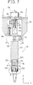
- This device is generally indicated 250 and comprises a piston 252 which is slidable in a fluid tight manner in a chamber 254 in an element 256 which forms part of the rotary body 178.
- the rotary element 178 has a conical seat 258 for housing the shank 106 of the gripper 98.
- This piston 252 carries six gripping fingers 260 of which only two are visible, which can be moved apart resiliently, and are coaxial with the conical seat 258.
- Each finger 160 is formed at its lower end with a protrusion 260a having a tapered surface 260b.
- the engagement fingers 260 are intended to engage the seat 110 of the gripper 98 in their spread-out configuration (shown in Figure 18).
- a helical compression spring 264 is interposed between the rotary body 178 and the piston 252.
- Two chambers, formed on opposite sides of the piston 252 for supply with pressurised fluid are indicated 266 and 268 respectively.
- the clamping configuration of the connecting device 250 is shown in Figure 18.
- the pressurised fluid is sent into the chamber 268 and the force of the fluid is added to the thrust of the spring 264.
- the engagement fingers 260 are moved apart due to their reaction against the shaft 262 and the protrusions 260a engage the seat 110, connecting the gripper 98 firmly to the rotary body 178. It should be noted that the engagement fingers 260 also exert an upward force on the gripper 98, ensuring firm engagement between the conical surfaces of the shank 106 and of the seat 258.
- Figure 18 also shows the engagement between the angular locating pin 112 of the gripper 98 and a seat 270 of the rotary body 178.
- An annular spring 271 is interposed between the seat 270 and the pin 112 to take up play.
Landscapes
- Engineering & Computer Science (AREA)
- Mechanical Engineering (AREA)
- Bending Of Plates, Rods, And Pipes (AREA)
- Mounting, Exchange, And Manufacturing Of Dies (AREA)
- Details Of Indoor Wiring (AREA)
- Making Paper Articles (AREA)
- Laminated Bodies (AREA)
- Diaphragms For Electromechanical Transducers (AREA)
- Details Of Garments (AREA)
- Feeding Of Articles By Means Other Than Belts Or Rollers (AREA)
- Advancing Webs (AREA)
Applications Claiming Priority (3)
| Application Number | Priority Date | Filing Date | Title |
|---|---|---|---|
| ITTO930818 | 1993-10-29 | ||
| ITTO930818A IT1261104B (it) | 1993-10-29 | 1993-10-29 | Sistema per la produzione di pezzi di lamiera piegata e componenti di tale sistema |
| EP94931177A EP0725692B1 (de) | 1993-10-29 | 1994-10-27 | Vorrichtung zum herstellen blechartikeln |
Related Parent Applications (2)
| Application Number | Title | Priority Date | Filing Date |
|---|---|---|---|
| EP94931177A Division EP0725692B1 (de) | 1993-10-29 | 1994-10-27 | Vorrichtung zum herstellen blechartikeln |
| EP94931177.3 Division | 1995-05-04 |
Publications (2)
| Publication Number | Publication Date |
|---|---|
| EP0824977A1 true EP0824977A1 (de) | 1998-02-25 |
| EP0824977B1 EP0824977B1 (de) | 2003-07-02 |
Family
ID=11411843
Family Applications (5)
| Application Number | Title | Priority Date | Filing Date |
|---|---|---|---|
| EP97118611A Expired - Lifetime EP0824977B1 (de) | 1993-10-29 | 1994-10-27 | Greifer für System zur Herstellung von Blechartikeln |
| EP98119348A Expired - Lifetime EP0890396B1 (de) | 1993-10-29 | 1994-10-27 | Vorrichtung zum automatisch Wechseln von Werkzeugen in einer Biegevorrichtung |
| EP98119346A Expired - Lifetime EP0897766B1 (de) | 1993-10-29 | 1994-10-27 | Tisch zur Bestimmung der Position eines Werkstückes aus Metallblech in einem System zur Herstellung von abgekanteten Blechartikeln |
| EP98119347A Expired - Lifetime EP0893170B1 (de) | 1993-10-29 | 1994-10-27 | Biegevorrichtung zur Herstellung von Blechartikeln |
| EP94931177A Expired - Lifetime EP0725692B1 (de) | 1993-10-29 | 1994-10-27 | Vorrichtung zum herstellen blechartikeln |
Family Applications After (4)
| Application Number | Title | Priority Date | Filing Date |
|---|---|---|---|
| EP98119348A Expired - Lifetime EP0890396B1 (de) | 1993-10-29 | 1994-10-27 | Vorrichtung zum automatisch Wechseln von Werkzeugen in einer Biegevorrichtung |
| EP98119346A Expired - Lifetime EP0897766B1 (de) | 1993-10-29 | 1994-10-27 | Tisch zur Bestimmung der Position eines Werkstückes aus Metallblech in einem System zur Herstellung von abgekanteten Blechartikeln |
| EP98119347A Expired - Lifetime EP0893170B1 (de) | 1993-10-29 | 1994-10-27 | Biegevorrichtung zur Herstellung von Blechartikeln |
| EP94931177A Expired - Lifetime EP0725692B1 (de) | 1993-10-29 | 1994-10-27 | Vorrichtung zum herstellen blechartikeln |
Country Status (7)
| Country | Link |
|---|---|
| US (2) | US5857377A (de) |
| EP (5) | EP0824977B1 (de) |
| JP (1) | JP3390447B2 (de) |
| AT (5) | ATE214312T1 (de) |
| DE (5) | DE69431930T2 (de) |
| IT (1) | IT1261104B (de) |
| WO (1) | WO1995011767A1 (de) |
Cited By (2)
| Publication number | Priority date | Publication date | Assignee | Title |
|---|---|---|---|---|
| WO2000014475A1 (en) * | 1998-09-08 | 2000-03-16 | Marposs Societa' Per Azioni | Arm for a head for the linear dimension checking of mechanical pieces and head including said arm |
| WO2000061315A1 (en) * | 1999-04-07 | 2000-10-19 | Amada Company, Limited | Automatic bending system and manipulator for the system |
Families Citing this family (20)
| Publication number | Priority date | Publication date | Assignee | Title |
|---|---|---|---|---|
| DE19621658C2 (de) * | 1996-05-30 | 1999-11-04 | Eht Werkzeugmaschinen Gmbh | Bearbeitungsmaschine für plattenförmige Werkstücke, insbesondere zur Erzeugung von gebogenen Rändern an Blechteilen |
| IT1292330B1 (it) * | 1997-05-27 | 1999-01-29 | Crea Srl | Procedimento per la produzione di pezzi di lamiera piegati |
| US6269677B1 (en) | 1999-12-28 | 2001-08-07 | Abb T&D Technology Ltd. | Press brake back gauge finger |
| US6466843B1 (en) * | 2001-10-16 | 2002-10-15 | General Electric Company | Method and apparatus for lifting objects |
| JP4609810B2 (ja) * | 2004-07-20 | 2011-01-12 | 株式会社アマダ | 曲げ金型及び金型ホルダ並びに金型落下防止装置 |
| DE102004048036A1 (de) * | 2004-09-28 | 2006-04-06 | Ras Reinhardt Maschinenbau Gmbh | Biegeeinrichtung |
| DE102005060763A1 (de) * | 2005-12-16 | 2007-06-21 | Klingel, Hans, Dr. Ing. e.h. | Biegemaschine |
| AT508923B1 (de) * | 2009-11-10 | 2011-05-15 | Trumpf Maschinen Austria Gmbh | Fertigungsanlage, insbesondere für das freiformbiegen |
| US9149852B2 (en) | 2013-03-14 | 2015-10-06 | M.I.C. Industries, Inc. | Panel crimping machine with control system for controlling timing between crimping rollers with an adjustable separation |
| CN104525772A (zh) * | 2014-12-26 | 2015-04-22 | 苏州金逸康自动化设备有限公司 | 一种自动上下料冲压设备 |
| ITUA20163893A1 (it) * | 2016-05-27 | 2017-11-27 | Fabrizio Paoletti | Pressa piegatrice con dispositivo di cambio degli utensili e relativo metodo di cambio |
| CN106270041B (zh) * | 2016-08-08 | 2018-08-14 | 肇庆市端州区明顺电热电器有限公司 | 一种旋转折弯设备及其加工方法 |
| CN113015584A (zh) * | 2018-08-28 | 2021-06-22 | 安大略模具国际公司 | 用于将金属条成形为模具的系统、装置和方法 |
| WO2020056438A2 (de) * | 2018-09-20 | 2020-03-26 | Trumpf Maschinen Austria Gmbh & Co. Kg. | Vakuumgreifer, zuführeinheit sowie verfahren zum transport von flächigen bauteilen |
| IT201800009564A1 (it) * | 2018-10-18 | 2020-04-18 | Starmatik Srl Uninominale | Sistema compatto e preassemblato di lavorazione automatico |
| CN109909371B (zh) * | 2019-04-24 | 2020-11-24 | 白尊敏 | 自动冲孔弯管一体机 |
| CN111589918B (zh) * | 2020-05-25 | 2021-04-13 | 深圳市维鼎精密五金有限公司 | 一种波形散热片的冲压设备 |
| CN113231562B (zh) * | 2021-04-21 | 2022-11-01 | 安徽艾普塑料科技有限公司 | 一种一体式洗衣机滚筒生产装置 |
| JP7236066B2 (ja) * | 2021-06-29 | 2023-03-09 | 株式会社オーエイプロト | パネル成形体のスプリングバック修正装置 |
| CN114345721B (zh) * | 2021-11-29 | 2023-05-09 | 上海工程技术大学 | 一种v形零件引脚扩缩整形装置 |
Citations (1)
| Publication number | Priority date | Publication date | Assignee | Title |
|---|---|---|---|---|
| US4991422A (en) * | 1988-05-16 | 1991-02-12 | Amada Company, Limited | Plate bending machine |
Family Cites Families (16)
| Publication number | Priority date | Publication date | Assignee | Title |
|---|---|---|---|---|
| US4775135A (en) * | 1982-03-12 | 1988-10-04 | Trumpf Gmbh & Co. | Apparatus and method for clamping and positioning workpiece in machine tools |
| US4519284A (en) * | 1982-07-26 | 1985-05-28 | The Warner & Swasey Company | Universal sheet metal holder |
| DE3245755A1 (de) * | 1982-12-10 | 1984-06-14 | Dorstener Maschinenfabrik Ag, 4270 Dorsten | Verfahren zum korrigieren der biegelinie des biegewerkzeuges einer biegepresse, insbesondere abkantpresse |
| EP0115602A1 (de) * | 1983-01-06 | 1984-08-15 | Hämmerle AG | Vorrichtung zum Manipulieren von Werkstücken |
| US4658625A (en) * | 1984-03-30 | 1987-04-21 | Amada Company, Limited | Bending machine and a die changing system for such bending machine |
| US4649622A (en) | 1984-09-04 | 1987-03-17 | W. A. Whitney Corp. | Tool changing apparatus for a punch press |
| JPS6263033A (ja) * | 1985-09-11 | 1987-03-19 | Kitamura Kikai Kk | 多面加工装置 |
| US4946149A (en) * | 1987-12-03 | 1990-08-07 | Steelcase, Inc. | Programmable bed for machine tools and the like |
| US4936126A (en) * | 1988-05-17 | 1990-06-26 | Daiichi Electric Co., Ltd. | Press brake with a displacement sensor of electric signal output |
| US4898015A (en) * | 1988-07-18 | 1990-02-06 | Houston David L | Press brake deflection compensating device |
| US5183999A (en) * | 1989-04-07 | 1993-02-02 | International Business Machines | Self-service transaction apparatus and method using a robot for article transport and repair of internal article handling devices |
| US5168745A (en) * | 1989-04-10 | 1992-12-08 | Yamazaki Mazak Kabushiki Kaisha | Die exchange apparatus for the use of a press brake |
| US5092028A (en) * | 1989-06-29 | 1992-03-03 | Alpine Engineered Products, Inc. | Apparatus for assembly of wood structures |
| IT1241375B (it) * | 1990-12-27 | 1994-01-10 | Prima Ind Spa | Azionatore lineare a due velocita' con elevata forza di spinta ed elevata velocita' di traslazione per una macchina operatrice, in particolare per una pressa piegatrice. |
| WO1992016318A1 (fr) * | 1991-03-22 | 1992-10-01 | Amada Company, Limited | Systeme pour travailler de la matiere en plaque |
| US5147174A (en) * | 1991-08-16 | 1992-09-15 | The Babcock & Wilcox Company | Robotic tool end assembly |
-
1993
- 1993-10-29 IT ITTO930818A patent/IT1261104B/it active IP Right Grant
-
1994
- 1994-10-27 DE DE69431930T patent/DE69431930T2/de not_active Expired - Lifetime
- 1994-10-27 WO PCT/JP1994/001816 patent/WO1995011767A1/en not_active Ceased
- 1994-10-27 AT AT98119346T patent/ATE214312T1/de not_active IP Right Cessation
- 1994-10-27 EP EP97118611A patent/EP0824977B1/de not_active Expired - Lifetime
- 1994-10-27 AT AT98119347T patent/ATE222821T1/de not_active IP Right Cessation
- 1994-10-27 AT AT97118611T patent/ATE244079T1/de not_active IP Right Cessation
- 1994-10-27 EP EP98119348A patent/EP0890396B1/de not_active Expired - Lifetime
- 1994-10-27 JP JP51252195A patent/JP3390447B2/ja not_active Expired - Fee Related
- 1994-10-27 EP EP98119346A patent/EP0897766B1/de not_active Expired - Lifetime
- 1994-10-27 DE DE69418891T patent/DE69418891T2/de not_active Expired - Lifetime
- 1994-10-27 AT AT98119348T patent/ATE229854T1/de not_active IP Right Cessation
- 1994-10-27 EP EP98119347A patent/EP0893170B1/de not_active Expired - Lifetime
- 1994-10-27 DE DE69431263T patent/DE69431263T2/de not_active Expired - Lifetime
- 1994-10-27 DE DE69430148T patent/DE69430148T2/de not_active Expired - Fee Related
- 1994-10-27 AT AT94931177T patent/ATE180698T1/de not_active IP Right Cessation
- 1994-10-27 US US08/637,748 patent/US5857377A/en not_active Expired - Fee Related
- 1994-10-27 EP EP94931177A patent/EP0725692B1/de not_active Expired - Lifetime
- 1994-10-27 DE DE69432909T patent/DE69432909T2/de not_active Expired - Lifetime
-
1997
- 1997-11-12 US US08/968,492 patent/US5950485A/en not_active Expired - Fee Related
Patent Citations (1)
| Publication number | Priority date | Publication date | Assignee | Title |
|---|---|---|---|---|
| US4991422A (en) * | 1988-05-16 | 1991-02-12 | Amada Company, Limited | Plate bending machine |
Cited By (3)
| Publication number | Priority date | Publication date | Assignee | Title |
|---|---|---|---|---|
| WO2000014475A1 (en) * | 1998-09-08 | 2000-03-16 | Marposs Societa' Per Azioni | Arm for a head for the linear dimension checking of mechanical pieces and head including said arm |
| WO2000061315A1 (en) * | 1999-04-07 | 2000-10-19 | Amada Company, Limited | Automatic bending system and manipulator for the system |
| US6722178B1 (en) | 1999-04-07 | 2004-04-20 | Amada Company, Limited | Automatic bending system and manipulator for the system |
Also Published As
| Publication number | Publication date |
|---|---|
| ATE244079T1 (de) | 2003-07-15 |
| DE69430148D1 (de) | 2002-04-18 |
| EP0897766B1 (de) | 2002-03-13 |
| EP0890396A1 (de) | 1999-01-13 |
| US5950485A (en) | 1999-09-14 |
| DE69431263T2 (de) | 2003-04-17 |
| EP0893170A1 (de) | 1999-01-27 |
| DE69431930D1 (de) | 2003-01-30 |
| DE69418891T2 (de) | 1999-09-30 |
| ATE222821T1 (de) | 2002-09-15 |
| US5857377A (en) | 1999-01-12 |
| DE69431930T2 (de) | 2003-08-28 |
| DE69432909D1 (de) | 2003-08-07 |
| EP0824977B1 (de) | 2003-07-02 |
| EP0725692A1 (de) | 1996-08-14 |
| DE69432909T2 (de) | 2004-04-22 |
| DE69418891D1 (de) | 1999-07-08 |
| ITTO930818A1 (it) | 1995-04-29 |
| JP3390447B2 (ja) | 2003-03-24 |
| DE69430148T2 (de) | 2002-08-22 |
| EP0893170B1 (de) | 2002-08-28 |
| EP0725692B1 (de) | 1999-06-02 |
| ATE214312T1 (de) | 2002-03-15 |
| ATE229854T1 (de) | 2003-01-15 |
| ITTO930818A0 (it) | 1993-10-29 |
| JPH09504477A (ja) | 1997-05-06 |
| EP0890396B1 (de) | 2002-12-18 |
| WO1995011767A1 (en) | 1995-05-04 |
| EP0897766A1 (de) | 1999-02-24 |
| ATE180698T1 (de) | 1999-06-15 |
| DE69431263D1 (de) | 2002-10-02 |
| IT1261104B (it) | 1996-05-09 |
Similar Documents
| Publication | Publication Date | Title |
|---|---|---|
| EP0824977B1 (de) | Greifer für System zur Herstellung von Blechartikeln | |
| CA1320870C (en) | Manipulator device for a bending machine and a method for changing the position of the workpiece in a bending process | |
| CA1336569C (en) | Plate bending machine | |
| EP3476502A1 (de) | Werkstückhaltewerkzeugwechselsystem für eine werkstückfördervorrichtung einer transferpressmaschine | |
| JPH089129B2 (ja) | 物体位置設定装置および物体位置設定加工方法 | |
| US5894754A (en) | System for producing bent sheet-metal articles and components of the system | |
| JP2825858B2 (ja) | 板材工作機械 | |
| EP2505279B1 (de) | Vorrichtung zur zweiseitigen inkrementellen Blechumformung | |
| US5778749A (en) | Flexible manufacturing press assembly | |
| IT202100020585A1 (it) | Centro di lavoro, in particolare per travi o simili | |
| EP3911458B1 (de) | Verfahren und vorrichtung zur automatischen umwandlung von werkzeugsystemen | |
| EP0814938B1 (de) | Verfahren und vorrichtung zum einsetzen von einlagen in metallblechen | |
| JP2862939B2 (ja) | 折曲げ機 | |
| US4948027A (en) | Device for retaining an attachment member | |
| CN220218534U (zh) | 柔性四维机械手系统 | |
| JPH05293553A (ja) | 自動板曲げ加工機 | |
| CN113617987B (zh) | 带榫头冷轧叶片自动送料系统及其加工方法 | |
| JPH0557354A (ja) | プレスブレーキロボツト | |
| TWM534641U (zh) | 具檢測機構的工件夾持裝置 |
Legal Events
| Date | Code | Title | Description |
|---|---|---|---|
| PUAI | Public reference made under article 153(3) epc to a published international application that has entered the european phase |
Free format text: ORIGINAL CODE: 0009012 |
|
| AC | Divisional application: reference to earlier application |
Ref document number: 725692 Country of ref document: EP |
|
| AK | Designated contracting states |
Kind code of ref document: A1 Designated state(s): AT CH DE FR GB LI SE |
|
| 17P | Request for examination filed |
Effective date: 19980812 |
|
| 17Q | First examination report despatched |
Effective date: 20020227 |
|
| GRAH | Despatch of communication of intention to grant a patent |
Free format text: ORIGINAL CODE: EPIDOS IGRA |
|
| DAX | Request for extension of the european patent (deleted) | ||
| GRAH | Despatch of communication of intention to grant a patent |
Free format text: ORIGINAL CODE: EPIDOS IGRA |
|
| GRAA | (expected) grant |
Free format text: ORIGINAL CODE: 0009210 |
|
| RAP1 | Party data changed (applicant data changed or rights of an application transferred) |
Owner name: CREA S.R.L. Owner name: AMADA COMPANY, LIMITED |
|
| AC | Divisional application: reference to earlier application |
Ref document number: 0725692 Country of ref document: EP Kind code of ref document: P |
|
| AK | Designated contracting states |
Designated state(s): AT CH DE FR GB LI SE |
|
| REG | Reference to a national code |
Ref country code: GB Ref legal event code: FG4D |
|
| REG | Reference to a national code |
Ref country code: CH Ref legal event code: EP |
|
| REF | Corresponds to: |
Ref document number: 69432909 Country of ref document: DE Date of ref document: 20030807 Kind code of ref document: P |
|
| REG | Reference to a national code |
Ref country code: SE Ref legal event code: TRGR |
|
| REG | Reference to a national code |
Ref country code: CH Ref legal event code: NV Representative=s name: ISLER & PEDRAZZINI AG |
|
| ET | Fr: translation filed | ||
| PLBE | No opposition filed within time limit |
Free format text: ORIGINAL CODE: 0009261 |
|
| STAA | Information on the status of an ep patent application or granted ep patent |
Free format text: STATUS: NO OPPOSITION FILED WITHIN TIME LIMIT |
|
| 26N | No opposition filed |
Effective date: 20040405 |
|
| REG | Reference to a national code |
Ref country code: CH Ref legal event code: PCAR Free format text: ISLER & PEDRAZZINI AG;POSTFACH 1772;8027 ZUERICH (CH) |
|
| PGFP | Annual fee paid to national office [announced via postgrant information from national office to epo] |
Ref country code: GB Payment date: 20080919 Year of fee payment: 15 |
|
| PGFP | Annual fee paid to national office [announced via postgrant information from national office to epo] |
Ref country code: AT Payment date: 20080917 Year of fee payment: 15 |
|
| PGFP | Annual fee paid to national office [announced via postgrant information from national office to epo] |
Ref country code: SE Payment date: 20081014 Year of fee payment: 15 |
|
| PGFP | Annual fee paid to national office [announced via postgrant information from national office to epo] |
Ref country code: FR Payment date: 20081031 Year of fee payment: 15 |
|
| EUG | Se: european patent has lapsed | ||
| REG | Reference to a national code |
Ref country code: FR Ref legal event code: ST Effective date: 20100630 |
|
| PG25 | Lapsed in a contracting state [announced via postgrant information from national office to epo] |
Ref country code: FR Free format text: LAPSE BECAUSE OF NON-PAYMENT OF DUE FEES Effective date: 20091102 |
|
| PG25 | Lapsed in a contracting state [announced via postgrant information from national office to epo] |
Ref country code: AT Free format text: LAPSE BECAUSE OF NON-PAYMENT OF DUE FEES Effective date: 20091027 |
|
| PG25 | Lapsed in a contracting state [announced via postgrant information from national office to epo] |
Ref country code: GB Free format text: LAPSE BECAUSE OF NON-PAYMENT OF DUE FEES Effective date: 20091027 |
|
| PG25 | Lapsed in a contracting state [announced via postgrant information from national office to epo] |
Ref country code: SE Free format text: LAPSE BECAUSE OF NON-PAYMENT OF DUE FEES Effective date: 20091028 |
|
| PGFP | Annual fee paid to national office [announced via postgrant information from national office to epo] |
Ref country code: CH Payment date: 20110830 Year of fee payment: 18 |
|
| PGFP | Annual fee paid to national office [announced via postgrant information from national office to epo] |
Ref country code: DE Payment date: 20121228 Year of fee payment: 19 |
|
| REG | Reference to a national code |
Ref country code: CH Ref legal event code: PL |
|
| REG | Reference to a national code |
Ref country code: DE Ref legal event code: R119 Ref document number: 69432909 Country of ref document: DE Effective date: 20140501 |
|
| PG25 | Lapsed in a contracting state [announced via postgrant information from national office to epo] |
Ref country code: LI Free format text: LAPSE BECAUSE OF NON-PAYMENT OF DUE FEES Effective date: 20131031 Ref country code: CH Free format text: LAPSE BECAUSE OF NON-PAYMENT OF DUE FEES Effective date: 20131031 |
|
| PG25 | Lapsed in a contracting state [announced via postgrant information from national office to epo] |
Ref country code: DE Free format text: LAPSE BECAUSE OF NON-PAYMENT OF DUE FEES Effective date: 20140501 |