EP0824984B1 - Procédé et appareillage pour l'exploitation de cisailles rotatives d'éboutage - Google Patents
Procédé et appareillage pour l'exploitation de cisailles rotatives d'éboutage Download PDFInfo
- Publication number
- EP0824984B1 EP0824984B1 EP97113088A EP97113088A EP0824984B1 EP 0824984 B1 EP0824984 B1 EP 0824984B1 EP 97113088 A EP97113088 A EP 97113088A EP 97113088 A EP97113088 A EP 97113088A EP 0824984 B1 EP0824984 B1 EP 0824984B1
- Authority
- EP
- European Patent Office
- Prior art keywords
- shears
- speed
- gear
- drive motor
- acceleration
- Prior art date
- Legal status (The legal status is an assumption and is not a legal conclusion. Google has not performed a legal analysis and makes no representation as to the accuracy of the status listed.)
- Expired - Lifetime
Links
- 238000000034 method Methods 0.000 title claims description 7
- 230000001133 acceleration Effects 0.000 claims abstract description 32
- 238000005520 cutting process Methods 0.000 claims abstract description 16
- 238000005096 rolling process Methods 0.000 claims description 34
- 230000005540 biological transmission Effects 0.000 claims description 14
- 230000008878 coupling Effects 0.000 claims description 11
- 238000010168 coupling process Methods 0.000 claims description 11
- 238000005859 coupling reaction Methods 0.000 claims description 11
- 238000012544 monitoring process Methods 0.000 claims description 6
- 229910000831 Steel Inorganic materials 0.000 claims 2
- 238000005259 measurement Methods 0.000 claims 2
- 239000010959 steel Substances 0.000 claims 2
- 230000008030 elimination Effects 0.000 claims 1
- 238000003379 elimination reaction Methods 0.000 claims 1
- 230000002349 favourable effect Effects 0.000 claims 1
- 230000001105 regulatory effect Effects 0.000 claims 1
- 238000010586 diagram Methods 0.000 description 8
- 230000002093 peripheral effect Effects 0.000 description 3
- 230000007257 malfunction Effects 0.000 description 2
- 238000007668 thin rolling process Methods 0.000 description 2
- 241001136792 Alle Species 0.000 description 1
- 238000002372 labelling Methods 0.000 description 1
- 238000012806 monitoring device Methods 0.000 description 1
- 238000000926 separation method Methods 0.000 description 1
- 230000035939 shock Effects 0.000 description 1
- 210000002023 somite Anatomy 0.000 description 1
- 230000001960 triggered effect Effects 0.000 description 1
- 230000000007 visual effect Effects 0.000 description 1
Images


Classifications
-
- B—PERFORMING OPERATIONS; TRANSPORTING
- B23—MACHINE TOOLS; METAL-WORKING NOT OTHERWISE PROVIDED FOR
- B23D—PLANING; SLOTTING; SHEARING; BROACHING; SAWING; FILING; SCRAPING; LIKE OPERATIONS FOR WORKING METAL BY REMOVING MATERIAL, NOT OTHERWISE PROVIDED FOR
- B23D36/00—Control arrangements specially adapted for machines for shearing or similar cutting, or for sawing, stock which the latter is travelling otherwise than in the direction of the cut
- B23D36/0008—Control arrangements specially adapted for machines for shearing or similar cutting, or for sawing, stock which the latter is travelling otherwise than in the direction of the cut for machines with only one cutting, sawing, or shearing devices
- B23D36/0033—Control arrangements specially adapted for machines for shearing or similar cutting, or for sawing, stock which the latter is travelling otherwise than in the direction of the cut for machines with only one cutting, sawing, or shearing devices for obtaining pieces of a predetermined length
- B23D36/0058—Control arrangements specially adapted for machines for shearing or similar cutting, or for sawing, stock which the latter is travelling otherwise than in the direction of the cut for machines with only one cutting, sawing, or shearing devices for obtaining pieces of a predetermined length the tool stopping for a considerable time after each cutting operation
-
- B—PERFORMING OPERATIONS; TRANSPORTING
- B23—MACHINE TOOLS; METAL-WORKING NOT OTHERWISE PROVIDED FOR
- B23D—PLANING; SLOTTING; SHEARING; BROACHING; SAWING; FILING; SCRAPING; LIKE OPERATIONS FOR WORKING METAL BY REMOVING MATERIAL, NOT OTHERWISE PROVIDED FOR
- B23D25/00—Machines or arrangements for shearing stock while the latter is travelling otherwise than in the direction of the cut
- B23D25/12—Shearing machines with blades on coacting rotating drums
-
- Y—GENERAL TAGGING OF NEW TECHNOLOGICAL DEVELOPMENTS; GENERAL TAGGING OF CROSS-SECTIONAL TECHNOLOGIES SPANNING OVER SEVERAL SECTIONS OF THE IPC; TECHNICAL SUBJECTS COVERED BY FORMER USPC CROSS-REFERENCE ART COLLECTIONS [XRACs] AND DIGESTS
- Y10—TECHNICAL SUBJECTS COVERED BY FORMER USPC
- Y10T—TECHNICAL SUBJECTS COVERED BY FORMER US CLASSIFICATION
- Y10T83/00—Cutting
- Y10T83/04—Processes
- Y10T83/0515—During movement of work past flying cutter
-
- Y—GENERAL TAGGING OF NEW TECHNOLOGICAL DEVELOPMENTS; GENERAL TAGGING OF CROSS-SECTIONAL TECHNOLOGIES SPANNING OVER SEVERAL SECTIONS OF THE IPC; TECHNICAL SUBJECTS COVERED BY FORMER USPC CROSS-REFERENCE ART COLLECTIONS [XRACs] AND DIGESTS
- Y10—TECHNICAL SUBJECTS COVERED BY FORMER USPC
- Y10T—TECHNICAL SUBJECTS COVERED BY FORMER US CLASSIFICATION
- Y10T83/00—Cutting
- Y10T83/141—With means to monitor and control operation [e.g., self-regulating means]
-
- Y—GENERAL TAGGING OF NEW TECHNOLOGICAL DEVELOPMENTS; GENERAL TAGGING OF CROSS-SECTIONAL TECHNOLOGIES SPANNING OVER SEVERAL SECTIONS OF THE IPC; TECHNICAL SUBJECTS COVERED BY FORMER USPC CROSS-REFERENCE ART COLLECTIONS [XRACs] AND DIGESTS
- Y10—TECHNICAL SUBJECTS COVERED BY FORMER USPC
- Y10T—TECHNICAL SUBJECTS COVERED BY FORMER US CLASSIFICATION
- Y10T83/00—Cutting
- Y10T83/465—Cutting motion of tool has component in direction of moving work
- Y10T83/4653—With means to initiate intermittent tool action
- Y10T83/4656—Tool moved in response to work-sensing means
- Y10T83/4676—With work-responsive means to initiate flying movement of tool
- Y10T83/4682—With means controlling flying speed dependent on work speed
-
- Y—GENERAL TAGGING OF NEW TECHNOLOGICAL DEVELOPMENTS; GENERAL TAGGING OF CROSS-SECTIONAL TECHNOLOGIES SPANNING OVER SEVERAL SECTIONS OF THE IPC; TECHNICAL SUBJECTS COVERED BY FORMER USPC CROSS-REFERENCE ART COLLECTIONS [XRACs] AND DIGESTS
- Y10—TECHNICAL SUBJECTS COVERED BY FORMER USPC
- Y10T—TECHNICAL SUBJECTS COVERED BY FORMER US CLASSIFICATION
- Y10T83/00—Cutting
- Y10T83/465—Cutting motion of tool has component in direction of moving work
- Y10T83/4653—With means to initiate intermittent tool action
- Y10T83/4685—With means to vary frequency of initiation
-
- Y—GENERAL TAGGING OF NEW TECHNOLOGICAL DEVELOPMENTS; GENERAL TAGGING OF CROSS-SECTIONAL TECHNOLOGIES SPANNING OVER SEVERAL SECTIONS OF THE IPC; TECHNICAL SUBJECTS COVERED BY FORMER USPC CROSS-REFERENCE ART COLLECTIONS [XRACs] AND DIGESTS
- Y10—TECHNICAL SUBJECTS COVERED BY FORMER USPC
- Y10T—TECHNICAL SUBJECTS COVERED BY FORMER US CLASSIFICATION
- Y10T83/00—Cutting
- Y10T83/465—Cutting motion of tool has component in direction of moving work
- Y10T83/4737—With tool speed regulator
Definitions
- the invention relates to a method and an apparatus for Operation of rotating start-up shears according to the preamble of claim 1 or 5 and such as known from DE-A-3 020 084.
- the object of the invention is to include known starting scissors Avoidance of the disadvantages described so that at different rolling stock speeds and different rolling stock cross sections an optimal cut is possible with the maximum engine torque.
- the regulation of the scissor knife peripheral speed during the cut in the sense of optimal scissors advance is done manually by the operator, for example due to acoustic and / or visual signals caused by the Speed monitoring device are triggered, or but the regulation is done automatically by a regulation unit made for this purpose via lines with the Monitoring measuring device and the drive motor is connected.
- FIG 1 is the schematic arrangement of the drive scissors as described in DE 30 20 084, shown.
- the drive motor (9) is a torsionally rigid coupling (10) directly with the scissors gear (7) coupled.
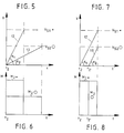
- FIGS. 5 to 8 The advantages of the measures and features according to the invention are clearly illustrated in FIGS. 5 to 8, in which the acceleration phases of the shears for two different rolling stock speeds and rolling stock cross sections are recorded.
- the symbol of a small dot ( . ) was chosen for small rolled sections and the symbol of a large circle (O) for large rolled sections.
- FIGS. 5 and 6 show the raising of the scissors, as is customary in the prior art.
- a steep acceleration path (12) with the angle ( ⁇ 1 ) and for the slow speed (v S2 . ) Results for the high speed (v S1 . )
- a small rolling stock cross section ( . ) O) with a larger cross section (O) a correspondingly flatter acceleration path (13) with the smaller angle ( ⁇ 2 ).
- FIGS. 7 and 8 have the same rolling stock cross sections and shear speeds of Figures 5 and 6 die corresponding acceleration paths and the resulting resulting moments recorded, which vary according to the arrangement a manual transmission between the scissors gear and Result drive motor.
Landscapes
- Engineering & Computer Science (AREA)
- Mechanical Engineering (AREA)
- Metal Rolling (AREA)
- Shearing Machines (AREA)
- Conveying And Assembling Of Building Elements In Situ (AREA)
- Manufacture Of Motors, Generators (AREA)
- Sawing (AREA)
- Control Of Metal Rolling (AREA)
Claims (8)
- Procédé d'exploitation de cisailles rotatives d'éboutage en service marche-arrêt sur matières à laminer à différentes vitesses sur trains continus à fils, trains à fines tôles, trains de laminage intermédiaires et trains à billettes, selon lequel les cisailles d'éboutage, dont l'engrenage (7) est relié à un moteur d'entraínement (9) par un accouplement (10), qui est accéléré de la position de repos à env. la vitesse de laminage et qui une fois que la coupe est réalisée est à nouveau stoppé, caractérisé en ce qu' une transmission à changement de vitesses (8) est disposée entre l'engrenage des cisailles (7) et le moteur d'entraínement (9), sachant que l'engrenage des cisailles (7) et la transmission à changement de vitesses (8) ainsi que la transmission à changement de vitesses (8) et le moteur d'entraínement (9) sont respectivement reliés entre eux par un accouplement (10) rigide à la torsion, à l'aide duquel la combinaison des phases de travail suivantes reliées entre elles est exécutée :a) Démarrage des cisailles avec un faible couple d'entraínement (M1) (env. 10% du couple nominal = 0,1 Mn) durant le court laps de temps qui est nécessaire à l'élimination de l'engrenage et du jeu de l'accouplement, en moyenne durant un laps de temps de 10 ms env., ensuiteb) accélération constante des cisailles à la vitesse de consigne des cisailles (vs) avec une pente maximum et un couple maximum d'accélération (M2) pour toutes les vitesses et sections de matières à laminer, la vitesse de consigne des cisailles (vs) étant choisie plus grande que la vitesse de la matière à laminer (vM) (cisailles glissés en avant),c) Commencement de la coupe peu avant l'atteinte de la vitesse de consigne des cisailles (vs) à un moment t3, auquel la vitesse des cisailles est déjà supérieure à celle de la matière à laminer (vM),d) surveillance automatique de la vitesse circonférentielle de la lame des cisailles pendant la coupe afin de maintenir un glissement optimal en avant des cisailles.
- Procédé selon la revendication 1, caractérisé en ce que les signaux de mesure du contrôle de la vitesse circonférentielle de la lame des cisailles soient utilisés pour la régulation de la vitesse circonférentielle de la lame des cisailles.
- Procédé selon la revendication 1 ou 2, caractérisé en ce que pour l'adaptation de l'accélération maximum à la vitesse de consigne requise des cisailles (vs) le point de départ t1 des cisailles soit déplacé de façon correspondante et par suite le chemin d'accélération soit modifié conformément.
- Procédé selon la revendication 1, 2 ou 3, caractérisé en ce qu'en cas de courtes distances d'accélération, les lames des couteaux se trouvent dans une position d'attente avantageuse du point de vue thermique jusqu'à peu avant la coupe.
- Appareillage pour l'exécution du procédé selon l'une ou plusieurs revendications précédentes avec des cisailles rotatives d'éboutage, dont l'engrenage (7) est relié à un moteur d'entraínement (9) par un accouplement (10), caractérisé en ce qu'une transmission à changement de vitesses (8) soit disposée entre l'engrenage des cisailles (7) et le moteur d'entraínement (9), l'engrenage des cisailles (7) et la transmission à changement de vitesses (8) ainsi que la transmission à changement de vitesses (8) et le moteur d'entraínement (9) soient reliés respectivement entre eux par un accouplement résistant à la torsion (10, 11).
- Appareillage selon la revendication 5, caractérisé en ce qu'un appareil de mesure soit disposé sur les cisailles pour le contrôle automatique de la vitesse circonférentielle de la lame de cisailles, dont les signaux de mesure vont dans une unité de réglage pour la commande de la vitesse circonférentielle des lames de cisailles pendant la coupe.
- Appareillage selon la revendication 5 ou 6, caractérisé en ce que la transmission à changement de vitesses (8) dispose de plus de deux vitesses.
- Appareillage selon la revendication 5 ou 6, caractérisé en ce que la transmission à changement de vitesses (8) soit commutable en continu.
Applications Claiming Priority (2)
| Application Number | Priority Date | Filing Date | Title |
|---|---|---|---|
| DE19633308A DE19633308A1 (de) | 1996-08-19 | 1996-08-19 | Verfahren und Vorrichtung zum Betrieb von rotierenden Anlaufscheren |
| DE19633308 | 1996-08-19 |
Publications (2)
| Publication Number | Publication Date |
|---|---|
| EP0824984A1 EP0824984A1 (fr) | 1998-02-25 |
| EP0824984B1 true EP0824984B1 (fr) | 1999-12-22 |
Family
ID=7802969
Family Applications (1)
| Application Number | Title | Priority Date | Filing Date |
|---|---|---|---|
| EP97113088A Expired - Lifetime EP0824984B1 (fr) | 1996-08-19 | 1997-07-30 | Procédé et appareillage pour l'exploitation de cisailles rotatives d'éboutage |
Country Status (4)
| Country | Link |
|---|---|
| US (2) | US6164175A (fr) |
| EP (1) | EP0824984B1 (fr) |
| AT (1) | ATE187912T1 (fr) |
| DE (2) | DE19633308A1 (fr) |
Families Citing this family (4)
| Publication number | Priority date | Publication date | Assignee | Title |
|---|---|---|---|---|
| US7823492B2 (en) * | 2005-06-09 | 2010-11-02 | Siemens Industry, Inc. | Dual ratio drive for rotary shear |
| US8336433B2 (en) * | 2009-07-21 | 2012-12-25 | Siemens Industry, Inc. | Rotary shear |
| JP6960794B2 (ja) * | 2017-07-29 | 2021-11-05 | 株式会社Rej | ロータリーシャー制御装置 |
| JP7722233B2 (ja) * | 2022-03-23 | 2025-08-13 | 株式会社デンソー | 切断加工システム |
Family Cites Families (14)
| Publication number | Priority date | Publication date | Assignee | Title |
|---|---|---|---|---|
| DE1004451B (de) * | 1953-01-31 | 1957-03-14 | Hallden Machine Company | Fliegende Schere zum Unterteilen von laufendem Schneidgut in Abschnitte von einstellbaren Laengen mit zwei unabhaengig voneinander in Schneidstellung zueinander kommenden Schneidmessern |
| DE2003922B2 (de) * | 1970-01-29 | 1971-08-26 | Ungerer Geb Dollinger | Wechselgetriebe zum antrieb einer fliegenden schere |
| FR2120160B1 (fr) * | 1970-12-31 | 1973-06-08 | Kawasaki Heavy Ind Ltd | |
| DE3020084A1 (de) * | 1980-05-27 | 1981-12-03 | Schloemann-Siemag AG, 4000 Düsseldorf | Verfahren zum schopfen und probenschneiden an mit hoher geschwindigkeit laufendem walzgut sowie anlauf- oder durchlauftrommelschere zur ausuebung des verfahrens |
| DE3042171A1 (de) * | 1980-11-08 | 1982-06-16 | Hoestemberghe & Klütsch GmbH, 6630 Saarlouis | Schere zum schneiden von draht oder stabstahl |
| JPS6179515A (ja) * | 1984-09-25 | 1986-04-23 | Mitsubishi Heavy Ind Ltd | 板体の定寸切断装置 |
| JPS6179516A (ja) * | 1984-09-28 | 1986-04-23 | Ishikawajima Harima Heavy Ind Co Ltd | フライングシヤ |
| US4771667A (en) * | 1986-09-02 | 1988-09-20 | Metl-Saw System Inc | Precision metal cutting saw and assembly |
| US4926728A (en) * | 1986-09-05 | 1990-05-22 | Contour Saws, Inc. | Band saw for cutting shaped pieces of bar stock |
| US5260541A (en) * | 1990-12-10 | 1993-11-09 | Hitachi, Ltd. | Crop shear apparatus and crop shear equipment |
| DE59105799D1 (de) * | 1991-09-17 | 1995-07-27 | Gfm Fertigungstechnik | Rotations- oder Lenkhebelschere. |
| EP0638375B1 (fr) * | 1993-07-13 | 1996-11-13 | Siemens Aktiengesellschaft | Procédé et dispositif pour la surveillance de l'apparition du broutage dans des commandes symétriques doubles de cages de laminoir |
| AT405619B (de) * | 1995-04-25 | 1999-10-25 | Voest Alpine Ind Anlagen | Walzgerüst |
| US5664472A (en) * | 1995-06-29 | 1997-09-09 | Mitsubishi Denki Kabushiki Kaisha | Cutter apparatus for coil conductor |
-
1996
- 1996-08-19 DE DE19633308A patent/DE19633308A1/de not_active Withdrawn
-
1997
- 1997-07-30 DE DE59700876T patent/DE59700876D1/de not_active Expired - Fee Related
- 1997-07-30 AT AT97113088T patent/ATE187912T1/de not_active IP Right Cessation
- 1997-07-30 EP EP97113088A patent/EP0824984B1/fr not_active Expired - Lifetime
- 1997-08-18 US US08/914,873 patent/US6164175A/en not_active Expired - Fee Related
-
2000
- 2000-10-12 US US09/689,985 patent/US6349585B1/en not_active Expired - Fee Related
Also Published As
| Publication number | Publication date |
|---|---|
| US6349585B1 (en) | 2002-02-26 |
| ATE187912T1 (de) | 2000-01-15 |
| US6164175A (en) | 2000-12-26 |
| EP0824984A1 (fr) | 1998-02-25 |
| DE19633308A1 (de) | 1998-02-26 |
| DE59700876D1 (de) | 2000-01-27 |
Similar Documents
| Publication | Publication Date | Title |
|---|---|---|
| EP1776205B1 (fr) | Procede de soudage par friction d'elements constitutifs | |
| DE102012102527B4 (de) | Pressenantrieb mit mehreren Arbeitsbereichen | |
| DE1402211A1 (de) | Werkzeugmaschine mit mechanischem Schneidwerkzeugwechsler | |
| DE3900734C2 (de) | Vorrichtung zum Richten und Abschneiden von Runddraht oder dergleichen | |
| DE102010014893A1 (de) | Vorrichtung zum Bearbeiten von Bodenoberflächen | |
| EP1382238B1 (fr) | Dispositif agricole avec variateur continu à poulies coniques | |
| DE2823610A1 (de) | Pendelschere | |
| EP1642051B1 (fr) | Procede de commande et de regulation d'un frein d'engrenage dans une boite de vitesses automatique d'un vehicule automobile | |
| EP0824984B1 (fr) | Procédé et appareillage pour l'exploitation de cisailles rotatives d'éboutage | |
| DE2461421A1 (de) | Sicherheitsgangschaltung an einem schneeraeumfahrzeug | |
| EP1099501B1 (fr) | Cisaille volante pour couper des bandes laminées | |
| DE2911765A1 (de) | Kaltschere, insbesondere zum schneiden von knueppeln und staeben | |
| EP0532820B1 (fr) | Cisaille à tambour ou à levier | |
| DE2306137C3 (de) | Vorrichtung zum Gewindeschneiden auf einer Drehmaschine | |
| DE6930577U (de) | Kupplungsmotor. | |
| EP1118409A1 (fr) | Cisaille volante | |
| DE102019102881B4 (de) | Verfahren und Steuergerät zum Betreiben eines Antriebstrangs mit Haupt- und Zusatzantrieb und Überlagerungsgetriebe | |
| DE2818840C2 (de) | Zustelleinrichtung für die Schleifbearbeitung von planen oder sphärischen Flächen | |
| DE2718794A1 (de) | Verfahren und vorrichtung zum abscheren von warmwalzbaendern | |
| DE597523C (fr) | ||
| DE2922941A1 (de) | Kaltpilgerwalzwerk | |
| DE2130669A1 (de) | Vorrichtung zum stillsetzen und/oder anspinnen einer offen-end-spinnvorrichtung | |
| EP0784174A2 (fr) | Armature avec un servomoteur électrique | |
| DE2638120C3 (de) | Karde | |
| DE2919068A1 (de) | Durch eine brennkraftmaschine angetriebener rasenmaeher |
Legal Events
| Date | Code | Title | Description |
|---|---|---|---|
| PUAI | Public reference made under article 153(3) epc to a published international application that has entered the european phase |
Free format text: ORIGINAL CODE: 0009012 |
|
| 17P | Request for examination filed |
Effective date: 19970813 |
|
| AK | Designated contracting states |
Kind code of ref document: A1 Designated state(s): AT DE GB IT SE |
|
| AX | Request for extension of the european patent |
Free format text: AL;LT;LV;RO;SI |
|
| AKX | Designation fees paid |
Free format text: AT DE GB IT SE |
|
| RBV | Designated contracting states (corrected) |
Designated state(s): AT DE GB IT SE |
|
| GRAG | Despatch of communication of intention to grant |
Free format text: ORIGINAL CODE: EPIDOS AGRA |
|
| 17Q | First examination report despatched |
Effective date: 19990216 |
|
| GRAG | Despatch of communication of intention to grant |
Free format text: ORIGINAL CODE: EPIDOS AGRA |
|
| GRAG | Despatch of communication of intention to grant |
Free format text: ORIGINAL CODE: EPIDOS AGRA |
|
| GRAH | Despatch of communication of intention to grant a patent |
Free format text: ORIGINAL CODE: EPIDOS IGRA |
|
| GRAH | Despatch of communication of intention to grant a patent |
Free format text: ORIGINAL CODE: EPIDOS IGRA |
|
| GRAA | (expected) grant |
Free format text: ORIGINAL CODE: 0009210 |
|
| AK | Designated contracting states |
Kind code of ref document: B1 Designated state(s): AT DE GB IT SE |
|
| REF | Corresponds to: |
Ref document number: 187912 Country of ref document: AT Date of ref document: 20000115 Kind code of ref document: T |
|
| REF | Corresponds to: |
Ref document number: 59700876 Country of ref document: DE Date of ref document: 20000127 |
|
| ITF | It: translation for a ep patent filed | ||
| GBT | Gb: translation of ep patent filed (gb section 77(6)(a)/1977) |
Effective date: 20000302 |
|
| RAP2 | Party data changed (patent owner data changed or rights of a patent transferred) |
Owner name: SMS DEMAG AG |
|
| PLBE | No opposition filed within time limit |
Free format text: ORIGINAL CODE: 0009261 |
|
| STAA | Information on the status of an ep patent application or granted ep patent |
Free format text: STATUS: NO OPPOSITION FILED WITHIN TIME LIMIT |
|
| 26N | No opposition filed | ||
| PGFP | Annual fee paid to national office [announced via postgrant information from national office to epo] |
Ref country code: GB Payment date: 20010614 Year of fee payment: 5 |
|
| PGFP | Annual fee paid to national office [announced via postgrant information from national office to epo] |
Ref country code: SE Payment date: 20010702 Year of fee payment: 5 |
|
| PGFP | Annual fee paid to national office [announced via postgrant information from national office to epo] |
Ref country code: AT Payment date: 20010704 Year of fee payment: 5 |
|
| PGFP | Annual fee paid to national office [announced via postgrant information from national office to epo] |
Ref country code: DE Payment date: 20010713 Year of fee payment: 5 |
|
| REG | Reference to a national code |
Ref country code: GB Ref legal event code: IF02 |
|
| PG25 | Lapsed in a contracting state [announced via postgrant information from national office to epo] |
Ref country code: GB Free format text: LAPSE BECAUSE OF NON-PAYMENT OF DUE FEES Effective date: 20020730 Ref country code: AT Free format text: LAPSE BECAUSE OF NON-PAYMENT OF DUE FEES Effective date: 20020730 |
|
| PG25 | Lapsed in a contracting state [announced via postgrant information from national office to epo] |
Ref country code: SE Free format text: LAPSE BECAUSE OF NON-PAYMENT OF DUE FEES Effective date: 20020731 |
|
| PG25 | Lapsed in a contracting state [announced via postgrant information from national office to epo] |
Ref country code: DE Free format text: LAPSE BECAUSE OF NON-PAYMENT OF DUE FEES Effective date: 20030201 |
|
| EUG | Se: european patent has lapsed | ||
| GBPC | Gb: european patent ceased through non-payment of renewal fee |
Effective date: 20020730 |
|
| PG25 | Lapsed in a contracting state [announced via postgrant information from national office to epo] |
Ref country code: IT Free format text: LAPSE BECAUSE OF NON-PAYMENT OF DUE FEES;WARNING: LAPSES OF ITALIAN PATENTS WITH EFFECTIVE DATE BEFORE 2007 MAY HAVE OCCURRED AT ANY TIME BEFORE 2007. THE CORRECT EFFECTIVE DATE MAY BE DIFFERENT FROM THE ONE RECORDED. Effective date: 20050730 |