EP0825058A2 - Verfahren zum Schalten eines Doppelkupplungsgetriebes und Doppelkupplungsgetriebe mit Synchronisiereinrichtung - Google Patents
Verfahren zum Schalten eines Doppelkupplungsgetriebes und Doppelkupplungsgetriebe mit Synchronisiereinrichtung Download PDFInfo
- Publication number
- EP0825058A2 EP0825058A2 EP97111397A EP97111397A EP0825058A2 EP 0825058 A2 EP0825058 A2 EP 0825058A2 EP 97111397 A EP97111397 A EP 97111397A EP 97111397 A EP97111397 A EP 97111397A EP 0825058 A2 EP0825058 A2 EP 0825058A2
- Authority
- EP
- European Patent Office
- Prior art keywords
- clutch
- speed
- gear
- input shaft
- transmission input
- Prior art date
- Legal status (The legal status is an assumption and is not a legal conclusion. Google has not performed a legal analysis and makes no representation as to the accuracy of the status listed.)
- Granted
Links
Images




Classifications
-
- F—MECHANICAL ENGINEERING; LIGHTING; HEATING; WEAPONS; BLASTING
- F16—ENGINEERING ELEMENTS AND UNITS; GENERAL MEASURES FOR PRODUCING AND MAINTAINING EFFECTIVE FUNCTIONING OF MACHINES OR INSTALLATIONS; THERMAL INSULATION IN GENERAL
- F16H—GEARING
- F16H61/00—Control functions within control units of change-speed- or reversing-gearings for conveying rotary motion ; Control of exclusively fluid gearing, friction gearing, gearings with endless flexible members or other particular types of gearing
- F16H61/68—Control functions within control units of change-speed- or reversing-gearings for conveying rotary motion ; Control of exclusively fluid gearing, friction gearing, gearings with endless flexible members or other particular types of gearing specially adapted for stepped gearings
- F16H61/684—Control functions within control units of change-speed- or reversing-gearings for conveying rotary motion ; Control of exclusively fluid gearing, friction gearing, gearings with endless flexible members or other particular types of gearing specially adapted for stepped gearings without interruption of drive
- F16H61/688—Control functions within control units of change-speed- or reversing-gearings for conveying rotary motion ; Control of exclusively fluid gearing, friction gearing, gearings with endless flexible members or other particular types of gearing specially adapted for stepped gearings without interruption of drive with two inputs, e.g. selection of one of two torque-flow paths by clutches
-
- F—MECHANICAL ENGINEERING; LIGHTING; HEATING; WEAPONS; BLASTING
- F16—ENGINEERING ELEMENTS AND UNITS; GENERAL MEASURES FOR PRODUCING AND MAINTAINING EFFECTIVE FUNCTIONING OF MACHINES OR INSTALLATIONS; THERMAL INSULATION IN GENERAL
- F16H—GEARING
- F16H61/00—Control functions within control units of change-speed- or reversing-gearings for conveying rotary motion ; Control of exclusively fluid gearing, friction gearing, gearings with endless flexible members or other particular types of gearing
- F16H61/04—Smoothing ratio shift
- F16H61/0403—Synchronisation before shifting
-
- F—MECHANICAL ENGINEERING; LIGHTING; HEATING; WEAPONS; BLASTING
- F16—ENGINEERING ELEMENTS AND UNITS; GENERAL MEASURES FOR PRODUCING AND MAINTAINING EFFECTIVE FUNCTIONING OF MACHINES OR INSTALLATIONS; THERMAL INSULATION IN GENERAL
- F16H—GEARING
- F16H61/00—Control functions within control units of change-speed- or reversing-gearings for conveying rotary motion ; Control of exclusively fluid gearing, friction gearing, gearings with endless flexible members or other particular types of gearing
- F16H61/04—Smoothing ratio shift
- F16H61/0403—Synchronisation before shifting
- F16H2061/0411—Synchronisation before shifting by control of shaft brakes
-
- F—MECHANICAL ENGINEERING; LIGHTING; HEATING; WEAPONS; BLASTING
- F16—ENGINEERING ELEMENTS AND UNITS; GENERAL MEASURES FOR PRODUCING AND MAINTAINING EFFECTIVE FUNCTIONING OF MACHINES OR INSTALLATIONS; THERMAL INSULATION IN GENERAL
- F16H—GEARING
- F16H61/00—Control functions within control units of change-speed- or reversing-gearings for conveying rotary motion ; Control of exclusively fluid gearing, friction gearing, gearings with endless flexible members or other particular types of gearing
- F16H61/04—Smoothing ratio shift
- F16H2061/0425—Bridging torque interruption
-
- F—MECHANICAL ENGINEERING; LIGHTING; HEATING; WEAPONS; BLASTING
- F16—ENGINEERING ELEMENTS AND UNITS; GENERAL MEASURES FOR PRODUCING AND MAINTAINING EFFECTIVE FUNCTIONING OF MACHINES OR INSTALLATIONS; THERMAL INSULATION IN GENERAL
- F16H—GEARING
- F16H2306/00—Shifting
- F16H2306/14—Skipping gear shift
-
- F—MECHANICAL ENGINEERING; LIGHTING; HEATING; WEAPONS; BLASTING
- F16—ENGINEERING ELEMENTS AND UNITS; GENERAL MEASURES FOR PRODUCING AND MAINTAINING EFFECTIVE FUNCTIONING OF MACHINES OR INSTALLATIONS; THERMAL INSULATION IN GENERAL
- F16H—GEARING
- F16H2306/00—Shifting
- F16H2306/40—Shifting activities
- F16H2306/44—Removing torque from current gears
-
- F—MECHANICAL ENGINEERING; LIGHTING; HEATING; WEAPONS; BLASTING
- F16—ENGINEERING ELEMENTS AND UNITS; GENERAL MEASURES FOR PRODUCING AND MAINTAINING EFFECTIVE FUNCTIONING OF MACHINES OR INSTALLATIONS; THERMAL INSULATION IN GENERAL
- F16H—GEARING
- F16H2306/00—Shifting
- F16H2306/40—Shifting activities
- F16H2306/48—Synchronising of new gear
-
- F—MECHANICAL ENGINEERING; LIGHTING; HEATING; WEAPONS; BLASTING
- F16—ENGINEERING ELEMENTS AND UNITS; GENERAL MEASURES FOR PRODUCING AND MAINTAINING EFFECTIVE FUNCTIONING OF MACHINES OR INSTALLATIONS; THERMAL INSULATION IN GENERAL
- F16H—GEARING
- F16H2306/00—Shifting
- F16H2306/40—Shifting activities
- F16H2306/52—Applying torque to new gears
-
- F—MECHANICAL ENGINEERING; LIGHTING; HEATING; WEAPONS; BLASTING
- F16—ENGINEERING ELEMENTS AND UNITS; GENERAL MEASURES FOR PRODUCING AND MAINTAINING EFFECTIVE FUNCTIONING OF MACHINES OR INSTALLATIONS; THERMAL INSULATION IN GENERAL
- F16H—GEARING
- F16H3/00—Toothed gearings for conveying rotary motion with variable gear ratio or for reversing rotary motion
- F16H3/006—Toothed gearings for conveying rotary motion with variable gear ratio or for reversing rotary motion power being selectively transmitted by parallel flow paths, e.g. dual clutch transmissions
-
- F—MECHANICAL ENGINEERING; LIGHTING; HEATING; WEAPONS; BLASTING
- F16—ENGINEERING ELEMENTS AND UNITS; GENERAL MEASURES FOR PRODUCING AND MAINTAINING EFFECTIVE FUNCTIONING OF MACHINES OR INSTALLATIONS; THERMAL INSULATION IN GENERAL
- F16H—GEARING
- F16H3/00—Toothed gearings for conveying rotary motion with variable gear ratio or for reversing rotary motion
- F16H3/02—Toothed gearings for conveying rotary motion with variable gear ratio or for reversing rotary motion without gears having orbital motion
- F16H3/08—Toothed gearings for conveying rotary motion with variable gear ratio or for reversing rotary motion without gears having orbital motion exclusively or essentially with continuously meshing gears, that can be disengaged from their shafts
- F16H3/087—Toothed gearings for conveying rotary motion with variable gear ratio or for reversing rotary motion without gears having orbital motion exclusively or essentially with continuously meshing gears, that can be disengaged from their shafts characterised by the disposition of the gears
- F16H3/089—Toothed gearings for conveying rotary motion with variable gear ratio or for reversing rotary motion without gears having orbital motion exclusively or essentially with continuously meshing gears, that can be disengaged from their shafts characterised by the disposition of the gears all of the meshing gears being supported by a pair of parallel shafts, one being the input shaft and the other the output shaft, there being no countershaft involved
-
- Y—GENERAL TAGGING OF NEW TECHNOLOGICAL DEVELOPMENTS; GENERAL TAGGING OF CROSS-SECTIONAL TECHNOLOGIES SPANNING OVER SEVERAL SECTIONS OF THE IPC; TECHNICAL SUBJECTS COVERED BY FORMER USPC CROSS-REFERENCE ART COLLECTIONS [XRACs] AND DIGESTS
- Y10—TECHNICAL SUBJECTS COVERED BY FORMER USPC
- Y10T—TECHNICAL SUBJECTS COVERED BY FORMER US CLASSIFICATION
- Y10T74/00—Machine element or mechanism
- Y10T74/19—Gearing
- Y10T74/19219—Interchangeably locked
- Y10T74/19233—Plurality of counter shafts
-
- Y—GENERAL TAGGING OF NEW TECHNOLOGICAL DEVELOPMENTS; GENERAL TAGGING OF CROSS-SECTIONAL TECHNOLOGIES SPANNING OVER SEVERAL SECTIONS OF THE IPC; TECHNICAL SUBJECTS COVERED BY FORMER USPC CROSS-REFERENCE ART COLLECTIONS [XRACs] AND DIGESTS
- Y10—TECHNICAL SUBJECTS COVERED BY FORMER USPC
- Y10T—TECHNICAL SUBJECTS COVERED BY FORMER US CLASSIFICATION
- Y10T74/00—Machine element or mechanism
- Y10T74/19—Gearing
- Y10T74/19219—Interchangeably locked
- Y10T74/19284—Meshing assisters
Definitions
- the invention relates to a method for shifting a dual clutch transmission with two Transmission input shafts and a transmission output shaft, with each input shaft Friction clutch is assigned and in the initial state one of the two clutches in Holding state transmits an engine torque, and the other clutch is open.
- the invention further relates to a dual clutch transmission with two Transmission input shafts and a transmission output shaft for operation according to one Switching method according to the invention.
- the load-shifting transmissions include dual clutch transmissions in the style of the PDK (Porsche dual clutch transmission). It is a transmission with two Transmission input shafts that work on a common transmission output shaft, wherein As a rule, the two transmission input shafts are arranged coaxially to one another. On the A gear input shaft is usually the gears for even gears and on the other transmission input shaft the gears for the odd-numbered gears.
- Each of the two transmission input shafts can have its own, independent clutch in sliding or static friction with the internal combustion engine (motor) get connected.
- central synchronizers for the whole transmission with hydraulic actuation the problems mentioned when switching the to avoid conventional locking synchronizer rings.
- the central synchronization is one Central synchronizing unit arranged so that, for example, a transmission output shaft can be braked or driven. Additional mechanical, hydraulic or electric drives necessary, which is too unacceptable in normal car construction high costs and weights.
- the invention is therefore based on the object of a method for switching a To create dual clutch transmission, as well as a double clutch transmission Operation according to the inventive method, which is completely without influencing the Power actuator of the respective internal combustion engine can get by (no Engine management), and which can be operated at least in principle in such a way that a Removing gears with the clutch fully open and therefore completely jerk-free can.
- the translation of the Friction gear i.e. from transmission output shaft to transmission input shaft, is smaller than the smallest gear arranged on the gearbox input shaft (higher Input shaft speed than in the lowest gear).
- the "one" transmission input shaft is said to be in each case the load transferring at the time of the planned gear shift, i.e. a Moment leading wave can be understood.
- Under the "other" transmission input shaft becomes the shaft that initially carries the gear to be shifted and rotates freely Understood. This wave is accordingly also called “free” in the context of this description.
- Gearbox input shaft designated.
- the method according to the invention therefore presupposes that the other, free Gearbox input shaft initially to a synchronous speed using suitable means is brought so that an engagement of the gear is made possible.
- the synchronization aid according to the invention such as it is described in the device claims is one possibility. Also through clever control of the associated clutch of the other transmission input shaft can synchronous speed is reached and gear engagement is made possible.
- the speed is at least one Clutch to a value close to the synchronous speed in the sliding friction range regulate.
- the speed controller in particular provided to specify a target speed to a speed controller, or a target speed for to specify the corresponding clutch, which results from the synchronous speed plus or minus a defined slip speed. This ensures that the regulated clutch is in the sliding friction state, thereby blocking the Gear can be safely excluded.
- the target speed of the motor-side half is provided in particular of the clutch by measuring the operating condition of the vehicle, i.e. Train operation or overrun operation on the one hand and the planned switching, i.e. Upshift or Downshifting, on the other hand, is taken into account.
- the target speed is determined as a function of the operating state of the vehicle and the type of gearshift as defined in the following table:
- Operating mode of the vehicle Circuit type Target speed for the slip speed controller of one clutch Train operation Upshift Synchronous speed of the one transmission input shaft + slip Train operation Downshift Synchronous speed of the other transmission input shaft + slip Push operation Upshift Synchronous speed of the other transmission input shaft - slip Push operation Downshift Synchronous speed of one transmission input shaft - slip
- the target speed is dimensioned as defined in the table below is: Operating mode of the vehicle Circuit type Target speed for the speed controller of the other clutch Train operation Upshift Synchronous speed of the one transmission input shaft + slip Train operation Downshift Synchronous speed of the other transmission input shaft + slip Push operation Upshift Synchronous speed of the other transmission input shaft - slip Push operation Downshift Synchronous speed of one transmission input shaft - slip
- slip is to be understood as a defined speed difference, its absolute value can be, for example, 50 rpm.
- the target speed refers always on the motor side half of the coupling.
- the circuit type is used when carrying out the method according to the invention "Upshifting" is unproblematic both in train operation and in push operation.
- the free Transmission input shaft, i.e. the wave carrying the target gear must in the worst case be accelerated from standstill to a synchronous speed, which is definitely below the current engine speed.
- By appropriate control of the assigned “Other” clutch can therefore be achieved in any case, the synchronous speed that the Entry of the target gear allowed.
- the additionally provided Synchronization help can be used.
- Another option is after closing the clutch assigned to the free transmission input shaft ("other" clutch) by means of Engine management to generate an increase in speed of the previously driven engine, to accelerate the free transmission input shaft.
- This mode of operation has the disadvantage that that on the one hand it is a prerequisite that the one clutch (clutch of the Output gear) is open to complete separation of the transmission and engine achieve, and that, on the other hand, the sudden increase in engine speed is psychologically disadvantageous.
- the latter is because the operating mode "downshift with Overrun "generally occurs on valley runs where there is a sudden Increased engine speed unsettled the driver.
- FIG. 1 schematically shows a dual clutch transmission 10 according to the invention, which is driven by an internal combustion engine, which is symbolized by its crankshaft 12.
- Two clutches K 1 and K 2 have a common outer clutch basket 14 and are arranged concentrically next to one another.
- a (first) transmission input shaft E 1 and another (second) transmission input shaft E 2 are connected to the respective friction plate 16 1 and 16 2 .
- the transmission input shaft E 2 is designed as a hollow shaft and surrounds the transmission input shaft E 1 .
- a total of six gear pairs 1 to 6 represent the individual gears.
- the drive wheels of gears 5 and 2 are firmly connected to the respective transmission input shaft, while the drive wheels of gears 1, 3, 4 and 6 are designed as needle-bearing idler gears which can be actuated by claws via sliding sleeves 18 1 and 18 2 .
- a transmission output shaft A carries a total of six output gears, the output gears of gears 5 and 2 being designed as idler gears and can be shifted via a sliding sleeve 18 A.
- the driven wheels of gears 1, 3, 4 and 6 are firmly connected to the transmission output shaft A.
- the power flow runs via the closed clutch K 2 , the transmission input shaft E 2 , the sliding sleeve 18 2 , the drive gear of the first gear on the driven gear of the first gear on the transmission output shaft A.
- the clutch is the one in the initial state Transfers engine power, i.e. essentially in the engaged state, i.e. in the Stiction, is the "one" clutch, while the one belonging to the target gear Coupling is the "other" coupling.
- the lower gear is always the one with the higher gearbox input speed.
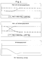
- Figure 2 shows the upshift in the train, i.e. the motor delivers a positive torque The gear.
- the clutch of the smaller gear is in static friction, the larger one Gear is already engaged, but the associated clutch is still open.
- a small slip gear is now a slip control.
- the clutch pressure and / or the clutch travel is reduced so far that the clutch with completely low slip slips.
- the slip is then controlled by controller functions (Target speed specification) maintained, the control unit previously from the fact that the engine speed in slip operation is higher than the transmission input speed, the Can conclude that the engine is in train mode.
- the clutch of the big one Ganges is now closed in a ramp (initially uncontrolled).
- the big hall takes on more and more engine torque.
- the clutch opens due to the slip controller of the small aisle to the same extent. When the big gear the full engine torque has reached, the clutch of the small gear is fully open.
- the small gear can now without a torque reaction, i.e. without sacrificing comfort from which Drive train can be removed.
- control strategy can be reversed in accordance with main claim 2.
- the engine initially rotates at the (higher) speed of the small one Ganges.
- the larger gear is not yet engaged.
- the other clutch is open, the associated transmission input shaft ideally does not rotate, in practice it turns slightly due to unavoidable drag torque.
- the clutch of the major aisle is now closed somewhat.
- the clutch torque is the The speed of the freely rotating transmission input shaft of the target gear is increased.
- At The high gear is engaged when the synchronous speed is reached. If the The clutch is fully opened again at the synchronous speed of the large gear.
- the aisle is now inserted.
- the synchronous speed of the large gear initially is exceeded and the clutch is then opened. When it runs out the transmission input shaft will come from higher speeds Reach synchronous speed again. If the leakage is not fast enough, it can a friction brake can be used, which is used as an additional synchronizing aid can be.
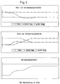
- Figures 3 and 7 show analogously the conditions for the upshift in overrun. How Figure 3 shows, the clutch of the smaller gear is initially closed, the larger Gear is engaged, but the associated clutch is still open. The engine delivers negative moment, i.e. it works as an engine brake. As with the previous ones Switching operations explained, the clutch of the small gear is brought into the sliding state, i.e. the clutch pressure and / or the clutch travel is reduced so far until the clutch slips with little slip (synchronous speed - 50 rpm).
- the clutch of the low gear transmits - now in sliding friction - the whole Engine torque. From the fact that the engine speed in slip operation is less than the input shaft speed of the small gear, the system can deduce that the Engine is in overrun.
- the slip controller now keeps the speed just below the clutch for the low gear the speed of the large gear fixed.
- the clutch of the large gear now closes ramp-shaped, whereby the slip regulator of the small aisle is opened more and more. With the clutch of the small gear fully open, it can be removed.
- the clutch of the large gear closes in a ramp shape until static friction.
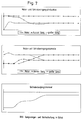
- FIGs 4 and 8 show the situation for the case "downshift in overrun".
- friction gear transmissions RG 1 and RG 2 are provided, each with a transmission input shaft E 1 or E 2 with the transmission output shaft A can connect.
- Each friction wheel transmission RG 1 or RG 2 each has a friction wheel which is arranged on the respective transmission input shaft E 1 or E 2 .
- These wheels have the reference numerals 20 1 and 20 2 .
- two friction wheels are arranged on the output shaft. These have the reference numerals 22 1 and 22 2 . Between the friction wheels 20 1 and 22 1 or 20 2 and 22 2 pairs of friction wheels are arranged, which are arranged on a pivotable carrier. These additional friction wheels are referred to as 23 1 , 24 1 ; 23 2 , 24 2 .
- the transmission input shaft E 2 must be accelerated when shifting down to the third gear, since a higher speed level is required in the third gear than in fourth gear. This can be accomplished by closing the RG 2 friction gear.
- the wheel pair 23 2/24 2 is pivoted into frictional contact, so that the voltage applied to the output shaft torque, which is of the entire rotational moment of inertia of the motor vehicle, converted fed to the output shaft (J RED, KFZ) can be used, the Accelerate transmission input shaft E 2 until a speed just above the synchronous speed of the target gear is reached.
- the friction pair is removed from the friction position and the egressing transmission input shaft E 2 can be shifted when the synchronous speed is passed.
- the friction wheel gear RG 1 is used analogously if, in overrun mode, ie with negative engine torque (engine brake), it is necessary to shift down from an odd gear to an even gear, for which purpose the gear input shaft E 1 must be accelerated. An example of this would be the downshift from third to second gear when descending.
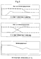
- Figures 5 and 9 show the last conceivable operating case, namely the downshift under train.
- the clutch of the large gear transmits - now in sliding friction - the total engine torque. From the fact that the engine speed in Slip mode is greater than the transmission shaft speed, the system can deduce that the engine is on the train.
- the clutch is first controlled by a ramp open.
- the slip controller keeps the speed of the clutch of the large gear just above the Synchronous speed of the small gear (target speed).
- the clutch of the small gear now closes in a ramp, causing the continuous slip controller to engage the large one Ganges keeps opening. With the clutch of the large gear fully open, this can be taken out.
- the clutch of the small gear closes in a ramp-like manner until stiction.
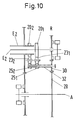
- Figure 10 shows an additional embodiment of an embodiment of the synchronizing device according to the invention using the reverse gear.
- the torque supplied by the output shaft A which is fed by the rotational moment of inertia of the entire vehicle reduced to shaft A, and which is to be used either to accelerate the transmission input shaft E 2 or the transmission input shaft E 1 , is transmitted via the gear 28 of the reverse gear R. on the pinion 30 used to reverse the direction of rotation.
- the shaft 32 connected to the pinion carries two friction wheels 25 1 and 25 2 . Since the direction of rotation has already been reversed, only one friction wheel 23 1 or 23 2 is necessary in order to accelerate the respectively selected transmission shaft via the friction wheels 20 1 or 20 2 .
- the pivotable friction wheels 23 1 and 23 2 are arranged on a common shaft.
- the driving friction wheels 25 1 and 25 2 like the friction wheels 23 1 and 23 2 used for coupling, can each be combined to form a roller, ie a cylindrical friction wheel.
- Construction space is saved by the embodiment created according to FIG. 10.
Landscapes
- Engineering & Computer Science (AREA)
- General Engineering & Computer Science (AREA)
- Mechanical Engineering (AREA)
- Control Of Transmission Device (AREA)
- Structure Of Transmissions (AREA)
Abstract
Description
- die andere Getriebewelle auf synchrone Drehzahl gebracht und dann der neue Gang eingelegt wird,
- die eine Kupplung durch einen Schlupfregler geregelt so weit geöffnet wird, daß sie bei einer Solldrehzahl ihrer motorseitigen Hälfte an der Gleitgrenze arbeitet,
- die andere Kupplung gesteuert geschlossen wird, bis die eine, durch den Schlupfregler an der Gleitgrenze betriebene Kupplung kein Moment mehr überträgt,
- die eine Kupplung dann voll geöffnet wird, so daß die andere Kupplung allein die Motorleistung überträgt, und
- der alte Gang im wesentlichen momentenfrei herausgenommen wird.
oder daß - die andere Getriebewelle auf synchrone Drehzahl gebracht und dann der neue Gang eingelegt wird,
- die andere Kupplung durch einen Schlupfregler geregelt so weit geschlossen wird, daß sie bei einer definierten, Solldrehzahl ihrer motorseitigen Hälfte an der Gleitgrenze arbeitet,
- die eine Kupplung gesteuert geöffnet wird, bis die andere, durch den Schlupfregler an der Gleitgrenze betriebene Kupplung das volle, aus Motorleistung und Drehzahl sich ergebende Moment überträgt,
- die andere Kupplung dann voll geschlossen wird, so daß die andere Kupplung allein die Motorleistung überträgt und
- wenn die eine Kupplung voll geöffnet ist, der alte Gang im wesentlichen momentenfrei herausgenommen wird.
- ein auf der zu synchronisierenden Getriebeeingangswelle angeordnetes Reibrad,
- ein auf der Getriebeabtriebswelle angeordnetes Reibrad, und
- ein auf einem schwenkbaren Träger angeordnetes Räderpaar, das in eine die beiden anderen Räder durch Reibschluß verbindende Lage geschwenkt werden kann.
| Betriebsart des Fahrzeuges | Schaltungsart | Solldrehzahl für den Schlupfdrehzahlregler der einen Kupplung |
| Zugbetrieb | Hochschaltung | Synchrondrehzahl der einen Getriebeeingangswelle + Schlupf |
| Zugbetrieb | Rückschaltung | Synchrondrehzahl der anderen Getriebeeingangswelle + Schlupf |
| Schubbetrieb | Hochschaltung | Synchrondrehzahl der anderen Getriebeeingangswelle - Schlupf |
| Schubbetrieb | Rückschaltung | Synchrondrehzahl der einen Getriebeeingangswelle - Schlupf |
| Betriebsart des Fahrzeuges | Schaltungsart | Solldrehzahl für den Drehzahlregler der anderen Kupplung |
| Zugbetrieb | Hochschaltung | Synchrondrehzahl der einen Getriebeeingangswelle + Schlupf |
| Zugbetrieb | Rückschaltung | Synchrondrehzahl der anderen Getriebeeingangswelle + Schlupf |
| Schubbetrieb | Hochschaltung | Synchrondrehzahl der anderen Getriebeeingangswelle - Schlupf |
| Schubbetrieb | Rückschaltung | Synchrondrehzahl der einen Getriebeeingangswelle - Schlupf |
- Figur 1
- schematisch dargestellt den Aufbau eines erfindungsgemäßen Doppelkupplungsgetriebes mit Synchronisiervorrichtung,
- Figur 2
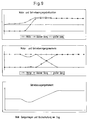
- den Verlauf von Motor- und Getriebeeingangsdrehzahlen, Motor- und Getriebeeingangsmomenten und Getriebeausgangsmoment für die Hochschaltung im Zug,
- Figur 3
- den Verlauf von Motor- und Getriebeeingangsdrehzahlen, Motor- und Getriebeeingangsmomenten und Getriebeausgangsmoment für die Hochschaltung im Schub,
- Figur 4
- den Verlauf von Motor- und Getriebeeingangsdrehzahlen, Motor- und Getriebeeingangsmomenten und Getriebeausgangsmoment für die Rückschaltung im Schub,
- Figur 5
- den Verlauf von Motor- und Getriebeeingangsdrehzahlen, Motor- und Getriebeeingangsmomenten und Getriebeausgangsmoment für die Rückschaltung im Zug,
- Figur 6
- die Darstellung von Figur 2, wobei zusätzlich das Gangeinlegen berücksichtigt ist,
- Figur 7
- die Darstellung von Figur 3, wobei zusätzlich das Gangeinlegen berücksichtigt ist,
- Figur 8
- die Darstellung von Figur 4, wobei zusätzlich das Gangeinlegen berücksichtigt ist,
- Figur 9
- die Darstellung von Figur 5, wobei zusätzlich das Gangeinlegen berücksichtigt ist, und
- Fig. 10
- eine alternative Ausführungsform der erfindungsgemäßen Synchronisiervorrichtung, bei der das die Drehrichtung bewirkende Ritzel des Rückwärtsganges zusätzlich angekoppelt ist.
- eine Kupplung in Haftreibung und die andere in Gleitreibung ist, oder
- beide Kupplungen in Gleitreibung sind.
- Ist eine Kupplung in Gleitreibung und ist die Motordrehzahl größer als die Getriebeeingangswellendrehzahl, dann wird positives (das Fahrzeug antreibende) Moment in die Getriebeeingangswelle eingespeist.
- Ist eine Kupplung in Gleitreibung und ist die Motordrehzahl kleiner als die Getriebeeingangswellendrehzahl, dann wird negatives (das Fahrzeug abbremsendes) Moment in die Getriebeeingangswelle eingespeist.
- Ist die Motordrehzahl größer als die Getriebeeingangsdrehzahl des kleineren Ganges, dann übertragen beide Getriebeeingangswellen positives Moment.
- Ist die Motordrehzahl kleiner als die Getriebeeingangsdrehzahl des größeren Ganges, dann übertragen beide Getriebeeingangswellen negatives Moment.
- Ist der kleinere Gang in Haftreibung, dann überträgt der größere Gang positives Moment.
- Keine Fahrzeugbeschleunigung während des Schaltvorgangs gezeichnet.
- Keine Momentenänderung des Motors durch Drehzahländerung bei Einleitung des Dauerschlupfs gezeichnet.
- Keine Momentenänderung durch Drehzahländerung des Motors während der Schaltvorgänge im Zug gezeichnet.
Claims (27)
- Verfahren zum Schalten eines Doppelkupplungsgetriebes (10) mit zwei Getriebeeingangswellen (E1, E2) und einer Getriebeabtriebswelle (A), wobei jeder Eingangswelle eine Reibkupplung (K1, K2) zugeordnet ist und im Ausgangszustand eine der beiden Kupplungen im Haftzustand ein Motormoment überträgt, und die andere Kupplung geöffnet ist, dadurch gekennzeichnet, daßdie andere Getriebewelle auf synchrone Drehzahl gebracht und dann der neue Gang eingelegt wird,die eine Kupplung durch einen Schlupfregler geregelt so weit geöffnet wird, daß sie bei einer Solldrehzahl ihrer motorseitigen Hältfe an der Gleitgrenze arbeitet,die andere Kupplung gesteuert geschlossen wird, bis die eine, durch den Schlupfregler an der Gleitgrenze betriebene Kupplung kein Moment mehr überträgt,die eine Kupplung dann voll geöffnet wird, so daß die andere Kupplung allein die Motorleistung überträgt, undder alte Gang im wesentlichen momentenfrei herausgenommen wird.
- Verfahren zum Schalten eines Doppelkupplungsgetriebes (10) mit zwei Getriebeeingangswellen (E1, E2) und einer Getriebeabtriebswelle (A), wobei jeder Eingangswelle eine Reibkupplung (K1, K2) zugeordnet ist, und im Ausgangszustand eine der beiden Kupplungen im Haftzustand ein Motormoment überträgt und die andere Kupplung geöffnet ist, dadurch gekennzeichnet, daßdie andere Getriebewelle auf synchrone Drehzahl gebracht und dann der neue Gang eingelegt wird,die andere Kupplung durch einen Schlupfregler geregelt so weit geschlossen wird, daß sie bei einer definierten, Solldrehzahl ihrer motorseitigen Hälfte an der Gleitgrenze arbeitet,die eine Kupplung gesteuert geöffnet wird, bis die andere, durch den Schlupfregler an der Gleitgrenze betriebene Kupplung das volle, aus Motorleistung und Drehzahl sich ergebende Moment überträgt,die andere Kupplung dann voll geschlossen wird, so daß die andere Kupplung allein die Motorleistung überträgt, undwenn die eine Kupplung voll geöffnet ist, der alte Gang im wesentlichen momentenfrei herausgenommen wird.
- Verfahren nach einem der Ansprüche 1 oder 2, dadurch gekennzeichnet, daß die Drehzahl der jeweils anderen, freien Getriebeeingangswelle mit Hilfe einer Synchronisiervorrichtung auf die passende synchrone Drehzahl beschleunigt oder abgebremst wird.
- Verfahren nach Anspruch 3, dadurch gekennzeichnet, daß die Synchronisiervorrichtung zum Beschleunigen der freien Getriebeeingangswelle (E1, E2) notwendiges Moment von der Getriebeabtriebswelle (A) abgreift.
- Verfahren nach Anspruch 4, dadurch gekennzeichnet, daß die Synchronisiervorrichtung die Getriebeabtriebswelle (A) mit der freien, zu beschleunigenden Getriebeeingangswelle (E1, E2) mit einer Übersetzung verbindet, die kleiner ist, als der kleinste auf der jeweiligen Getriebeeingangswelle angeordnete Gang des Doppelkupplungsgetriebes (10).
- Verfahren nach einem der Ansprüche 1 oder 2, dadurch gekennzeichnet, daß die Drehzahl der anderen, freien Getriebeeingangswelle durch Betätigen der zugehörigen Kupplung auf eine synchrone Drehzahl beschleunigt oder wieder abgebremst wird.
- Verfahren nach einem der vorhergehenden Ansprüche, dadurch gekennzeichnet, daß der im Ausgangszustand eingelegte Gang des Doppelkupplungsgetriebes (10) genau dann herausgenommen wird, wenn er kein Moment überträgt.
- Verfahren nach Anspruch 3, dadurch gekennzeichnet, daß zum Abbremsen der freien Getriebeeingangswelle (E1, E2) eine Reibungsbremse verwendet wird.
- Verfahren nach einem der vorhergehenden Ansprüche, dadurch gekennzeichnet, daß eine hydraulische Betätigungseinrichtung zum Wechseln der Gänge ohne Druckmodulation hydraulisch betätigt wird.
- Verfahren nach einem der vorhergehenden Ansprüche, dadurch gekennzeichnet, daß das Leistungsstellglied einer das Doppelkupplungsgetriebe (10) antreibenden Brennkraftmaschine während des Schaltens unbeeinflußt bleibt (kein Motormanagement).
- Verfahren nach Anspruch 1, dadurch gekennzeichnet, daßaus dem Vorzeichen des sich einstellenden Schlupfes an der einen Kupplung auf Zug- oder Schubbetrieb des Fahrzeuges (Betriebszustand) geschlossen wird unddie Solldrehzahl bei Zugbetrieb und Hochschaltung als Synchrondrehzahl der einen Getriebeeingangswelle zuzüglich einer definierten Schlupfdrehzahl festgelegt wird,die Solldrehzahl bei Zugbetrieb und Rückschaltung als Synchrondrehzahl der anderen Getriebeeingangswelle zuzüglich einer definierten Schlupfdrehzahl festgelegt wird,die Solldrehzahl bei Schubbetrieb und Hochschaltung als die Synchrondrehzahl der andren Getriebeeingangswelle abzüglich einer definierten Schlupfdrehzahl festgelegt wird, unddie Solldrehzahl bei Schubbetrieb und Rückschaltung als die Synchrondrehzahl der einen Getriebeeingangswelle abzüglich einer definierten Schlupfdrehzahl festgelegt wird.
- Verfahren nach Anspruch 2, dadurch gekennzeichnet, daßaus dem Vorzeichen des sich einstellenden Schlupfes an der einen Kupplung auf Zug- oder Schubbetrieb des Fahrzeuges (Betriebszustand) geschlossen wird,die Solldrehzahl der anderen Kupplung bei Zugbetrieb und Hochschaltung als Synchrondrehzahl der einen Getriebeeingangswelle zuzüglich einer definierten Schlupfdrehzahl festgelegt wird,die Solldrehzahl der anderen Kupplung bei Zugbetrieb und Rückschaltung als Synchrondrehzahl der anderen Getriebeeingangswelle zuzüglich einer definierten Schlupfdrehzahl festgelegt wird,die Solldrehzahl der anderen Kupplung bei Schubbetrieb und Hochschaltung als Synchrondrehzahl der anderen Getriebeeingangswelle abzüglich einer definierten Schlupfdrehzahl festgelegt wird, unddie Solldrehzahl der anderen Kupplung bei Schubbetrieb und Rückschaltung als Synchrondrehzahl der einen Getriebeeingangswelle abzüglich einer definierten Schlupfdrehzahl festgelegt wird.
- Verfahren nach einem der Ansprüche 11 oder 12, dadurch gekennzeichnet, daß die Betätigung der geregelten Kupplung durch den Schlupfregler später einsetzt als das Stellen der ungeregelten Kupplung.
- Verfahren nach einem der Anprüche 11 oder 12, dadurch gekennzeichnet, daß zur Vorbereitung einer Hochschaltung in einem ersten Schritt die Kupplung des größeren Ganges so weit geschlossen wird, daß die Drehzahl der frei drehenden Getriebeeingangswelle des großen einzulegenden Ganges bis auf mindestens die Synchrondrehzahl angehoben wird, und daß bei Erreichen der Synchrondrehzahl der große Gang eingelegt wird.
- Verfahren nach Anspruch 14, dadurch gekennzeichnet, daß die Synchrondrehzahl der zu schaltenden anderen Getriebeeingangswelle zunächst überschritten wird und die Kupplung bei Überschreiten der Synchrondrehzahl des großen Ganges vollständig geöffnet wird, und bei Auslaufen der Getriebeeingangswelle bei der Synchrondrehzahl der große Gang eingelegt wird.
- Verfahren nach Anspruch 15, dadurch gekennzeichnet, daß die andere, frei laufende Getriebeeingangswelle nach Überschreiten der Synchrondrehzahl des großen Ganges durch Reibmittel abgebremst wird.
- Verfahren nach Anspruch 6, dadurch gekennzeichnet, daß beim Rückschalten im Schubbetrieb die Drehzahl der anderen, freien Getriebeeingangswelle nach Betätigen der zugehörigen Kupplung dadurch auf eine synchrone Drehzahl beschleunigt wird, daß die Drehzahl des Motors entsprechend erhöht wird und bei Erreichen der Synchrondrehzah der (kleine) Zielgang eingelegt wird.
- Verfahren nach einem der Ansprüche 11 oder 12, dadurch gekennzeichnet, daß beim Rückschalten im Zugbetrieb nach Schließen der anderen Kupplung (Kupplung des Zielganges) der neue Gang dann eingelegt wird, wenn bei Öffnen der einen Kupplung (Kupplung des Ausgangsganges) die Drehzahl der freien Getriebeeingangswelle die Synchrondrehzahl erreicht.
- Verfahren nach Anspruch 3, dadurch gekennzeichnet, daß zur Vorbereitung einer Rückschaltung im Schubbetrieb in einem ersten Schritt die Drehzahl der frei drehenden Getriebeeingangswelle des kleinen, einzulegenden Ganges (Zielganges) auf mindestens die Synchrondrehzahl angehoben wird, indem auf der frei drehenden Welle angeordnete, dem kleinsten Gang der Welle zugeordnete, herkömmliche Synchronringe betätigt werden.
- Doppelkupplungsgetriebe (10) mit zwei Getriebeeingangswellen (E1, E2) und einer Getriebeabtriebswelle (A) zum Betrieb gemäß eines Schaltverfahrens nach einem oder mehreren der Ansprüche 1 bis 19, gekennzeichnet durch eine Synchronisiervorrichtung (201, 231, 241, 221; 202, 232, 242, 222), die die jeweils frei drehende Getriebeeingangswelle mit der Getriebeabtriebswelle (A) zum Synchronisieren koppeln kann.
- Doppelkupplungsgetriebe (10) nach Anspruch 20, dadurch gekennzeichnet, daß die Synchronisiervorrichtung ein Reibradgetriebe umfaßt.
- Doppelkupplungsgetriebe (10) nach Anspruch 21, dadurch gekennzeichnet, daß das Reibradgetriebe folgende Reibräder aufweist:ein auf der zu synchronisierenden Getriebeeingangswelle angeordnetes Reibrad (201, 202),ein auf der Getriebeabtriebswelle (A) angeordnetes Reibrad 221, 222), undein auf einem schwenkbaren Träger angeordnetes Räderpaar (231, 241; 232, 242), das in eine die beiden anderen Räder durch Reibschluß verbindende Lage geschwenkt werden kann.
- Doppelkupplungsgetriebe (10) nach Anspruch 22, dadurch gekennzeichnet, daß das Reibradgetriebe zwischen Getriebeabtriebswelle (A) und der jeweils frei laufenden Getriebeeingangswelle (E1, E2) eine Drehzahlübersetzung schafft, die kleiner ist, als die des kleinsten Ganges auf der jeweiligen Getriebeeingangswelle.
- Doppelkupplungsgetriebe (10) nach Anspruch 23, dadurch gekennzeichnet, daß zwei jeweils vierrädrige Reibradgetriebe vorgesehen sind, von denen eins zwischen der einen Getriebeeingangswelle (E1, E2) und der Getriebeabtriebswelle (A) angeordnet ist und das andere zwischen der anderen Getriebeeingangswelle (E1, E2) und der Getriebeabtriebswelle (A).
- Doppelkupplungsgetriebe (10) nach Anspruch 20, dadurch gekennzeichnet, daß die Synchronisiervorrichtung zusätzlich eine Reibungsbremse umfaßt.
- Doppelkupplungsgetriebe (10) nach Anspruch 21, dadurch gekennzeichnet, daß Reibradgetriebe folgende Reibräder aufweist:ein auf der zu synchronisierenden Getriebeeingangswelle angeordnetes Reibrad (201, 202),ein auf einer Welle (32) angeordnetes Reibrad (251, 252), die mit einem zum Rückwärtsgang gehörenden, die Drehrichtung umkehrenden Ritzel (30) verbunden ist, undein auf einem schwenkbaren Träger angeordnetes Rad (231, 232), das in eine die beiden anderen Räder durch Reibschluß verbindende Lage geschwenkt werden kann.
- Doppelkupplungsgetriebe (10) nach Anspruch 26, dadurch gekennzeichnet, daß auf der Welle (32) zwei Reibräder (251, 252) oder ein walzenförmiges Reibrad angeordnet sind, und daß zwei jeweils auf einer zu synchronisierenden Getriebeeingangswelle (E1, E2) angeordnete Reibräder (201, 202) über ein koaxial zueinander angeordnetes, auf einem Träger schwenkbar gelagertes Räderpaar (231, 232) oder einer zylinderförmiges Reibrad koppelbar sind.
Applications Claiming Priority (2)
| Application Number | Priority Date | Filing Date | Title |
|---|---|---|---|
| DE19631983A DE19631983C1 (de) | 1996-08-08 | 1996-08-08 | Verfahren zum Schalten eines Doppelkupplungsgetriebes und Doppelkupplungsgetriebe mit Synchronisiereinrichtung |
| DE19631983 | 1996-08-08 |
Publications (3)
| Publication Number | Publication Date |
|---|---|
| EP0825058A2 true EP0825058A2 (de) | 1998-02-25 |
| EP0825058A3 EP0825058A3 (de) | 1998-09-09 |
| EP0825058B1 EP0825058B1 (de) | 2003-01-22 |
Family
ID=7802099
Family Applications (1)
| Application Number | Title | Priority Date | Filing Date |
|---|---|---|---|
| EP97111397A Expired - Lifetime EP0825058B1 (de) | 1996-08-08 | 1997-07-05 | Verfahren zum Schalten eines Doppelkupplungsgetriebes und Doppelkupplungsgetriebe mit Synchronisiereinrichtung |
Country Status (4)
| Country | Link |
|---|---|
| US (1) | US5890392A (de) |
| EP (1) | EP0825058B1 (de) |
| JP (1) | JP4229994B2 (de) |
| DE (2) | DE19631983C1 (de) |
Cited By (5)
| Publication number | Priority date | Publication date | Assignee | Title |
|---|---|---|---|---|
| FR2789743A1 (fr) * | 1999-02-17 | 2000-08-18 | Mannesmann Sachs Ag | Boite de vitesses automatique |
| EP0987467A3 (de) * | 1998-09-15 | 2000-12-13 | DaimlerChrysler Corporation | Elektromechanisches Automatgetriebe mit zwei Eingangswellen |
| FR2836975A1 (fr) * | 2002-03-07 | 2003-09-12 | Luk Lamellen & Kupplungsbau | Boite de vitesses a double embrayage et procede de commande ou reglage d'une boite de vitesses a double embrayage lors d'un chevauchement |
| US6941830B2 (en) | 2000-03-10 | 2005-09-13 | Hitachi, Ltd. | Automatic transmission, dynamo-electric machine, and car |
| US8676458B2 (en) | 2011-09-20 | 2014-03-18 | Aisin Ai Co., Ltd. | Automatic clutch control device and gear change control method therefor |
Families Citing this family (164)
| Publication number | Priority date | Publication date | Assignee | Title |
|---|---|---|---|---|
| DE19802820C1 (de) * | 1998-01-26 | 1999-12-16 | Getrag Getriebe Zahnrad | Kraftfahrzeug-Stufengetriebe |
| DE19824415A1 (de) * | 1998-05-30 | 1999-12-02 | Volkswagen Ag | Doppelwellengetriebe und ein Verfahren zu dessen Betrieb |
| US6044931A (en) * | 1998-09-15 | 2000-04-04 | Chrysler Corporation | Lubrication system for an automatic transmission having dual input shafts |
| DE19924501A1 (de) * | 1999-05-28 | 2000-12-28 | Daimler Chrysler Ag | Lastschaltbares Stufenwechselgetriebe |
| DE19931160A1 (de) * | 1999-07-06 | 2001-01-11 | Volkswagen Ag | Verfahren und Vorrichtung zur Kupplungskennlinienadaption und zur Bestimmung eines kupplungsabhängigen Drehzahlgradienten |
| DE19934997A1 (de) * | 1999-07-26 | 2001-02-01 | Volkswagen Ag | Verfahren zur Steuerung eines Schaltvorgangs eines automatisierten Doppelkupplungsgetriebes |
| DE19939334A1 (de) * | 1999-08-19 | 2001-03-08 | Daimler Chrysler Ag | Verfahren zum Schalten eines Doppelkupplungsgetriebes und Doppelkupplungsgetriebe |
| DE19939818C1 (de) * | 1999-08-21 | 2001-01-25 | Daimler Chrysler Ag | Verfahren zum Steuern eines Antriebstranges eines Fahrzeuges mit zwei Lastschaltkupplungen |
| DE19944879B4 (de) * | 1999-09-18 | 2010-12-30 | Volkswagen Ag | Doppelkupplungsgetriebe |
| DE10004186B4 (de) | 1999-09-30 | 2013-03-07 | Volkswagen Ag | Mehrfach-Kupplungseinrichtung |
| DE10034730B4 (de) * | 1999-09-30 | 2010-10-14 | Zf Sachs Ag | Mehrfach-Kupplungseinrichtung, ggf. in Kombination mit einer Torsionsschwingungsdämpferanordnung oder/und einer Elektromaschine |
| DE10004189C5 (de) | 1999-09-30 | 2015-05-21 | Volkswagen Ag | Mehrfach-Kupplungseinrichtung |
| DE10004286B4 (de) | 1999-09-30 | 2010-10-14 | Zf Sachs Ag | Kupplungseinrichtung mit einer hydrodynamischen Kupplung und zumindest zwei Reibungskupplungen |
| FR2799251B1 (fr) | 1999-09-30 | 2006-12-08 | Mannesmann Sachs Ag | Installation d'embrayage multiple de cas echeant en combinaison avec un dispositif amortisseur d'oscillations de torsion ou/et une machine electrique |
| DE10004195B4 (de) | 1999-09-30 | 2013-02-07 | Volkswagen Ag | Mehrfach-Kupplungseinrichtung |
| DE10004190B4 (de) | 1999-09-30 | 2013-02-07 | Volkswagen Ag | Mehrfach-Kupplungseinrichtung |
| FR2799248B1 (fr) | 1999-09-30 | 2002-07-12 | Mannesmann Sachs Ag | Installation d'embrayage multiple avec differents rayons de friction |
| DE10004179C5 (de) | 1999-09-30 | 2017-06-29 | Volkswagen Ag | Mehrfach-Kupplungseinrichtung |
| DE19950679B4 (de) * | 1999-10-21 | 2010-01-07 | Volkswagen Ag | Automatisiertes Doppelkupplungsgetriebe und Verfahren zur Steuerung eines automatisierten Doppelkupplungsgetriebes |
| DE19952535B4 (de) * | 1999-10-30 | 2011-07-28 | Volkswagen AG, 38440 | Automatisiertes Lastschaltgetriebe und Verfahren zur Steuerung eines automatisierten Lastschaltgetriebes |
| US6286381B1 (en) * | 1999-12-17 | 2001-09-11 | Daimlerchrysler Corporation | Gear preselect system for an electro-mechanical automatic transmission having dual input shafts |
| DE10004530B4 (de) * | 2000-02-02 | 2012-11-15 | Volkswagen Ag | Verfahren zur Steuerung eines Doppelkupplungsgetriebes |
| US6397692B1 (en) | 2000-02-18 | 2002-06-04 | Daimlerchrysler Corporation | Electro-mechanical automatic transmission for front wheel drive |
| DE10014879B4 (de) * | 2000-03-24 | 2014-01-30 | Volkswagen Ag | Verfahren zur Steuerung eines Doppelkupplungsgetriebes bzw. der Motordrehzahl eines Doppelkupplungsgetriebes |
| US6364809B1 (en) | 2000-05-18 | 2002-04-02 | Daimlerchrysler Corporation | Clutch control system for upshift of an electro-mechanical automatic transmission |
| DE10044493B4 (de) * | 2000-09-08 | 2012-05-03 | Zf Sachs Ag | Mehrfach-Kupplungseinrichtung, insbesondere Doppel-Kupplungseinrichtung, für lastschaltbare Getriebe |
| US6460425B1 (en) | 2001-01-10 | 2002-10-08 | New Venture Gear, Inc. | Twin clutch automated transmission |
| US6499370B2 (en) | 2001-01-10 | 2002-12-31 | New Venture Gear, Inc. | Twin clutch automated transaxle with motor/generator synchronization |
| US6490945B2 (en) * | 2001-01-10 | 2002-12-10 | New Venture Gear, Inc. | Twin clutch automated transmission with integrated transfer case |
| US6397994B1 (en) | 2001-01-10 | 2002-06-04 | New Venture Gear, Inc. | Powershift transmission with engine clutch assembly |
| US6427549B1 (en) * | 2001-01-10 | 2002-08-06 | New Venture Gear, Inc. | Dual countershaft twin clutch automated transmission |
| DE50113210D1 (de) * | 2001-01-12 | 2007-12-13 | Zf Sachs Ag | Kraftfahrzeug mit einem eine Mehrfach-Kupplungseinrichtung aufweisenden Antriebsstrang |
| US6427550B1 (en) | 2001-01-12 | 2002-08-06 | New Venture Gear, Inc. | Twin clutch automated transaxle |
| WO2002055910A1 (de) * | 2001-01-12 | 2002-07-18 | Zf Sachs Ag | Verfahren zur steuerung einer mehrfachkupplumgseinrichtung und eines lastschaltegetriebes |
| JP2002276797A (ja) * | 2001-03-15 | 2002-09-25 | Hitachi Ltd | 自動変速機 |
| US6571654B2 (en) | 2001-04-05 | 2003-06-03 | New Venture Gear, Inc. | Automated manual transmission with upshift ball ramp synchronizer clutch and downshift ball ramp synchronizer clutch |
| US6672180B2 (en) | 2001-04-05 | 2004-01-06 | New Venture Gear, Inc. | Manual transmission with upshift and downshift synchronization clutches |
| US6575866B2 (en) | 2001-04-09 | 2003-06-10 | New Venture Gear, Inc. | Hybrid drive system for motor vehicle with powershift transmission |
| JP3502058B2 (ja) * | 2001-04-16 | 2004-03-02 | 富士重工業株式会社 | 自動変速機 |
| US6463821B1 (en) * | 2001-06-29 | 2002-10-15 | Daimlerchrysler Corporation | Method of controlling a transmission having a dual clutch system |
| JP3988428B2 (ja) | 2001-10-09 | 2007-10-10 | 株式会社日立製作所 | 自動変速機,制御装置、および自動車 |
| DE10151260A1 (de) | 2001-10-17 | 2003-04-30 | Zahnradfabrik Friedrichshafen | Verfahren zur Steuerung eines Doppelkupplungsgetriebes |
| DE10163401A1 (de) * | 2001-12-21 | 2003-07-03 | Zf Sachs Ag | Kraftfahrzeug mit einem Mehrfachkupplungs-Mehrganggetriebe |
| DE10163404B4 (de) | 2001-12-21 | 2009-06-04 | Zf Sachs Ag | Verfahren zur Steuerung eines Kupplungssystem mit wenigstens einer Lamellen-Kupplungsanordnung |
| JP3738740B2 (ja) | 2002-03-19 | 2006-01-25 | 日産自動車株式会社 | ツインクラッチ式歯車変速機 |
| US6860168B1 (en) | 2002-04-16 | 2005-03-01 | Fuji Jukogyo Kabushiki Kaisha | Automatic transmission for vehicle |
| DE10217746B4 (de) * | 2002-04-20 | 2005-06-16 | Zf Sachs Ag | Synchronisiereinrichtung für ein Schaltgetriebe und entsprechender Kraftfahrzeug-Antriebsstrang |
| JP2004028115A (ja) | 2002-06-21 | 2004-01-29 | Toyota Motor Corp | 平行多軸式車両用変速機の変速制御装置 |
| US6883394B2 (en) | 2002-10-15 | 2005-04-26 | Borgwarner, Inc. | Method for controlling the positioning of the synchronizers of a dual clutch transmission |
| US6715597B1 (en) | 2002-10-25 | 2004-04-06 | Borgwarner, Inc. | Dual clutch transmission clutch cooling control method |
| DE10253616B4 (de) | 2002-11-15 | 2019-03-21 | Volkswagen Ag | Automatisiertes Doppelkupplungsgetriebe und Steuerungsverfahren für ein automatisiertes Doppelkupplungsgetriebe |
| JP3639829B2 (ja) | 2002-12-09 | 2005-04-20 | 株式会社日立製作所 | 自動変速システムおよび自動車 |
| DE102004005789A1 (de) * | 2003-02-11 | 2004-08-19 | Luk Lamellen Und Kupplungsbau Beteiligungs Kg | Verfahren und Vorrichtung zum Steuern der Übersetzungsänderung eines im Antriebsstrang eines Kraftfahrzeuges enthaltenen Getriebes mit unter Last veränderbarer Übersetzung |
| EP1450076A3 (de) * | 2003-02-21 | 2010-06-09 | Borgwarner, Inc. | Verfahren zur Steuerung eines Doppelkupplungsgetriebes |
| EP1450075B1 (de) | 2003-02-21 | 2013-12-04 | BorgWarner, Inc. | Verfahren zum Steuern ein Doppelkupplungsgetriebe |
| US6832978B2 (en) * | 2003-02-21 | 2004-12-21 | Borgwarner, Inc. | Method of controlling a dual clutch transmission |
| US6819997B2 (en) * | 2003-02-21 | 2004-11-16 | Borgwarner, Inc. | Method of controlling a dual clutch transmission |
| US6790159B1 (en) * | 2003-02-21 | 2004-09-14 | Borgwarner, Inc. | Method of controlling a dual clutch transmission |
| JP3952977B2 (ja) * | 2003-03-19 | 2007-08-01 | 日産自動車株式会社 | 多段式自動変速機の変速制御装置 |
| US6869382B2 (en) | 2003-05-07 | 2005-03-22 | Daimlerchrysler Corporation | Double-downshift gear strategy for a dual clutch automatic transmission |
| US6886424B2 (en) * | 2003-06-25 | 2005-05-03 | Ford Global Technologies, Llc | Layshaft automatic transmission having power-on shifting |
| US6880418B2 (en) * | 2003-06-25 | 2005-04-19 | Ford Global Technologies, Llc | Method for controlling speed ratio changes in a layshaft automatic transmission having power-on shifting |
| US6898992B2 (en) * | 2003-08-08 | 2005-05-31 | Borgwarner, Inc. | Method for controlling the engagement force of the synchronizers of a dual clutch transmission |
| EP1507103B1 (de) * | 2003-08-14 | 2006-04-05 | Getrag Ford Transmissions GmbH | Verfahren zum Schalten von zwei Kupplungen |
| DE10338355A1 (de) | 2003-08-21 | 2005-03-17 | Bayerische Motoren Werke Ag | Doppelkupplungsgetriebe mit Zustandshaltefunktion |
| DE10343994B4 (de) * | 2003-09-23 | 2017-10-05 | Zf Friedrichshafen Ag | Rückwärtsganganordnung bei einem Vorgelegegetriebe |
| JP2005164028A (ja) * | 2003-10-06 | 2005-06-23 | Borgwarner Inc | パワートレイン変速機用の混合出力システムを備えたマルチクラッチシステム |
| US7356398B2 (en) * | 2003-10-14 | 2008-04-08 | General Motors Corporation | Synchronous shift control in an electrically variable transmission |
| US6953417B2 (en) * | 2003-11-17 | 2005-10-11 | Borgwarner Inc. | Method for controlling a dual clutch transmission |
| JP4375001B2 (ja) | 2003-12-04 | 2009-12-02 | 株式会社日立製作所 | 自動車の駆動装置および駆動方法 |
| US7510506B2 (en) * | 2004-02-10 | 2009-03-31 | Luk Lamellen Und Kupplungabau Beteiligungs Kg | Method and device for controlling gear ratio change in a transmission contained in the drive train of a motor vehicle with gears that can be shifted under power |
| EP1564446B1 (de) * | 2004-02-13 | 2012-03-14 | Schaeffler Technologies AG & Co. KG | Verfahren und Vorrichtung zum Steuern eines Gangwechsels in einem Parallelschaltgetriebe eines Fahrzeuges |
| US7324885B2 (en) * | 2004-02-14 | 2008-01-29 | General Motors Corporation | Shift through neutral control in an electrically variable transmission |
| JP4346483B2 (ja) * | 2004-03-25 | 2009-10-21 | 本田技研工業株式会社 | ツインクラッチ式変速機 |
| DE102004022413B4 (de) * | 2004-05-06 | 2010-04-15 | Zf Friedrichshafen Ag | Doppelkupplungsgetriebe |
| US20060006042A1 (en) * | 2004-07-07 | 2006-01-12 | Melissa Koenig | Dual clutch transmission clutch cooling circuit |
| US7311187B2 (en) * | 2004-07-07 | 2007-12-25 | Borgwarner Inc. | Dual clutch transmission clutch cooling circuit |
| US7127961B2 (en) * | 2004-07-09 | 2006-10-31 | Borgwarner Inc. | Integrated control module for a dual clutch transmission |
| US7073407B2 (en) * | 2004-07-09 | 2006-07-11 | Borgwarner Inc. | Integrated control module for use in a dual clutch transmission having integrated shift actuator position sensors |
| US7155993B2 (en) * | 2004-11-15 | 2007-01-02 | Borgwarner Inc. | Dual clutch transmission having a synchronizer actuation interlock circuit |
| FR2879705B1 (fr) * | 2004-12-17 | 2007-03-30 | Renault Sas | Dispositif et procede de synchronisation pour boites de vitesses de type "double embrayage" |
| US7856999B2 (en) | 2005-03-17 | 2010-12-28 | Borgwarner Inc. | Automatic transmission having hydraulic valves with flow force compensation |
| JP4872235B2 (ja) | 2005-04-28 | 2012-02-08 | 日産自動車株式会社 | 多段式自動変速機の変速制御装置 |
| JP2007024189A (ja) * | 2005-07-15 | 2007-02-01 | Jatco Ltd | 自動変速機の掛け替え制御装置及び方法 |
| US8050827B2 (en) * | 2005-07-20 | 2011-11-01 | Kanzaki Kokyukoki Mfg. Co., Ltd. | Vehicle transmission system |
| US7601095B2 (en) * | 2005-07-20 | 2009-10-13 | Kanzaki Kokyukoki Mfg. Co., Ltd. | Vehicle |
| JP4867254B2 (ja) * | 2005-09-27 | 2012-02-01 | トヨタ自動車株式会社 | 複数クラッチ式変速機の制御装置 |
| JP4698367B2 (ja) * | 2005-09-30 | 2011-06-08 | 本田技研工業株式会社 | 変速機 |
| JP4590348B2 (ja) * | 2005-12-14 | 2010-12-01 | ジヤトコ株式会社 | 自動変速機の変速制御装置及び方法 |
| JP4939049B2 (ja) * | 2005-12-28 | 2012-05-23 | 本田技研工業株式会社 | ツインクラッチ式歯車変速機における変速制御方法 |
| JP2007198562A (ja) * | 2006-01-30 | 2007-08-09 | Hitachi Ltd | 自動変速機の制御装置,制御方法および自動変速装置 |
| JP2007232047A (ja) * | 2006-02-28 | 2007-09-13 | Hitachi Ltd | 自動車の制御装置および制御方法 |
| US7552658B2 (en) * | 2006-03-16 | 2009-06-30 | Magna Powertrain Usa, Inc. | Three clutch powershift transmission |
| US7665376B2 (en) * | 2006-03-31 | 2010-02-23 | Magna Powertrain Usa, Inc. | Dual clutch powershift transmission |
| DE112007000849B4 (de) | 2006-04-28 | 2021-11-04 | Schaeffler Technologies AG & Co. KG | Verfahren und Vorrichtung zum Adaptieren der Steuerung der Kupplungen eines Doppelkupplungsgetriebes |
| US7490526B2 (en) | 2006-05-22 | 2009-02-17 | Magna Powertrain Usa, Inc. | Dual clutch powershift transmission with transfer shaft |
| US7469609B2 (en) * | 2006-06-28 | 2008-12-30 | Ford Global Technologies, Llc | Output reduction dual clutch transmission with clutch coupler |
| JP4849981B2 (ja) * | 2006-07-18 | 2012-01-11 | ジヤトコ株式会社 | 自動変速機の変速制御装置及び方法 |
| JP4849982B2 (ja) * | 2006-07-18 | 2012-01-11 | ジヤトコ株式会社 | 自動変速機の変速制御装置及び方法 |
| JP4533870B2 (ja) * | 2006-07-31 | 2010-09-01 | ジヤトコ株式会社 | ツインクラッチ式変速機の制御装置及び方法 |
| JP4300233B2 (ja) * | 2006-10-24 | 2009-07-22 | ジヤトコ株式会社 | 自動変速機の制御装置及び方法 |
| KR101395744B1 (ko) * | 2007-03-02 | 2014-05-16 | 보르그워너 인코퍼레이티드 | 이중 클러치 변속기용 유압 작동식 밸브 장치 |
| DE102007010292B4 (de) | 2007-03-02 | 2018-03-01 | Audi Ag | Schaltvorrichtung für ein Getriebe, insbesondere ein Doppelkupplungs-Wechselgetriebe |
| JP4810472B2 (ja) | 2007-03-12 | 2011-11-09 | 愛知機械工業株式会社 | ツインクラッチ式変速機 |
| US7611266B2 (en) * | 2007-03-27 | 2009-11-03 | Visteon Global Technologies, Inc. | Single path road geometry predictive adaptive front lighting algorithm using vehicle positioning and map data |
| US8116364B2 (en) * | 2007-04-18 | 2012-02-14 | Mediatek Inc. | Selective slicing equalizer |
| DE102007038772A1 (de) | 2007-08-16 | 2009-02-19 | Zf Friedrichshafen Ag | Verfahren zur Durchführung einer Schaltung im Hybridbetrieb bei einem parallelen Hybridfahrzeug |
| DE102007038774A1 (de) | 2007-08-16 | 2009-02-19 | Zf Friedrichshafen Ag | Verfahren zur Durchführung einer Lastschaltung bei parallelen Hybridfahrzeugen im Hybridbetrieb |
| DE102007038775A1 (de) * | 2007-08-16 | 2009-02-19 | Zf Friedrichshafen Ag | Verfahren zur Durchführung einer Lastschaltung bei Fahrzeugen mit elektrischem Antrieb |
| DE102007038771B4 (de) | 2007-08-16 | 2025-03-20 | Zf Friedrichshafen Ag | Verfahren zum Starten des Verbrennungsmotors während einer Lastschaltung bei parallelen Hybridfahrzeugen |
| DE102007038773A1 (de) | 2007-08-16 | 2009-03-12 | Zf Friedrichshafen Ag | Verfahren zur Durchführung einer zugkraftunterbrochenen Schaltung bei einem parallelen Hybridfahrzeug |
| DE102007041569A1 (de) | 2007-09-01 | 2009-03-05 | Zf Friedrichshafen Ag | Verfahren zum Steuern und/oder Regeln einer Hybridantriebsanordnung |
| JP4285571B2 (ja) * | 2007-09-27 | 2009-06-24 | トヨタ自動車株式会社 | 車両用駆動装置 |
| EP2072867B1 (de) * | 2007-12-18 | 2010-02-24 | C.R.F. Società Consortile per Azioni | Elektrohydraulisches Steuergerät für ein Kraftfahrzeuggetriebe mit mindestens fünf Vorwärtsgängen und einem Rückwärtsgang |
| DE102008006194A1 (de) * | 2008-01-26 | 2009-08-06 | Dr. Ing. H.C. F. Porsche Aktiengesellschaft | Verfahren und Steuergerät zur Steuerung eines Triebstrangs, der ein Doppelkupplungsgetriebe aufweist |
| CN101946105B (zh) * | 2008-03-04 | 2013-07-17 | 博格华纳公司 | 具有区域控制的离合器冷却回路的双离合器变速器 |
| CN101828055B (zh) | 2008-04-18 | 2013-09-04 | 博格华纳公司 | 具有简化控制的双离合器变速器 |
| JP5128408B2 (ja) * | 2008-07-31 | 2013-01-23 | アイシン・エーアイ株式会社 | 自動変速機の変速制御方法 |
| GB2465978A (en) * | 2008-12-03 | 2010-06-09 | Gm Global Tech Operations Inc | Gearbox with synchronizers on input shaft to reduce inertia |
| US8376906B2 (en) | 2008-12-09 | 2013-02-19 | Borgwarner Inc. | Automatic transmission for a hybrid vehicle |
| US8511189B2 (en) * | 2008-12-17 | 2013-08-20 | GM Global Technology Operations LLC | Dual clutch multi-speed transmission |
| GB0903870D0 (en) | 2009-03-06 | 2009-04-22 | Ricardo Uk Ltd | Dual clutch transmission |
| ITBO20090159A1 (it) * | 2009-03-18 | 2010-09-19 | Ferrari Spa | Metodo di controllo per l'esecuzione di un cambio marcia ascendente in una trasmissione manuale automatica provvista di un cambio a doppia frizione |
| US8505400B2 (en) * | 2009-04-02 | 2013-08-13 | GM Global Technology Operations LLC | Dual clutch five speed transmission |
| US8286522B2 (en) * | 2009-04-14 | 2012-10-16 | GM Global Technology Operations LLC | Dual clutch transmission |
| DE102009003108B4 (de) * | 2009-05-14 | 2017-08-10 | Zf Friedrichshafen Ag | Antriebsanordnung mit zwei eingangsseitigen Kupplungen |
| CN102459965B (zh) | 2009-06-29 | 2014-11-05 | 博格华纳公司 | 用于在自动变速器控制模块中使用的液压阀 |
| DE112010003606T5 (de) | 2009-09-10 | 2012-08-23 | Borgwarner Inc. | Hydraulikkreis für ein automatikgetriebe mit einemöffnungsgeregelten schaltaktuatorventil mitströmungskraftkompensation |
| US8485056B2 (en) * | 2009-11-10 | 2013-07-16 | GM Global Technology Operations LLC | Dual clutch multi-speed transmission |
| JP5812356B2 (ja) * | 2009-12-11 | 2015-11-11 | ボルボ ラストバグナー アーベー | 自動車のマルチクラッチトランスミッション |
| DE102009057956A1 (de) * | 2009-12-11 | 2011-06-16 | GM Global Technology Operations LLC, ( n. d. Ges. d. Staates Delaware ), Detroit | Automatisches Doppelkupplungsgetriebe für ein Personenkraftfahrzeug |
| US8826760B2 (en) | 2009-12-31 | 2014-09-09 | Borgwarner Inc. | Automatic transmission having high pressure actuation and low pressure lube hydraulic circuit |
| US8560192B2 (en) | 2010-04-15 | 2013-10-15 | GM Global Technology Operations LLC | Control system and method for shift fork position in dual clutch transmissions |
| US8504267B2 (en) * | 2010-04-15 | 2013-08-06 | GM Global Technology Operations LLC | Control system and method for synchronization control in dual clutch transmissions |
| US8844393B2 (en) | 2010-04-15 | 2014-09-30 | GM Global Technology Operations LLC | Fork position and synchronization control in a dual clutch transmission using pressure control solenoids |
| CN102959210B (zh) | 2010-06-29 | 2015-08-26 | 本田技研工业株式会社 | 双离合变速器 |
| CN101949430A (zh) * | 2010-08-13 | 2011-01-19 | 中国第一汽车集团公司 | 一种新型的双离合器式自动变速器(dct)布置结构 |
| EP2458249B1 (de) | 2010-11-25 | 2017-01-04 | Transmisiones y Equipos Mecánicos, S.A. de C.V. | Verfahren zur Steuerung einer Doppelkupplung in einem Fahrzeuggetriebe und Kupplungssteuerungssystem zur Steuerung einer Doppelkupplung |
| DE102011006004A1 (de) * | 2011-03-24 | 2012-09-27 | Zf Friedrichshafen Ag | Verfahren zur Synchronisierung eines Doppelkupplungsgetriebes und Doppelkupplungsgetriebe |
| JP5818565B2 (ja) * | 2011-08-03 | 2015-11-18 | アイシン・エーアイ株式会社 | デュアルクラッチ式自動変速機 |
| DE102011055085A1 (de) * | 2011-11-07 | 2013-05-08 | Dr. Ing. H.C. F. Porsche Aktiengesellschaft | Hybridantriebsstrang und Verfahren zum Steuern eines Hybridantriebsstranges |
| DE102012009310A1 (de) * | 2012-05-10 | 2013-11-14 | Bomag Gmbh | Baumaschine zum Bearbeiten einer Fahrbahnoberfläche |
| JP5878104B2 (ja) * | 2012-09-28 | 2016-03-08 | 本田技研工業株式会社 | ツインクラッチ制御装置 |
| US9062761B2 (en) | 2013-10-17 | 2015-06-23 | Deere & Company | Torque-based shifting |
| CN104276031B (zh) | 2014-01-30 | 2016-01-13 | 比亚迪股份有限公司 | 车辆及其驱动控制方法 |
| WO2015113414A1 (en) | 2014-01-30 | 2015-08-06 | Byd Company Limited | Power transmission system for vehicle and vehicle comprising the same |
| US9944165B2 (en) | 2014-01-30 | 2018-04-17 | Byd Company Limited | Power transmission system for vehicle and vehicle comprising the same |
| WO2015113412A1 (en) | 2014-01-30 | 2015-08-06 | Byd Company Limited | Power transmission system for vehicle and vehicle comprising the same |
| US9568081B2 (en) * | 2014-01-30 | 2017-02-14 | Byd Company Limited | Power transmission system for vehicle and vehicle comprising the same |
| WO2015113411A1 (en) * | 2014-01-30 | 2015-08-06 | Byd Company Limited | Power transmission system for vehicle and vehicle comprising the same |
| CN104279311B (zh) | 2014-01-30 | 2015-11-25 | 比亚迪股份有限公司 | 车辆中同步器的控制方法及车辆 |
| CN105980188B (zh) * | 2014-02-28 | 2018-06-12 | 爱信艾达株式会社 | 车辆用控制装置 |
| US9874266B2 (en) | 2014-09-10 | 2018-01-23 | Byd Company Limited | Power transmission system and vehicle comprising the same |
| US9568065B2 (en) | 2014-09-10 | 2017-02-14 | Byd Company Limited | Transmission unit, power transmission system and vehicle comprising the same |
| WO2016037468A1 (en) | 2014-09-10 | 2016-03-17 | Byd Company Limited | Power transmission system and vehicle comprising the same |
| US10166973B2 (en) | 2014-10-20 | 2019-01-01 | Byd Company Limited | Vehicle and shifting control method and power transmission system thereof |
| US9889734B2 (en) | 2015-01-16 | 2018-02-13 | Byd Company Limited | Power transmission system and vehicle comprising the same |
| WO2016112653A1 (en) | 2015-01-16 | 2016-07-21 | Byd Company Limited | Transmission unit, power transmission system and vehicle comprising the same |
| CN104773063B (zh) | 2015-01-16 | 2015-12-02 | 比亚迪股份有限公司 | 变速器、动力传动系统和车辆 |
| WO2016112652A1 (en) | 2015-01-16 | 2016-07-21 | Byd Company Limited | Power transmission system and vehicle comprising the same |
| ITUB20153395A1 (it) * | 2015-09-03 | 2017-03-03 | Ferrari Spa | Metodo di controllo per l'esecuzione di un cambio marcia in una trasmissione provvista di un cambio a doppia frizione |
| CN107420490A (zh) | 2016-05-23 | 2017-12-01 | Fev欧洲有限责任公司 | 用于小型车的变速器和具有此类变速器的混合系统 |
| CN116398591A (zh) * | 2023-06-07 | 2023-07-07 | 盛瑞传动股份有限公司 | 双离合变速器 |
| CN118912198B (zh) * | 2024-10-12 | 2025-03-18 | 潍柴动力股份有限公司 | 一种挡箱换挡方法、装置、设备和存储介质 |
Family Cites Families (10)
| Publication number | Priority date | Publication date | Assignee | Title |
|---|---|---|---|---|
| AU7111281A (en) * | 1980-06-24 | 1982-01-07 | Automotive Products Ltd. | Rotary transmission |
| US4463621A (en) * | 1981-12-23 | 1984-08-07 | Ford Motor Company | Multiple countershaft automatic transmission |
| US4527678A (en) * | 1982-12-27 | 1985-07-09 | Ford Motor Company | Transmission clutch control system and method |
| DE3527401A1 (de) * | 1985-07-31 | 1987-02-05 | Voith Gmbh J M | Stufenschaltgetriebe, insbesondere fuer kraftfahrzeuge |
| US4790418A (en) * | 1987-04-30 | 1988-12-13 | Ford Motor Company | Transmission clutch loop transfer control |
| US5072390A (en) * | 1989-12-26 | 1991-12-10 | General Motors Corporation | Adaptive control of an automatic transmission |
| DE4031851C2 (de) * | 1990-10-08 | 2001-08-02 | Volkswagen Ag | Stufenwechselgetriebe |
| DE4436526A1 (de) * | 1994-04-16 | 1995-10-19 | Rudolf Prof Dr Franke | Verfahren zur Synchronisierung der Schaltkupplungen eines Stirnradwechselgetriebes für ein Kraftfahrzeug und Stirnradwechselgetriebe zur Durchführung des Verfahrens |
| JP3216424B2 (ja) * | 1994-06-20 | 2001-10-09 | トヨタ自動車株式会社 | ツインクラッチ式変速機 |
| US5603242A (en) * | 1995-07-11 | 1997-02-18 | Caterpillar Inc. | Direct drive transmission apparatus and method for controlling shift |
-
1996
- 1996-08-08 DE DE19631983A patent/DE19631983C1/de not_active Expired - Lifetime
-
1997
- 1997-07-05 EP EP97111397A patent/EP0825058B1/de not_active Expired - Lifetime
- 1997-07-05 DE DE59709181T patent/DE59709181D1/de not_active Expired - Lifetime
- 1997-07-28 US US08/901,917 patent/US5890392A/en not_active Expired - Lifetime
- 1997-08-07 JP JP21359097A patent/JP4229994B2/ja not_active Expired - Fee Related
Non-Patent Citations (1)
| Title |
|---|
| None |
Cited By (9)
| Publication number | Priority date | Publication date | Assignee | Title |
|---|---|---|---|---|
| EP0987467A3 (de) * | 1998-09-15 | 2000-12-13 | DaimlerChrysler Corporation | Elektromechanisches Automatgetriebe mit zwei Eingangswellen |
| FR2789743A1 (fr) * | 1999-02-17 | 2000-08-18 | Mannesmann Sachs Ag | Boite de vitesses automatique |
| US6941830B2 (en) | 2000-03-10 | 2005-09-13 | Hitachi, Ltd. | Automatic transmission, dynamo-electric machine, and car |
| US7093512B2 (en) | 2000-03-10 | 2006-08-22 | Hitachi, Ltd. | Automatic transmission, dynamo-electric machine, and car |
| US7476176B2 (en) | 2000-03-10 | 2009-01-13 | Hitachi, Ltd. | Automatic transmission, dynamo-electric machine, and car |
| FR2836975A1 (fr) * | 2002-03-07 | 2003-09-12 | Luk Lamellen & Kupplungsbau | Boite de vitesses a double embrayage et procede de commande ou reglage d'une boite de vitesses a double embrayage lors d'un chevauchement |
| WO2003074908A3 (de) * | 2002-03-07 | 2004-02-05 | Luk Lamellen & Kupplungsbau | Doppelkupplungsgetriebe und verfahren zum steuern und/oder regeln eines doppelkupplungsgetriebes bei einer überschneidungsschaltung |
| US8676458B2 (en) | 2011-09-20 | 2014-03-18 | Aisin Ai Co., Ltd. | Automatic clutch control device and gear change control method therefor |
| DE102012108337B4 (de) * | 2011-09-20 | 2019-01-10 | Aisin Ai Co., Ltd. | Automatikkupplungsteuervorrichtung und Schaltstufenänderungs-Steuerverfahren hierfür |
Also Published As
| Publication number | Publication date |
|---|---|
| JP4229994B2 (ja) | 2009-02-25 |
| DE19631983C1 (de) | 1998-02-12 |
| US5890392A (en) | 1999-04-06 |
| JPH1089456A (ja) | 1998-04-07 |
| EP0825058A3 (de) | 1998-09-09 |
| DE59709181D1 (de) | 2003-02-27 |
| EP0825058B1 (de) | 2003-01-22 |
Similar Documents
| Publication | Publication Date | Title |
|---|---|---|
| DE19631983C1 (de) | Verfahren zum Schalten eines Doppelkupplungsgetriebes und Doppelkupplungsgetriebe mit Synchronisiereinrichtung | |
| EP0827861B1 (de) | Verfahren zum Schalten eines Doppelkupplungsgetriebes und Doppelkupplungsgetriebe | |
| EP1031769B1 (de) | Automatisierter Antriebsstrang für ein Kraftfahrzeug und Verfahren zum Steuern eines Antriebsstranges | |
| EP2920013B1 (de) | Verfahren zum betreiben einer antriebseinheit für ein hybridfahrzeug | |
| DE19859458B4 (de) | Getriebe | |
| EP0088150B1 (de) | Unter Last schaltbare mechanische Getriebeanordnung | |
| DE19717042C2 (de) | Verfahren zum Schalten eines synchronisiergliederfreien Zahnräderwechselgetriebes | |
| DE19950679A1 (de) | Automatisiertes Doppelkupplungsgetriebe und Verfahren zur Steuerung eines automatisierten Doppelkupplungsgetriebes | |
| WO2019034345A1 (de) | Hybridantriebsgetriebeeinheit sowie verfahren zum betreiben eines fahrzeugs mit hybridantrieb | |
| DE19924501A1 (de) | Lastschaltbares Stufenwechselgetriebe | |
| EP2452098B1 (de) | Doppelkupplungsgetriebe und verfahren zur steuerung eines doppelkupplungsgetriebes | |
| WO2013139417A1 (de) | Kraftfahrzeugantriebsstrangvorrichtung mit einer aktiven synchronisiereinheit und verfahren zum einlegen eines getriebeganges | |
| EP2828558A1 (de) | Kraftfahrzeugantriebsstrangvorrichtung mit einem mehrgruppengetriebe | |
| EP1382479B1 (de) | Verfahren zur Durchführung eines Anfahrvorgangs bei einem eine Doppel- oder Mehrfach-Kupplungseinrichtung aufweisenden Kraftfahrzeug-Antriebssystem | |
| DE19814569C2 (de) | Zahnräderwechselgetriebe mit einem Zahnräder-Synchronisiergetriebe | |
| DE102019216464A1 (de) | Automatisches Schaltgetriebe für Kraftfahrzeuge | |
| EP1096172A2 (de) | Automatisiertes Lastschaltgetriebe und Verfahren zu dessen Steuerung | |
| EP1002971B1 (de) | Kraftfahrzeug-Antriebsstrang und Verfahren zum Steuern eines Schaltvorganges eines Kraftfahrzeug-Antriebsstranges | |
| DE19845604C5 (de) | Stufengetriebe und Verfahren zum Auslegen eines Ganges eines Stufengetriebes | |
| DE10037134A1 (de) | Verfahren bzw. Vorrichtung zur Steuerung eines Doppelkupplungsgetriebes | |
| DE19930972C1 (de) | Verfahren zum Lastschalten eines Antriebsstranges, lastschaltbarer Antriebsstrang und Kupplungseinrichtung für einen lastschaltbaren Antriebsstrang | |
| EP1356219B1 (de) | Verfahren zum steuern eines synchronisierten, automatisierten schaltgetriebes | |
| DE102014219099B4 (de) | Verfahren zur Schaltsteuerung eines automatisierten Schaltgetriebes in einem elektromotorisch angetriebenen Fahrzeug | |
| DE10312399B4 (de) | Lastschaltgetriebe und Verfahren zur Steuerung eines Doppelkupplungsgetriebes | |
| DE10063848A1 (de) | Stufenschaltgetriebe für ein Kraftfahrzeug |
Legal Events
| Date | Code | Title | Description |
|---|---|---|---|
| PUAI | Public reference made under article 153(3) epc to a published international application that has entered the european phase |
Free format text: ORIGINAL CODE: 0009012 |
|
| AK | Designated contracting states |
Kind code of ref document: A2 Designated state(s): DE ES FR GB IT |
|
| PUAL | Search report despatched |
Free format text: ORIGINAL CODE: 0009013 |
|
| AK | Designated contracting states |
Kind code of ref document: A3 Designated state(s): AT BE CH DE DK ES FI FR GB GR IE IT LI LU MC NL PT SE |
|
| 17P | Request for examination filed |
Effective date: 19990309 |
|
| AKX | Designation fees paid |
Free format text: DE ES FR GB IT |
|
| RBV | Designated contracting states (corrected) |
Designated state(s): DE ES FR GB IT |
|
| 17Q | First examination report despatched |
Effective date: 20001128 |
|
| GRAG | Despatch of communication of intention to grant |
Free format text: ORIGINAL CODE: EPIDOS AGRA |
|
| RTI1 | Title (correction) |
Free format text: METHOD FOR GEAR SHIFT OF A DOUBLE CLUTCH GEARBOX AND DOUBLE CLUTCH TRANSMISSION WITH SYNCHRONIZING DEVICE |
|
| GRAG | Despatch of communication of intention to grant |
Free format text: ORIGINAL CODE: EPIDOS AGRA |
|
| GRAH | Despatch of communication of intention to grant a patent |
Free format text: ORIGINAL CODE: EPIDOS IGRA |
|
| GRAH | Despatch of communication of intention to grant a patent |
Free format text: ORIGINAL CODE: EPIDOS IGRA |
|
| GRAA | (expected) grant |
Free format text: ORIGINAL CODE: 0009210 |
|
| AK | Designated contracting states |
Kind code of ref document: B1 Designated state(s): DE ES FR GB IT |
|
| PG25 | Lapsed in a contracting state [announced via postgrant information from national office to epo] |
Ref country code: IT Free format text: LAPSE BECAUSE OF FAILURE TO SUBMIT A TRANSLATION OF THE DESCRIPTION OR TO PAY THE FEE WITHIN THE PRE;WARNING: LAPSES OF ITALIAN PATENTS WITH EFFECTIVE DATE BEFORE 2007 MAY HAVE OCCURRED AT ANY TIME BEFORE 2007. THE CORRECT EFFECTIVE DATE MAY BE DIFFERENT FROM THE ONE RECORDED.SCRIBED TIME-LIMIT Effective date: 20030122 Ref country code: GB Free format text: LAPSE BECAUSE OF FAILURE TO SUBMIT A TRANSLATION OF THE DESCRIPTION OR TO PAY THE FEE WITHIN THE PRESCRIBED TIME-LIMIT Effective date: 20030122 |
|
| REG | Reference to a national code |
Ref country code: GB Ref legal event code: FG4D Free format text: NOT ENGLISH |
|
| REF | Corresponds to: |
Ref document number: 59709181 Country of ref document: DE Date of ref document: 20030227 Kind code of ref document: P |
|
| GBV | Gb: ep patent (uk) treated as always having been void in accordance with gb section 77(7)/1977 [no translation filed] |
Effective date: 20030122 |
|
| PG25 | Lapsed in a contracting state [announced via postgrant information from national office to epo] |
Ref country code: ES Free format text: LAPSE BECAUSE OF FAILURE TO SUBMIT A TRANSLATION OF THE DESCRIPTION OR TO PAY THE FEE WITHIN THE PRESCRIBED TIME-LIMIT Effective date: 20030730 |
|
| ET | Fr: translation filed | ||
| PLBE | No opposition filed within time limit |
Free format text: ORIGINAL CODE: 0009261 |
|
| STAA | Information on the status of an ep patent application or granted ep patent |
Free format text: STATUS: NO OPPOSITION FILED WITHIN TIME LIMIT |
|
| 26N | No opposition filed |
Effective date: 20031023 |
|
| REG | Reference to a national code |
Ref country code: FR Ref legal event code: PLFP Year of fee payment: 19 |
|
| PGFP | Annual fee paid to national office [announced via postgrant information from national office to epo] |
Ref country code: DE Payment date: 20150731 Year of fee payment: 19 |
|
| PGFP | Annual fee paid to national office [announced via postgrant information from national office to epo] |
Ref country code: FR Payment date: 20150730 Year of fee payment: 19 |
|
| REG | Reference to a national code |
Ref country code: DE Ref legal event code: R119 Ref document number: 59709181 Country of ref document: DE |
|
| PG25 | Lapsed in a contracting state [announced via postgrant information from national office to epo] |
Ref country code: DE Free format text: LAPSE BECAUSE OF NON-PAYMENT OF DUE FEES Effective date: 20170201 Ref country code: FR Free format text: LAPSE BECAUSE OF NON-PAYMENT OF DUE FEES Effective date: 20160801 |
|
| REG | Reference to a national code |
Ref country code: FR Ref legal event code: ST Effective date: 20170331 |