EP0825075A1 - Scheibenwischer für die Windschutzscheibenfläche eines Kraftfahrzeugs - Google Patents
Scheibenwischer für die Windschutzscheibenfläche eines Kraftfahrzeugs Download PDFInfo
- Publication number
- EP0825075A1 EP0825075A1 EP97113540A EP97113540A EP0825075A1 EP 0825075 A1 EP0825075 A1 EP 0825075A1 EP 97113540 A EP97113540 A EP 97113540A EP 97113540 A EP97113540 A EP 97113540A EP 0825075 A1 EP0825075 A1 EP 0825075A1
- Authority
- EP
- European Patent Office
- Prior art keywords
- wiper
- windshield
- guide element
- windscreen
- wiper blade
- Prior art date
- Legal status (The legal status is an assumption and is not a legal conclusion. Google has not performed a legal analysis and makes no representation as to the accuracy of the status listed.)
- Granted
Links
- XLYOFNOQVPJJNP-UHFFFAOYSA-N water Substances O XLYOFNOQVPJJNP-UHFFFAOYSA-N 0.000 description 11
- 230000003111 delayed effect Effects 0.000 description 1
- 239000007788 liquid Substances 0.000 description 1
- 230000000284 resting effect Effects 0.000 description 1
- 238000005406 washing Methods 0.000 description 1
- 238000009736 wetting Methods 0.000 description 1
Images
Classifications
-
- B—PERFORMING OPERATIONS; TRANSPORTING
- B60—VEHICLES IN GENERAL
- B60S—SERVICING, CLEANING, REPAIRING, SUPPORTING, LIFTING, OR MANOEUVRING OF VEHICLES, NOT OTHERWISE PROVIDED FOR
- B60S1/00—Cleaning of vehicles
- B60S1/02—Cleaning windscreens, windows or optical devices
- B60S1/04—Wipers or the like, e.g. scrapers
- B60S1/0452—Position of the wipers relative to the vehicle
- B60S1/0458—Arrangement wherein the windscreen frame cooperates with the wipers
- B60S1/0461—Arrangement of the side pillars
-
- B—PERFORMING OPERATIONS; TRANSPORTING
- B60—VEHICLES IN GENERAL
- B60S—SERVICING, CLEANING, REPAIRING, SUPPORTING, LIFTING, OR MANOEUVRING OF VEHICLES, NOT OTHERWISE PROVIDED FOR
- B60S1/00—Cleaning of vehicles
- B60S1/02—Cleaning windscreens, windows or optical devices
- B60S1/04—Wipers or the like, e.g. scrapers
- B60S1/32—Wipers or the like, e.g. scrapers characterised by constructional features of wiper blade arms or blades
-
- B—PERFORMING OPERATIONS; TRANSPORTING
- B60—VEHICLES IN GENERAL
- B60S—SERVICING, CLEANING, REPAIRING, SUPPORTING, LIFTING, OR MANOEUVRING OF VEHICLES, NOT OTHERWISE PROVIDED FOR
- B60S1/00—Cleaning of vehicles
- B60S1/02—Cleaning windscreens, windows or optical devices
- B60S1/04—Wipers or the like, e.g. scrapers
- B60S1/32—Wipers or the like, e.g. scrapers characterised by constructional features of wiper blade arms or blades
- B60S1/38—Wiper blades
- B60S1/3806—Means, or measures taken, for influencing the aerodynamic quality of the wiper blades
Definitions
- the invention relates to a wiper specified in the preamble of claim 1.
- Such wipers come in passenger cars mostly used alongside another windshield wiper, which is between a lower window frame and about the center of the windshield.
- a wiper of the type in question here is known for example from DE-GM 87 16 154.
- An air control element is there preferably on a wiper arm fasten. On the one hand, it serves to ensure a safe concern of the wiper blade even at high driving speeds to ensure.
- One to the windshield area pointing surface section of the guide element should but also affect the air flow in front of the pane surface.
- nozzles for washing liquid are intended direct air flow control are protected and on the other hand is to ensure even wetting of the panes Influencing the flow can be achieved. That’s it Guide element arranged in the direction of travel in front of the wiper blade. Behind the guide element, i.e. in the area of the wiper blade there is a zone of certain negative pressure what is intended according to DE-GM 87 16 154.
- the invention has for its object this problem to eliminate, so a wiper of the above Kind of creating no after an upward movement or only a little water on the wiped window surface "dragging back".
- the wiper designed in this way is preferably for to design the use on the driver side of the motor vehicle.
- the guide element can optionally be on the wiper arm or attached to the wiper blade, not over it the full length of the wiper blade must be sufficient.
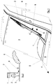
- the windscreen wiper consists of a wiper arm 1 and a wiper blade 2. It is on a windshield surface 3 between two positions by one axis not shown pivotable. In the first (resting) Position of the windshield wipers is partially behind a hood 4 near a lower window frame 5. In the second position, which is shown in FIG. 1 the wiper is close to a side Window frame 6 of the driver's side of the motor vehicle.
- the Wiper blade 2 has an approximately parallel to the window frame 6 Location.
- a guide element 7 is attached, which from there towards the windshield surface 3 up to close to this. It is in the direction of travel F behind or with an upward movement of the wiper arranged in front of this, approximately perpendicular to Windshield surface 3 aligned and influenced thus in particular the one just in front of the pane surface 3 Air flow.
- the wiper forms the guide element 7 together with the side window frame 6, an air duct 8 which the wiper blade 2 is excluded.
- An air flow in the air duct 8 cannot flow off via the wiper blade 2, but displaces what is behind the wiper blade 2 Water up. It no longer exists there - As in the prior art - a negative pressure zone, but a zone of increased air pressure so that from the wiper funded in the direction of the side window frame 6 Water drains off quickly and is not "dragged back" becomes.
- the rapid drainage of water is not only in the upper end position of the wiper by the action of the Air channel 8 promoted, but the guide element 7 has already positive influence during the upward movement of the wiper.
- the wind from the wiper blade 2 deflected from the disc surface 3, and behind the wiper blade consists of a vacuum zone from which Water drains poorly.
- the guide element 7 limits now a narrow gap 9 between itself and the windshield surface 3.
- the Wipers will wipe air over wiper blade 2, but then from the guide element 7 back to the disc surface 3 steered until it passes the gap 9. So there is thus also when the wiper is moving upwards a zone of increased pressure so that water immediately is displaced from this zone.
Landscapes
- Engineering & Computer Science (AREA)
- Mechanical Engineering (AREA)
- Physics & Mathematics (AREA)
- Fluid Mechanics (AREA)
- Quality & Reliability (AREA)
- Body Structure For Vehicles (AREA)
- Cleaning In General (AREA)
Abstract
Description
- Fig. 1:
- einen erfindungsgemäßen Scheibenwischer in einer nach oben verschwenkten Betriebsposition in perspektivischer Darstellungsweise,
- Fig. 2:
- Schnitt II-II aus Figur 1 in schematischer Darstellungsweise.
Claims (4)
- Scheibenwischer für die Windschutzscheibenfläche (3) eines Kraftfahrzeugs, der aus einem Wischerarm (1) und einem Wischerblatt (2) sowie aus Mitteln zur Beeinflussung der Luftströmung vor der Windschutzscheibenfläche (3) besteht, wobei der Scheibenwischer um eine Achse zwischen zwei Positionen verschwenkbar ist, wovon eine erste nahe eines unteren Scheibenrahmens (5) und eine zweite Position nahe eines seitlichen Scheibenrahmens (6) gelegen ist, dadurch gekennzeichnet, daß ein Mittel zur Beeinflussung der Luftströmung aus einem etwa senkrecht zur Windschutzscheibenfläche (3) ausgerichteten Leitelement (7) besteht, welches bis nahe an die Windschutzscheibenfläche (3) heranreicht und derart angeordnet ist, daß es in der zweiten Position des Scheibenwischers einen das Wischerblatt (2) ausgrenzenden Luftkanal (8) mit dem seitlichen Scheibenrahmen (6) bildet.
- Scheibenwischer nach Anspruch 1, dadurch gekennzeichnet, daß er für die Fahrerseite des Kraftfahrzeugs zum Einsatz kommt.
- Scheibenwischer nach Anspruch 1 und 2, dadurch gekennzeichnet, daß das Leitelement (7) am Wischerarm (1) befestigt ist und von diesem aus in Richtung der Windschutzscheibenfläche (3) weist.
- Scheibenwischer nach Anspruch 1 und 2, dadurch gekennzeichnet, daß das Leitelement (7) am Wischerblatt (2) befestigt ist.
Applications Claiming Priority (2)
| Application Number | Priority Date | Filing Date | Title |
|---|---|---|---|
| DE19633139 | 1996-08-16 | ||
| DE19633139A DE19633139A1 (de) | 1996-08-16 | 1996-08-16 | Scheibenwischer für die Windschutzscheibenfläche eines Kraftfahrzeugs |
Publications (2)
| Publication Number | Publication Date |
|---|---|
| EP0825075A1 true EP0825075A1 (de) | 1998-02-25 |
| EP0825075B1 EP0825075B1 (de) | 2001-11-07 |
Family
ID=7802849
Family Applications (1)
| Application Number | Title | Priority Date | Filing Date |
|---|---|---|---|
| EP97113540A Expired - Lifetime EP0825075B1 (de) | 1996-08-16 | 1997-08-06 | Scheibenwischer für die Windschutzscheibenfläche eines Kraftfahrzeugs |
Country Status (3)
| Country | Link |
|---|---|
| EP (1) | EP0825075B1 (de) |
| DE (2) | DE19633139A1 (de) |
| ES (1) | ES2167653T3 (de) |
Citations (4)
| Publication number | Priority date | Publication date | Assignee | Title |
|---|---|---|---|---|
| FR2556297A1 (fr) * | 1983-12-09 | 1985-06-14 | Champion Spark Plug Europ | Dispositif deflecteur d'air pour un systeme d'essuie-glace |
| GB2195076A (en) * | 1986-09-13 | 1988-03-30 | Nissan Motor | Wiper blade assembly having wind deflecting yoke |
| DE4405926A1 (de) * | 1994-02-24 | 1995-08-31 | Daimler Benz Ag | Fahrzeugscheibenwischer |
| DE19650924A1 (de) * | 1995-12-19 | 1997-06-26 | Volkswagen Ag | Strömungsoptimiertes Scheibenwischerblatt |
-
1996
- 1996-08-16 DE DE19633139A patent/DE19633139A1/de not_active Withdrawn
-
1997
- 1997-08-06 DE DE59705251T patent/DE59705251D1/de not_active Expired - Lifetime
- 1997-08-06 ES ES97113540T patent/ES2167653T3/es not_active Expired - Lifetime
- 1997-08-06 EP EP97113540A patent/EP0825075B1/de not_active Expired - Lifetime
Patent Citations (4)
| Publication number | Priority date | Publication date | Assignee | Title |
|---|---|---|---|---|
| FR2556297A1 (fr) * | 1983-12-09 | 1985-06-14 | Champion Spark Plug Europ | Dispositif deflecteur d'air pour un systeme d'essuie-glace |
| GB2195076A (en) * | 1986-09-13 | 1988-03-30 | Nissan Motor | Wiper blade assembly having wind deflecting yoke |
| DE4405926A1 (de) * | 1994-02-24 | 1995-08-31 | Daimler Benz Ag | Fahrzeugscheibenwischer |
| DE19650924A1 (de) * | 1995-12-19 | 1997-06-26 | Volkswagen Ag | Strömungsoptimiertes Scheibenwischerblatt |
Also Published As
| Publication number | Publication date |
|---|---|
| EP0825075B1 (de) | 2001-11-07 |
| ES2167653T3 (es) | 2002-05-16 |
| DE59705251D1 (de) | 2001-12-13 |
| DE19633139A1 (de) | 1998-02-19 |
Similar Documents
| Publication | Publication Date | Title |
|---|---|---|
| EP0633170B1 (de) | Wischblatt für Scheiben von Kraftfahrzeugen | |
| DE3139445C2 (de) | ||
| DE3119702A1 (de) | Scheibenwischer | |
| DE69802823T2 (de) | Wischblatt mit einem windleitelement | |
| DE3424729C2 (de) | ||
| DE10343938B4 (de) | Wischarm | |
| DE10139104A1 (de) | Wischblatt, insbesondere Flachwischblatt | |
| DE2705700A1 (de) | Vorrichtung zum saeubern der sichtscheiben von kraftfahrzeugen oder flugzeugen | |
| DE2838451C3 (de) | Vorrichtung zum Verhindern des Abhebens von Scheibenwischerblättern infolge Fahrtwind bei Kraftfahrzeugen | |
| DE3532535C2 (de) | Scheibenwischer, insbesondere für Scheibenwischanlagen von Kraftfahrzeugen | |
| DE19901818B4 (de) | Wischerblatt | |
| EP3096987B1 (de) | Wischeinrichtung und verfahren zum wischen | |
| DE10058455B4 (de) | Wischeranordnung und Verfahren zum Betreiben einer Wischeranordnung | |
| DE2409680C3 (de) | Einrichtung zum Reinigen der Glasscheiben von Fahrzeugen | |
| EP0952018A2 (de) | Vorrichtung zum Verhindern eines Kontaktes von Schmutzwasser mit einem Seitenfenster eines Fahrzeuges | |
| EP0825075B1 (de) | Scheibenwischer für die Windschutzscheibenfläche eines Kraftfahrzeugs | |
| DE102004012867B4 (de) | Scheibenwischer für die Scheibenwischeranlage an einem Fahrzeug | |
| EP0499829A1 (de) | Wischvorrichtung für Scheiben von Kraftfahrzeugen | |
| EP1037777B1 (de) | Wischarm | |
| WO1997047488A1 (de) | Belüftungsdüse für kraftfahrzeuge | |
| DE19854372A1 (de) | Wischblatt zum Reinigen einer Fahrzeugscheibe | |
| DE10130381A1 (de) | Wischerarm, Wischblatt und Wischvorrichtung, insbesondere für Scheiben von Kraftfahrzeugen | |
| DE3923947A1 (de) | Aussenspiegel fuer kraftfahrzeuge | |
| DE69202188T2 (de) | Lamellenluftleitblech, insbesondere für Kraftfahrzeuge. | |
| DE102017207108B4 (de) | Spoilervorrichtung |
Legal Events
| Date | Code | Title | Description |
|---|---|---|---|
| PUAI | Public reference made under article 153(3) epc to a published international application that has entered the european phase |
Free format text: ORIGINAL CODE: 0009012 |
|
| AK | Designated contracting states |
Kind code of ref document: A1 Designated state(s): DE ES FR GB IT |
|
| AX | Request for extension of the european patent |
Free format text: AL;LT;LV;RO;SI |
|
| 17P | Request for examination filed |
Effective date: 19980805 |
|
| AKX | Designation fees paid |
Free format text: DE ES FR GB IT |
|
| RBV | Designated contracting states (corrected) |
Designated state(s): DE ES FR GB IT |
|
| 17Q | First examination report despatched |
Effective date: 19991126 |
|
| GRAG | Despatch of communication of intention to grant |
Free format text: ORIGINAL CODE: EPIDOS AGRA |
|
| GRAG | Despatch of communication of intention to grant |
Free format text: ORIGINAL CODE: EPIDOS AGRA |
|
| GRAH | Despatch of communication of intention to grant a patent |
Free format text: ORIGINAL CODE: EPIDOS IGRA |
|
| GRAH | Despatch of communication of intention to grant a patent |
Free format text: ORIGINAL CODE: EPIDOS IGRA |
|
| ITF | It: translation for a ep patent filed | ||
| GRAA | (expected) grant |
Free format text: ORIGINAL CODE: 0009210 |
|
| AK | Designated contracting states |
Kind code of ref document: B1 Designated state(s): DE ES FR GB IT |
|
| REF | Corresponds to: |
Ref document number: 59705251 Country of ref document: DE Date of ref document: 20011213 |
|
| REG | Reference to a national code |
Ref country code: GB Ref legal event code: IF02 |
|
| ET | Fr: translation filed | ||
| GBT | Gb: translation of ep patent filed (gb section 77(6)(a)/1977) |
Effective date: 20020110 |
|
| REG | Reference to a national code |
Ref country code: ES Ref legal event code: FG2A Ref document number: 2167653 Country of ref document: ES Kind code of ref document: T3 |
|
| PLBE | No opposition filed within time limit |
Free format text: ORIGINAL CODE: 0009261 |
|
| STAA | Information on the status of an ep patent application or granted ep patent |
Free format text: STATUS: NO OPPOSITION FILED WITHIN TIME LIMIT |
|
| 26N | No opposition filed | ||
| REG | Reference to a national code |
Ref country code: GB Ref legal event code: 732E Free format text: REGISTERED BETWEEN 20090219 AND 20090225 |
|
| REG | Reference to a national code |
Ref country code: GB Ref legal event code: 732E Free format text: REGISTERED BETWEEN 20090305 AND 20090311 |
|
| REG | Reference to a national code |
Ref country code: GB Ref legal event code: 732E Free format text: REGISTERED BETWEEN 20091029 AND 20091104 |
|
| REG | Reference to a national code |
Ref country code: GB Ref legal event code: 732E Free format text: REGISTERED BETWEEN 20091105 AND 20091111 |
|
| REG | Reference to a national code |
Ref country code: DE Ref legal event code: R081 Ref document number: 59705251 Country of ref document: DE Owner name: GM GLOBAL TECHNOLOGY OPERATIONS LLC (N. D. GES, US Free format text: FORMER OWNER: GM GLOBAL TECHNOLOGY OPERATIONS, INC., DETROIT, MICH., US Effective date: 20110323 Ref country code: DE Ref legal event code: R081 Ref document number: 59705251 Country of ref document: DE Owner name: GM GLOBAL TECHNOLOGY OPERATIONS LLC (N. D. GES, US Free format text: FORMER OWNER: GM GLOBAL TECHNOLOGY OPERATIONS, INC., DETROIT, US Effective date: 20110323 |
|
| PGFP | Annual fee paid to national office [announced via postgrant information from national office to epo] |
Ref country code: GB Payment date: 20120801 Year of fee payment: 16 |
|
| PGFP | Annual fee paid to national office [announced via postgrant information from national office to epo] |
Ref country code: ES Payment date: 20120907 Year of fee payment: 16 Ref country code: FR Payment date: 20120823 Year of fee payment: 16 Ref country code: DE Payment date: 20120731 Year of fee payment: 16 Ref country code: IT Payment date: 20120811 Year of fee payment: 16 |
|
| GBPC | Gb: european patent ceased through non-payment of renewal fee |
Effective date: 20130806 |
|
| PG25 | Lapsed in a contracting state [announced via postgrant information from national office to epo] |
Ref country code: DE Free format text: LAPSE BECAUSE OF NON-PAYMENT OF DUE FEES Effective date: 20140301 |
|
| REG | Reference to a national code |
Ref country code: DE Ref legal event code: R119 Ref document number: 59705251 Country of ref document: DE Effective date: 20140301 |
|
| REG | Reference to a national code |
Ref country code: FR Ref legal event code: ST Effective date: 20140430 |
|
| PG25 | Lapsed in a contracting state [announced via postgrant information from national office to epo] |
Ref country code: IT Free format text: LAPSE BECAUSE OF NON-PAYMENT OF DUE FEES Effective date: 20130806 |
|
| PG25 | Lapsed in a contracting state [announced via postgrant information from national office to epo] |
Ref country code: GB Free format text: LAPSE BECAUSE OF NON-PAYMENT OF DUE FEES Effective date: 20130806 |
|
| PG25 | Lapsed in a contracting state [announced via postgrant information from national office to epo] |
Ref country code: FR Free format text: LAPSE BECAUSE OF NON-PAYMENT OF DUE FEES Effective date: 20130902 |
|
| REG | Reference to a national code |
Ref country code: ES Ref legal event code: FD2A Effective date: 20140909 |
|
| PG25 | Lapsed in a contracting state [announced via postgrant information from national office to epo] |
Ref country code: ES Free format text: LAPSE BECAUSE OF NON-PAYMENT OF DUE FEES Effective date: 20130807 |