EP0825307B1 - Concrete wing floor element - Google Patents
Concrete wing floor element Download PDFInfo
- Publication number
- EP0825307B1 EP0825307B1 EP97202572A EP97202572A EP0825307B1 EP 0825307 B1 EP0825307 B1 EP 0825307B1 EP 97202572 A EP97202572 A EP 97202572A EP 97202572 A EP97202572 A EP 97202572A EP 0825307 B1 EP0825307 B1 EP 0825307B1
- Authority
- EP
- European Patent Office
- Prior art keywords
- shaped part
- floor
- wing
- wings
- floor element
- Prior art date
- Legal status (The legal status is an assumption and is not a legal conclusion. Google has not performed a legal analysis and makes no representation as to the accuracy of the status listed.)
- Expired - Lifetime
Links
- 230000003014 reinforcing effect Effects 0.000 claims abstract description 21
- 230000002787 reinforcement Effects 0.000 claims abstract description 15
- 238000011065 in-situ storage Methods 0.000 description 6
- 238000009416 shuttering Methods 0.000 description 6
- 238000000034 method Methods 0.000 description 5
- 238000004519 manufacturing process Methods 0.000 description 4
- 238000010276 construction Methods 0.000 description 3
- 238000000465 moulding Methods 0.000 description 3
- 230000000284 resting effect Effects 0.000 description 2
- 238000006073 displacement reaction Methods 0.000 description 1
- 235000000396 iron Nutrition 0.000 description 1
- 239000000463 material Substances 0.000 description 1
- 238000010008 shearing Methods 0.000 description 1
Images


Classifications
-
- E—FIXED CONSTRUCTIONS
- E04—BUILDING
- E04B—GENERAL BUILDING CONSTRUCTIONS; WALLS, e.g. PARTITIONS; ROOFS; FLOORS; CEILINGS; INSULATION OR OTHER PROTECTION OF BUILDINGS
- E04B5/00—Floors; Floor construction with regard to insulation; Connections specially adapted therefor
- E04B5/02—Load-carrying floor structures formed substantially of prefabricated units
- E04B5/04—Load-carrying floor structures formed substantially of prefabricated units with beams or slabs of concrete or other stone-like material, e.g. asbestos cement
- E04B5/043—Load-carrying floor structures formed substantially of prefabricated units with beams or slabs of concrete or other stone-like material, e.g. asbestos cement having elongated hollow cores
-
- E—FIXED CONSTRUCTIONS
- E04—BUILDING
- E04B—GENERAL BUILDING CONSTRUCTIONS; WALLS, e.g. PARTITIONS; ROOFS; FLOORS; CEILINGS; INSULATION OR OTHER PROTECTION OF BUILDINGS
- E04B5/00—Floors; Floor construction with regard to insulation; Connections specially adapted therefor
- E04B5/16—Load-carrying floor structures wholly or partly cast or similarly formed in situ
- E04B5/17—Floor structures partly formed in situ
- E04B5/23—Floor structures partly formed in situ with stiffening ribs or other beam-like formations wholly or partly prefabricated
-
- E—FIXED CONSTRUCTIONS
- E04—BUILDING
- E04B—GENERAL BUILDING CONSTRUCTIONS; WALLS, e.g. PARTITIONS; ROOFS; FLOORS; CEILINGS; INSULATION OR OTHER PROTECTION OF BUILDINGS
- E04B5/00—Floors; Floor construction with regard to insulation; Connections specially adapted therefor
- E04B5/16—Load-carrying floor structures wholly or partly cast or similarly formed in situ
- E04B5/32—Floor structures wholly cast in situ with or without form units or reinforcements
- E04B5/36—Floor structures wholly cast in situ with or without form units or reinforcements with form units as part of the floor
- E04B5/38—Floor structures wholly cast in situ with or without form units or reinforcements with form units as part of the floor with slab-shaped form units acting simultaneously as reinforcement; Form slabs with reinforcements extending laterally outside the element
Definitions
- the invention relates to a prefabricated concrete floor element, at least consisting of a cantilever beam-shaped part, provided with longitudinally extending, hollow cores and reinforcing wires parallel thereto.
- Such floor elements are known from practice by the name of "hollow-core slab floors” and are for instance shown in Fig. 1B of EP-B-0.634.966.
- the maximum width of these hollow floor slabs is 1200 mm, because a greater width requires the provision of transverse reinforcement, which is problematic in the production techniques that are hitherto known.
- This floor element consists of a relatively thin floor slab having longitudinal and transverse reinforcement as well as reinforcement elements protruding from the top face, which can be embedded in concrete to form ribs.
- These floor elements are provided as a shuttering floor, on which, subsequently, a layer of concrete is poured.
- the shuttering floor should be propped up.
- the entire floor has no seams and therefore remains flat, while pipes can be concealed in the floor.
- the propping-up operations slow down the building process and the thus composed floor is only passable and capable of carrying a load after the concrete poured in situ has sufficiently hardened.
- the weight of the floor, compared with hollow core slab floors is relatively high.
- a third type of floor is known from BE-A-404950 and FR-A-2660952 and composed of relatively narrow, winged, hollow core beams.
- Pipes can be placed beneath the floor surface by situating the pipes above the wings adjacent the beam part. Width adjustment is relatively easy by the small width of the winged beams, but the large number of beams to be placed as well as the large number of channels to be filled with concrete slows the fitting speed. Due to the narrow beams the floor is difficult passable after filling the channels with concrete.
- the wings have to be short to maintain a sufficient strength for the floor.
- Object of the invention is providing a prefabricated floor element which overcomes the drawbacks of the three types of above-mentioned floor elements and combines the advantages thereof. According to the invention this object is realized by a prefabricated concrete floor element for constructing a floor field with a predetermined thickness, and comprising:
- the floor elements When a floor built up from prefabricated floor elements is being provided, the floor elements are laid with the lateral edges of the wings against one another. Consequently, a channel is formed above these wings, in which channel all types of pipes can be fitted, after which this space is filled up in situ with concrete. Unlike adjoining hollow core slabs, the top face of the concrete can properly connect to the top faces of the adjoining beam-shaped parts of the floor elements.
- the transverse reinforcement not present in the above discussed hollow-core floor slabs for the reason specified, is in fact provided in the floor elements according to the invention, because the method for the manufacture thereof has been divided into two steps. During the first molding operation, a continuous layer is formed with the thickness of the wings, in which layer a reinforcement can be provided, while subsequently, in a second step, the top layer of the beam-shaped part is provided on the bottom layer formed in the first step.
- FR-A-2 660 952 discloses a prefabricated concrete floor element consisting of a cantilever, beam-shaped part, provided with a longitudinally extending hollow core, which beam-shaped part is on either side provided with laterally projecting wings.
- This floor element is manufactured by means of a continuous molding process, so that transverse reinforcement is lacking. Hence, the wings have a slight width.
- DE-C-816 598 teaches a built-up floor consisting of a relatively thin shuttering floor slab stiffened by means of lattice girders provided on this floor slab.
- the floor slab must be propped up. Inserted between the lattice girders are loose, hollow shuttering beams, over which, next, concrete is poured.
- DE-A-29 46589 discloses a prefabricated concrete floor element consisting of a cantilever beam-shaped part comprising at least one longitudinally extending hollow core and reinforcing wires parallel thereto or reinforcement grids at the location of the dams of the beam-shaped part.
- This part has its bottom side provided with laterally projecting wings in which longitudinal as well as transverse reinforcing wires are present, which transverse reinforcing wires continue into the bottom layer of the beam-shaped part.
- the hollow cores are partly filled with synthetic displacement bodies serving as shuttering mold during the production of the beam-shaped part.
- the top layer of the beam-shaped part is formed by a concrete slab that is likewise provided with longitudinal and transverse reinforcement, of which the transverse reinforcing bars project laterally from the beam-shaped part over a length that is approximately equal to the width of the wing.
- the open space above this wing is at the top side bounded by a grid of reinforcing bars, which seriously complicates the provision of pipes in that space to be filled up later on.
- the width of the wings is slight relative to the width of the beam-shaped part.
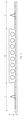
- the wing floor element 1, as shown in Fig. 1, consists of centrally located beam-shaped part 2 having wings 3 formed thereon on either side thereof.
- the width B of the beam-shaped part is for instance 600 mm, while the width b of the wings is 300 mm.
- Provided in the beam-shaped part 2 are four hollow cores 4 for saving material and weight.
- longitudinal reinforcing wires 5 are provided, parallel to the hollow cores 4.
- the bottom face 11 of the wings 3 aligns with the bottom face of the beam-shaped part 2.
- the thickness D of the beam-shaped part can for instance be 180-200 mm and the wing thickness d is 50-70 mm.
- the thickness dimensions D and d depend on the desired degree of fire resistance of the floor element 1, or other requirements in terms of building physics and construction.
- a layer of concrete is formed having the width of the wing floor element 1 at the location of the wings 3.
- a longitudinal reinforcement 6 as well as a transverse reinforcement 7 is provided.
- the top layer 9 of the beam-shaped part 2 is formed on the top face 12 of this first layer. Projecting from the top face 12 of the wings 3 are reinforcing elements 10 for supporting additional reinforcement and taking up possible shearing forces in the concrete to be poured in situ for filling up the space bounded by two abutting wings 3 of adjacent wing floor elements 1 and the upwardly directed lateral sides of the beam-shaped parts 2 of those wing floor elements 1.
- the wing floor element as shown in Fig. 2 differs from the wing floor element according to Fig. 1 in that the width B of the beam-shaped part 2 as well as the width b of the wings 3 has been increased by a factor 2. Accordingly, the number of longitudinally extending hollow cores 4 in the beam-shaped part 2 has been doubled.
- the width b of the wings can readily be adjusted and this width may also be zero, so that only one laterally projecting wing is formed on the beam-shaped part 2. It is also possible to provide the wings 3 with a certain incline in longitudinal direction, if so desired.
- the length of the wing floor element 1 can be chosen arbitrarily. In principle, the lengths of the beam-shaped part 2 and the wings 3 will be equal. An inclined end face is possible.
- the top layer 9 of the beam-shaped part 2 can be given a shorter length than the wings, as shown in Fig. 3, in which the wings project in longitudinal direction over a distance R from the end of the beam-shaped part 2, at least on one side thereof.
- This length difference R is extremely useful with wing floor elements that are used at the location of a hole in the floor, for instance a stairwell, in that this provides the possibility of providing a transversely extending reinforcement that can be incorporated into the concrete to be poured in situ.
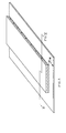
- Fig. 4 shows, by way of example, a floor field 20 built up from wing floor elements, of which floor field the dimensions are 8300 x 5330 mm. In the floor, an opening is made for a stairwell 26 whose dimensions are 2060 x 1050 mm.
- the floor 20 is built up from five wing floor elements 22-25 having their end edges resting on a circumferential supporting edge 21 of a supporting construction, for instance formed by walls.
- the outermost floor elements 22 have their longitudinal sides resting on this edge 21 as well.
- the two floor elements 22 have a beam-shaped part having a width B of 600 mm, to which one single lateral wing connects having a width of 130 mm.
- the floor element 23 connecting thereto has a beam-shaped part having a width of 1200 mm, on which, on either side, wings having a width of 600 mm are provided.
- the floor element 24 has a beam-shaped part which also has a width of 1200 mm and wings of a width of 600 mm provided on either side thereof.
- the wings and the bottom layer 8 of the beam-shaped part continue to the stairwell, the top part 9 of the beam-shaped element ends at a certain distance from the end edge of the wings.
- the floor element 24 is of the type as shown in Fig. 3.
- the floor element 25 Connecting to the floor element 24, the floor element 25 is provided, of which the width of the beam-shaped part 2 is likewise 1200 mm, on either side provided with wings having a width of 420 mm. Hence, all beam-shaped parts of the floor elements 22-25 have a width of 600 or 1200 mm.
- the wing width of the floor elements 22 and 25 is adapted to the design depth of the floor and the location of the stairwell 26.
- One end of the floor element 24 finds no support on the circumferential edge 21 and should therefore be temporarily supported in a different manner, for instance by the possibly supported shuttering of the stairwell 26 to be shuttered in situ.
- the reinforcing elements 27 are provided to obtain a firm support of the end of the floor element 24 by the adjacent floor elements 23 and 25.
- the reinforcing elements 27 may have the shape of so-called concealed consoles or of a continuous trimmer strip.
- the hatched regions in Fig. 4 indicate the concrete poured in situ.
- the dashed lines present in those hatched regions indicate where adjoining floor elements have their wing edges abutting against one another.
- Fig. 5 shows a floor element which does not only have longitudinally extending hollow cores 4, but also transversely extending hollow cores 4'. These transverse hollow cores 4' facilitate the provision of continuous pipes on either side of the beam-shaped part 2 of the floor element.
Landscapes
- Engineering & Computer Science (AREA)
- Architecture (AREA)
- Physics & Mathematics (AREA)
- Electromagnetism (AREA)
- Civil Engineering (AREA)
- Structural Engineering (AREA)
- On-Site Construction Work That Accompanies The Preparation And Application Of Concrete (AREA)
- Vehicle Interior And Exterior Ornaments, Soundproofing, And Insulation (AREA)
- Joining Of Building Structures In Genera (AREA)
- Building Environments (AREA)
- Floor Finish (AREA)
- Forms Removed On Construction Sites Or Auxiliary Members Thereof (AREA)
- Curing Cements, Concrete, And Artificial Stone (AREA)
- Rod-Shaped Construction Members (AREA)
- Panels For Use In Building Construction (AREA)
Applications Claiming Priority (2)
| Application Number | Priority Date | Filing Date | Title |
|---|---|---|---|
| NL1003858A NL1003858C2 (nl) | 1996-08-22 | 1996-08-22 | Vleugelvloerelement van beton. |
| NL1003858 | 1996-08-22 |
Publications (2)
| Publication Number | Publication Date |
|---|---|
| EP0825307A1 EP0825307A1 (en) | 1998-02-25 |
| EP0825307B1 true EP0825307B1 (en) | 2001-05-23 |
Family
ID=19763405
Family Applications (1)
| Application Number | Title | Priority Date | Filing Date |
|---|---|---|---|
| EP97202572A Expired - Lifetime EP0825307B1 (en) | 1996-08-22 | 1997-08-21 | Concrete wing floor element |
Country Status (5)
| Country | Link |
|---|---|
| EP (1) | EP0825307B1 (da) |
| AT (1) | ATE201472T1 (da) |
| DE (1) | DE69704911T2 (da) |
| DK (1) | DK0825307T3 (da) |
| NL (1) | NL1003858C2 (da) |
Families Citing this family (14)
| Publication number | Priority date | Publication date | Assignee | Title |
|---|---|---|---|---|
| NL1013136C2 (nl) * | 1999-09-24 | 2000-07-31 | Vbi Ontwikkeling Bv | Kanaalplaat voor het vormen van een vloerveld waarin leidingen kunnen worden opgenomen, alsmede werkwijze voor het vormen van een vloerveld met leidingen met behulp van dergelijke kanaalplaten. |
| FR2812310B1 (fr) * | 2000-07-25 | 2003-10-10 | Composants Precontraints | Longeron de pont prefabrique et procede de fabrication d'un tel pont |
| CN1112491C (zh) * | 2001-11-23 | 2003-06-25 | 邱则有 | 一种钢筋砼空间结构楼板用模壳结构构件 |
| NL1020183C2 (nl) | 2002-03-15 | 2003-09-16 | Beton Son Bv | Werkwijze voor het aanbrengen van een hijshaak in een geprefabriceerd betonelement zoals een kanaalplaatvloer. |
| FR2851780B1 (fr) * | 2003-02-27 | 2006-05-19 | Longeron prefabrique de pont, ensemble de positionnement relatif de deux longerons et moyen de liaison de feux longerons | |
| ITMI20120730A1 (it) * | 2012-05-02 | 2013-11-03 | Luscari Salvatore Lembo | Nuovo blocco o pannello auto-portante, a struttura alleggerita, in particolare per la realizzazione di solai in cemento armato da gettare in opera |
| FR3002960B1 (fr) * | 2013-03-11 | 2015-08-07 | Ligerienne Beton | Ensemble de longeron a armature coulissante |
| CN103410265A (zh) * | 2013-08-07 | 2013-11-27 | 南京工业大学 | 一种叠合楼板的拼接构造 |
| EP2955294A1 (de) * | 2014-06-13 | 2015-12-16 | Elbe Spannbetonwerk GmbH & Co. KG | Spannbetonhohlplatte |
| CN104712080A (zh) * | 2015-01-17 | 2015-06-17 | 安徽建筑大学 | 一种由钢板作拼缝拼接的叠合墙板 |
| CN105507470B (zh) * | 2015-12-31 | 2018-03-16 | 中南大学 | 一种周边叠合整体装配式楼板及其施工方法 |
| CN108343184A (zh) * | 2018-02-02 | 2018-07-31 | 广州市第二市政工程有限公司 | 企口空心预制板和井字现浇梁相结合的楼板施工方法 |
| FI129460B (en) | 2019-02-12 | 2022-02-28 | Elematic Oyj | Method for manufacturing prefabricated concrete products |
| CN110056111A (zh) * | 2019-04-18 | 2019-07-26 | 江苏广兴集团建筑装配科技有限公司 | 一种连接稳定的叠合板 |
Family Cites Families (8)
| Publication number | Priority date | Publication date | Assignee | Title |
|---|---|---|---|---|
| BE404950A (da) * | ||||
| DE816598C (de) * | 1950-06-27 | 1951-10-11 | Paul Bode | Montagebauweise fuer Betonhaeuser |
| DE2946589A1 (de) * | 1979-11-19 | 1981-05-21 | Karl 8551 Heiligenstadt Schmidt | Decke aus bspw. 2,20 m breiten elementen, die im zuge der deckenverlegung nebeneinanderlegbar und an den stossfugen vergiessbar sind |
| FR2542784B1 (fr) * | 1983-03-18 | 1987-11-27 | Etre Ste Civile Particuliere | Dispositif d'element de construction arme et en forme de plaque pour la construction |
| AT375992B (de) * | 1983-03-28 | 1984-09-25 | Katzenberger Helmut | Stahlbetondecke |
| FR2660952B1 (fr) * | 1990-04-17 | 1993-09-03 | Ibse | Elements prefabriques pour la realisation d'une dalle et dalle obtenue a partir de ces elements. |
| GB2249329B (en) * | 1990-11-02 | 1995-05-24 | Mohammad Hossein Shamsai | Beam/flooring system |
| DE4315254A1 (de) * | 1993-05-07 | 1994-11-10 | Filigran Traegersysteme | Verfahren zum Herstellen eines Deckenelements |
-
1996
- 1996-08-22 NL NL1003858A patent/NL1003858C2/nl not_active IP Right Cessation
-
1997
- 1997-08-21 DE DE69704911T patent/DE69704911T2/de not_active Expired - Lifetime
- 1997-08-21 AT AT97202572T patent/ATE201472T1/de not_active IP Right Cessation
- 1997-08-21 DK DK97202572T patent/DK0825307T3/da active
- 1997-08-21 EP EP97202572A patent/EP0825307B1/en not_active Expired - Lifetime
Also Published As
| Publication number | Publication date |
|---|---|
| NL1003858C2 (nl) | 1998-02-26 |
| DE69704911T2 (de) | 2002-04-04 |
| ATE201472T1 (de) | 2001-06-15 |
| DE69704911D1 (de) | 2001-06-28 |
| EP0825307A1 (en) | 1998-02-25 |
| DK0825307T3 (da) | 2001-09-10 |
Similar Documents
| Publication | Publication Date | Title |
|---|---|---|
| EP0825307B1 (en) | Concrete wing floor element | |
| US9988775B1 (en) | Concrete i-beam for bridge construction | |
| US7121061B2 (en) | Reinforced concrete building system | |
| EP1325991B1 (en) | Method for manufacturing a floor of concrete and shuttering slab for use therein | |
| GB2361254A (en) | Interlocking mortarless building block system | |
| EP0289261A2 (en) | Concrete screed rails | |
| KR102171006B1 (ko) | 강화 콘크리트 바닥을 구축하기 위한 소결 발포 폴리스티렌 모듈형 요소 | |
| PL213385B1 (pl) | Uklad rozdzielania cieplnego dla stropu z betonu zawierajacego plyte z betonu deskowana na konstrukcji z belek i wypelnien stropowych oraz strop z betonu zawierajacy plyte z betonu deskowana na konstrukcji z belek i wypelnien stropowych | |
| EP0345823B1 (en) | Screed rails | |
| GB2355024A (en) | Insulating building panel of polystyrene and concrete | |
| US3949531A (en) | Hollow cored concrete slab and method of making the same | |
| AT391731B (de) | Deckenplatte und verfahren zu ihrer herstellung sowie anordnung zur durchfuehrung des verfahrens | |
| US4912896A (en) | Beam/flooring system | |
| EP0016478A2 (en) | Wall made of a plurality of pre cast cementitious panels | |
| WO2001000943A1 (en) | Hollow filler block for a block-and-rib reinforced concrete slab | |
| KR101677233B1 (ko) | 천정 벽돌과 이를 적용한 건축물의 천정 구조물 및 그 시공 방법 | |
| GB2249329A (en) | Concrete floor beams | |
| US6442910B1 (en) | Composite building system | |
| US7073300B1 (en) | Reinforced concrete part for producing foundations of buildings | |
| JP3619301B2 (ja) | 擁壁用基礎ブロック | |
| EP1103663B1 (en) | Pile wall capping | |
| NL1013055C2 (nl) | Industrieel prefabriceerbaar, modulair vloerplaatelement voor gebouwen, in het bijzonder voor woningen. | |
| NL1006527C2 (nl) | Werkwijze voor het vervaardigen van een fundering en bij deze werkwijze toepasbare betonplaat. | |
| EP1120505B1 (en) | A building block suitable for the construction of dry-stacking high performance masonry walls | |
| US2087522A (en) | Gypsum timber |
Legal Events
| Date | Code | Title | Description |
|---|---|---|---|
| PUAI | Public reference made under article 153(3) epc to a published international application that has entered the european phase |
Free format text: ORIGINAL CODE: 0009012 |
|
| AK | Designated contracting states |
Kind code of ref document: A1 Designated state(s): AT BE CH DE DK FI FR GB LI LU NL SE |
|
| AX | Request for extension of the european patent |
Free format text: AL;LT;LV;RO;SI |
|
| 17P | Request for examination filed |
Effective date: 19980817 |
|
| AKX | Designation fees paid |
Free format text: AT BE CH DE DK FI FR GB LI LU NL SE |
|
| AXX | Extension fees paid |
Free format text: LT PAYMENT 980817;LV PAYMENT 980817 |
|
| RBV | Designated contracting states (corrected) |
Designated state(s): AT BE CH DE DK FI FR GB LI LU NL SE |
|
| 17Q | First examination report despatched |
Effective date: 19981207 |
|
| GRAG | Despatch of communication of intention to grant |
Free format text: ORIGINAL CODE: EPIDOS AGRA |
|
| GRAG | Despatch of communication of intention to grant |
Free format text: ORIGINAL CODE: EPIDOS AGRA |
|
| GRAH | Despatch of communication of intention to grant a patent |
Free format text: ORIGINAL CODE: EPIDOS IGRA |
|
| GRAH | Despatch of communication of intention to grant a patent |
Free format text: ORIGINAL CODE: EPIDOS IGRA |
|
| GRAA | (expected) grant |
Free format text: ORIGINAL CODE: 0009210 |
|
| AK | Designated contracting states |
Kind code of ref document: B1 Designated state(s): AT BE CH DE DK FI FR GB LI LU NL SE |
|
| AX | Request for extension of the european patent |
Free format text: LT PAYMENT 19980817;LV PAYMENT 19980817 |
|
| LTIE | Lt: invalidation of european patent or patent extension | ||
| REF | Corresponds to: |
Ref document number: 201472 Country of ref document: AT Date of ref document: 20010615 Kind code of ref document: T |
|
| REG | Reference to a national code |
Ref country code: CH Ref legal event code: EP |
|
| REF | Corresponds to: |
Ref document number: 69704911 Country of ref document: DE Date of ref document: 20010628 |
|
| ET | Fr: translation filed | ||
| REG | Reference to a national code |
Ref country code: DK Ref legal event code: T3 |
|
| REG | Reference to a national code |
Ref country code: CH Ref legal event code: NV Representative=s name: KIRKER & CIE SA |
|
| REG | Reference to a national code |
Ref country code: GB Ref legal event code: IF02 |
|
| PLBE | No opposition filed within time limit |
Free format text: ORIGINAL CODE: 0009261 |
|
| STAA | Information on the status of an ep patent application or granted ep patent |
Free format text: STATUS: NO OPPOSITION FILED WITHIN TIME LIMIT |
|
| 26N | No opposition filed | ||
| PGFP | Annual fee paid to national office [announced via postgrant information from national office to epo] |
Ref country code: LU Payment date: 20080624 Year of fee payment: 12 |
|
| PGFP | Annual fee paid to national office [announced via postgrant information from national office to epo] |
Ref country code: DK Payment date: 20080815 Year of fee payment: 12 Ref country code: CH Payment date: 20080826 Year of fee payment: 12 |
|
| PGFP | Annual fee paid to national office [announced via postgrant information from national office to epo] |
Ref country code: FR Payment date: 20080828 Year of fee payment: 12 Ref country code: FI Payment date: 20080711 Year of fee payment: 12 Ref country code: AT Payment date: 20080805 Year of fee payment: 12 |
|
| PGFP | Annual fee paid to national office [announced via postgrant information from national office to epo] |
Ref country code: SE Payment date: 20080814 Year of fee payment: 12 |
|
| REG | Reference to a national code |
Ref country code: CH Ref legal event code: PL |
|
| REG | Reference to a national code |
Ref country code: DK Ref legal event code: EBP |
|
| PG25 | Lapsed in a contracting state [announced via postgrant information from national office to epo] |
Ref country code: LI Free format text: LAPSE BECAUSE OF NON-PAYMENT OF DUE FEES Effective date: 20090831 Ref country code: FI Free format text: LAPSE BECAUSE OF NON-PAYMENT OF DUE FEES Effective date: 20090821 Ref country code: CH Free format text: LAPSE BECAUSE OF NON-PAYMENT OF DUE FEES Effective date: 20090831 |
|
| REG | Reference to a national code |
Ref country code: FR Ref legal event code: ST Effective date: 20100430 |
|
| PG25 | Lapsed in a contracting state [announced via postgrant information from national office to epo] |
Ref country code: AT Free format text: LAPSE BECAUSE OF NON-PAYMENT OF DUE FEES Effective date: 20090821 |
|
| PG25 | Lapsed in a contracting state [announced via postgrant information from national office to epo] |
Ref country code: FR Free format text: LAPSE BECAUSE OF NON-PAYMENT OF DUE FEES Effective date: 20090831 Ref country code: DK Free format text: LAPSE BECAUSE OF NON-PAYMENT OF DUE FEES Effective date: 20090831 |
|
| PG25 | Lapsed in a contracting state [announced via postgrant information from national office to epo] |
Ref country code: LU Free format text: LAPSE BECAUSE OF NON-PAYMENT OF DUE FEES Effective date: 20090821 |
|
| PG25 | Lapsed in a contracting state [announced via postgrant information from national office to epo] |
Ref country code: SE Free format text: LAPSE BECAUSE OF NON-PAYMENT OF DUE FEES Effective date: 20090822 |
|
| REG | Reference to a national code |
Ref country code: DE Ref legal event code: R082 Ref document number: 69704911 Country of ref document: DE Representative=s name: ARNOLD & SIEDSMA, DE |
|
| REG | Reference to a national code |
Ref country code: GB Ref legal event code: 732E Free format text: REGISTERED BETWEEN 20150305 AND 20150311 |
|
| REG | Reference to a national code |
Ref country code: DE Ref legal event code: R082 Ref document number: 69704911 Country of ref document: DE Representative=s name: ARNOLD & SIEDSMA, DE Effective date: 20150312 Ref country code: DE Ref legal event code: R082 Ref document number: 69704911 Country of ref document: DE Representative=s name: ARNOLD & SIEDSMA, DE Effective date: 20150414 Ref country code: DE Ref legal event code: R081 Ref document number: 69704911 Country of ref document: DE Owner name: BETONSON PREFAB B.V., NL Free format text: FORMER OWNER: BETONSON PREFAB B.V., DA GOUDA, NL Effective date: 20150414 Ref country code: DE Ref legal event code: R081 Ref document number: 69704911 Country of ref document: DE Owner name: BETONSON PREFAB B.V., NL Free format text: FORMER OWNER: BETON SON B.V., SON, NL Effective date: 20150312 |
|
| REG | Reference to a national code |
Ref country code: NL Ref legal event code: SD Effective date: 20150526 |
|
| PGFP | Annual fee paid to national office [announced via postgrant information from national office to epo] |
Ref country code: NL Payment date: 20160826 Year of fee payment: 20 |
|
| PGFP | Annual fee paid to national office [announced via postgrant information from national office to epo] |
Ref country code: GB Payment date: 20160830 Year of fee payment: 20 Ref country code: DE Payment date: 20160826 Year of fee payment: 20 |
|
| PGFP | Annual fee paid to national office [announced via postgrant information from national office to epo] |
Ref country code: BE Payment date: 20160829 Year of fee payment: 20 |
|
| REG | Reference to a national code |
Ref country code: DE Ref legal event code: R071 Ref document number: 69704911 Country of ref document: DE |
|
| REG | Reference to a national code |
Ref country code: NL Ref legal event code: MK Effective date: 20170820 |
|
| REG | Reference to a national code |
Ref country code: GB Ref legal event code: PE20 Expiry date: 20170820 |
|
| PG25 | Lapsed in a contracting state [announced via postgrant information from national office to epo] |
Ref country code: GB Free format text: LAPSE BECAUSE OF EXPIRATION OF PROTECTION Effective date: 20170820 |
|
| REG | Reference to a national code |
Ref country code: BE Ref legal event code: PD Owner name: BETONSON PREFAB B.V.; NL Free format text: DETAILS ASSIGNMENT: CHANGE OF OWNER(S), AFFECTATION / CESSION; FORMER OWNER NAME: BETON SON B.V. Effective date: 20150319 Ref country code: BE Ref legal event code: MK Effective date: 20170821 |