EP0825324B1 - Connecteur pour outils - Google Patents
Connecteur pour outils Download PDFInfo
- Publication number
- EP0825324B1 EP0825324B1 EP19970306247 EP97306247A EP0825324B1 EP 0825324 B1 EP0825324 B1 EP 0825324B1 EP 19970306247 EP19970306247 EP 19970306247 EP 97306247 A EP97306247 A EP 97306247A EP 0825324 B1 EP0825324 B1 EP 0825324B1
- Authority
- EP
- European Patent Office
- Prior art keywords
- stinger
- latch
- subassembly
- spring
- body portion
- Prior art date
- Legal status (The legal status is an assumption and is not a legal conclusion. Google has not performed a legal analysis and makes no representation as to the accuracy of the status listed.)
- Expired - Lifetime
Links
Images


Classifications
-
- E—FIXED CONSTRUCTIONS
- E21—EARTH OR ROCK DRILLING; MINING
- E21B—EARTH OR ROCK DRILLING; OBTAINING OIL, GAS, WATER, SOLUBLE OR MELTABLE MATERIALS OR A SLURRY OF MINERALS FROM WELLS
- E21B17/00—Drilling rods or pipes; Flexible drill strings; Kellies; Drill collars; Sucker rods; Cables; Casings; Tubings
- E21B17/02—Couplings; joints
- E21B17/04—Couplings; joints between rod or the like and bit or between rod and rod or the like
- E21B17/06—Releasing-joints, e.g. safety joints
-
- E—FIXED CONSTRUCTIONS
- E21—EARTH OR ROCK DRILLING; MINING
- E21B—EARTH OR ROCK DRILLING; OBTAINING OIL, GAS, WATER, SOLUBLE OR MELTABLE MATERIALS OR A SLURRY OF MINERALS FROM WELLS
- E21B31/00—Fishing for or freeing objects in boreholes or wells
- E21B31/12—Grappling tools, e.g. tongs or grabs
- E21B31/18—Grappling tools, e.g. tongs or grabs gripping externally, e.g. overshot
-
- E—FIXED CONSTRUCTIONS
- E21—EARTH OR ROCK DRILLING; MINING
- E21B—EARTH OR ROCK DRILLING; OBTAINING OIL, GAS, WATER, SOLUBLE OR MELTABLE MATERIALS OR A SLURRY OF MINERALS FROM WELLS
- E21B43/00—Methods or apparatus for obtaining oil, gas, water, soluble or meltable materials or a slurry of minerals from wells
- E21B43/11—Perforators; Permeators
- E21B43/116—Gun or shaped-charge perforators
Definitions
- This invention relates to a tool connector, and also relates to a method of connecting a first tool section to a second tool section. More particularly, the invention relates to assemblies and methods for connecting and releasing tubing sections and other tool sections for downhole use in oil and gas fields. More particularly, this invention relates to assemblies and methods for connecting and releasing tubing sections and other tool sections that do not require rotating the tool to latch and release the connector. The invention is especially suitable for connecting tool sections in the form of perforating guns.
- tool section refers to any tubular member or section intended for downhole use, including, for example, standard pipe joint sections, well packers, and other downhole tools for use in oil and gas wells, especially perforating guns.
- EP 0647765 describes a releasable gun hanger for use on coiled tubing.
- tool sections and connector assemblies must be able to pass through reduced diameter tubing or other downhole restrictions to reach the location in the casing where the perforation is to be performed.
- the axial cross-section profile of the tool string i.e. a perforating gun string, when the tool sections are perforating guns
- the tool assemblies such as two-and-one-half inch (6.4cm) or one-and-eleven sixteenth inch (4.3cm) tubing or other passageway.
- These through-tubing tool assemblies can be characterized as low-profile assemblies because of the restricted passageways through which they must pass to reach the desired downhole perforation location. These low-profile tool assemblies do not have the luxury of design spacing which is present in tool assemblies whose maximum outside dimensions approximate that of the casing that is to be perforated. These small profile or through-tubing tool assemblies present particular problems that are not present in their larger profiled cousins.
- blowout preventer The typical drilling well is provided with a blowout preventer ("BOP") at the well head, which is intended to maintain any pressure within the well head and prevent a blowout of the well.
- BOP blowout preventer
- a blowout preventer is also used for safety to recomplete an existing well.
- a blowout can be an extremely hazardous situation if the oil or gas explodes or catches fire.
- allowing such uncontrolled escape is extremely wasteful of a valuable resource and harmful to the environment.
- an uncontrolled escape can subject the producer to substantial government fines for the environmental pollution and the costs of environmental clean up.
- Blowout preventers are well known in the art, and represented, for example, by U.S.
- blowout preventers are typically used in a stack at the well head.
- the rams of a lower blowout preventer are employed as slip rams, which have serrated metal teeth for gripping and holding a section of downhole tubing or other tool.
- the slip rams are useful as a type of slip assembly for holding a section of downhole tubing or tool section, which can have many additional sections connected to and suspended from the lower end thereof.
- the rams of a second blowout preventer above the first are employed as sealing rams, having rubber seals adapted to be compressed against the downhole tubing or other tool to form a pressure-tight seal around the tubing or tool.
- blowout preventers in the stack is common.
- the rams of a third blowout preventer above the sealing BOP can be equipped with shearing blades for cutting a piece of tubing for which the threads have seized onto the next tubing and cannot be normally unthreaded.
- the rams of a fourth blowout preventer above the rest can be employed as a blind seal, such that the well head can be completely sealed.
- a production well usually has at least two blowout preventers at the well head used for controlling the well.
- perforating gun sections present some of the most serious difficulties and challenges.
- Conventional perforating gun sections used in perforating well casings typically include charge carriers designed to support several separate perforating charges within the desired longitudinal spacing and sometimes a desired radial orientation. Examples of various conventional perforating gun sections are illustrated in U.S. Patent No. 5,095,999 issued to Daniel C. Markel on March 17, 1992.
- the Markel patent illustrates a conventional enclosed perforating gun section having a plurality of perforating charges mounted on a carrier strip and enclosed and protected within a carrier tube. (See U.S. Patent No. 5,095,999, Column 5, lines 20-39 and Figure 5.)
- perforating gun sections use perforating shaped explosive charges designed to shape and direct the explosion with great precision along the focal axis.
- a perforating shaped charge will shape and direct a liner material to create a uniform circular jet that is highly focused and directed along the focal axis.
- the focused jet penetrates the casing that lines the well bore and the surrounding geological formation.
- the detonation of the perforating charges is intended to increase production of the well, which is hoped will result in a substantial increase in production pressure at the well head.
- it is possible to achieve increased perforation of the downhole well casing by repeating the procedure of lowering a perforating gun section to perforate the downhole well casing and retrieving the spent perforating gun section until the desired longitudinal portion of the downhole well casing has been perforated.
- the time and expense involved in repeating each such downhole procedure mitigate in favor of perforating the desired portion of the well bore in a single downhole procedure.
- a galled threaded connector for perforating gun sections presents particular problems and dangers because of the explosives used in the sections. For example, if the threads gall and bind in a threaded pin-and-bell connector between two perforating gun sections, the transmission of the detonating signal between the two sections may not be reliable. Thus, it is usually desirable or necessary to separate the galled connection, and replace the connector and possibly both the perforating gun sections. However, unthreading the galled threads of the connector is sometimes difficult or impossible. Furthermore, cutting or shearing galled perforating gun sections, which contain high explosives, is counter indicated for obvious safety concerns. Thus, a galled threaded connection between perforating gun sections presents a serious problem.
- the sealing rams of the sealing blowout preventer may have difficulty fully sealing against the warped, twisted, and punctured metal of the perforating gun section.
- the open holes created in the spent perforating gun section provide multiple conduits for the pressurized fluid in the well beneath the blowout preventers to enter the spent perforating gun section.
- the spent perforating gun section provides an undesired conduit through the blowout preventer stack, leaking or spewing the pressurized production.
- a prior art method of addressing this problem of how to remove a spent perforating gun section has been to balance the pressure in the well. Balancing the pressure is normally accomplished by pumping the appropriate density of drilling mud into the well head to equalize the pressure below and above the well head. However, this balancing procedure is sometimes called "killing" the well because it inhibits the production and can create other pressure management and technical difficulties. There has been a long-felt need for an apparatus and method for withdrawing the spent perforating gun section through the stack of blowout preventers at the well head without having to even temporarily kill the enhanced well production.
- perforating the downhole casing is still desirable.
- working through a blowout preventer stack with an intact perforating gun section before it has been detonated can be accomplished by employing a lubricator above the blowout preventer stack.
- the perforating gun sections can be made up with the lubricator according to techniques well known to those of skill in the art.
- the use of a lubricator above the blowout preventer further limits the length of the perforating gun sections that can be used to the practical length of the lubricator.
- a typical lubricator for such applications can accommodate perforating gun sections of up to about 35 feet (11 meters).
- the invention provides assemblies and methods for connecting tool sections for downhole use.
- the invention provides a tool connector including a stinger and a stinger receptacle.
- the stinger is adapted to be stabbed into the stinger receptacle.
- a loaded engaging member is provided, which is movable between a running position before the stinger is stabbed into the stinger receptacle and a latched position when the stinger is stabbed into the stinger receptacle to latch the stinger and the stinger receptacle together.
- a release member retains the loaded engaging member in the running position.
- the release member releases the loaded engaging member to move to the latched position and latch the stinger and the stinger receptacle together. Neither the stinger nor the stinger receptacle have to be rotated to make up the connection between the perforating gun sections.
- the tool connector is releasable.
- the tool connector further includes a releasable stop member to stop the engaging member in the latched position.
- the stop member is released, the engaging member moves to a released position such that the stinger and stinger receptacle are separable.
- the tool sections can also be released without rotating.
- a tool connector having particular application to perforating gun sections.
- the tool connector is provided with an internal explosive transfer system for transferring the detonation signal from one perforating gun, through the perforating gun connector, and to the next perforating gun.
- the internal explosive transfer system protects the booster charges to provide additional safety.
- a tool connector comprising: a stinger; a stinger receptacle; the stinger being adapted to be stabbed into the stinger receptacle; a loaded engaging member movable between a running position before the stinger is stabbed into the stinger receptacle and a latched position when the stinger is stabbed into the stinger receptacle to latch the stinger and the stinger receptacle together; and a release member retaining the loaded engaging member in the running position, characterized in that, when the stinger is stabbed into the stinger receptacle and a set force is applied to the stinger and the stinger receptacle, the release member releases the loaded engaging member to move to the latched position and the latch stinger and the stinger receptacle together.
- the tool is a perforating gun.
- a releasable stop member is provided to stop the engaging member in the latched position, whereby when the stop member is released, the engaging member moves to a released position such that the stinger and stinger receptacle are separable.
- the releasable stop member may be adapted to be released by a clamp.
- the loaded engaging member may be mounted to the stinger receptacle.
- the releasable stop member may be mounted to the stinger receptacle.
- the engaging member may be loaded by the stored potential energy of a spring retained in a compressed condition by the release member.
- the connector may be provided with an internal explosive transfer system, whereby the tool connector has particular application for connecting perforating gun sections.
- the stinger comprises a stinger subassembly having:
- the connector further comprises: spring-loaded stop/release pads mounted to the body portion of the latch subassembly so that the pads stop the spring-loaded housing in the latched position, the spring-loaded stop/release pads being adapted to be engaged and compressed by a clamp, whereby when the spring-loaded stop/release pads are clamped and compressed, the spring-loaded housing is urged on the body portion to a released position, which retains the spring-loaded stop/release pads in the compressed condition, and whereby the deflecting structure of the spring-loaded housing moves to free the collet fingers from engagement with the probe portion of the stinger subassembly.
- the stinger subassembly further comprises a stinger internal explosive transfer system
- the latch subassembly may further comprise a latch internal explosive transfer system, whereby the tool connector has particular application to perforating gun sections.
- the latch subassembly internal explosive transfer system comprises:
- the stinger internal explosive transfer system comprises:
- the stinger connector portion of the stinger subassembly may be a pin connector portion.
- the latch connector portion of the latch subassembly may be a bell connector portion.
- the stinger subassembly may further comprise: a slip landing portion connected to the probe portion, the slip landing portion being adapted to be engaged and held by a slip assembly.
- the stinger comprises a stinger subassembly having:
- the tool may further comprise: spring-loaded stop/release means mounted to the body portion of the latch subassembly, the stop/release means for stopping the spring-loaded housing in the latched position after the set force shears the retaining means for the spring-loaded housing, and the spring-loaded stop/release means being adapted to be engaged and compressed by a clamp, whereby when the spring-loaded stop/release means is clamped and compressed, the spring-loaded housing is urged on the body portion from the latched position to a released position, which retains the spring-loaded stop release means in a compressed condition, and whereby the means for latching the body portion to the probe portion is released from engagement with the probe portion of the stinger subassembly.
- a method of connecting method of connecting a first tool section to a second tool section comprising the steps of: (a) connecting a stinger to the first tool section; (b) connecting a stinger receptacle to the second tool section; (c) stabbing the stinger to mate with the stinger receptacle; characterized in that the method further comprises the step of: (d) applying a set force to the stinger and stinger receptacle to release a loaded engaging member from a running position to a latched position to latch the stinger and the stinger receptacle together.
- the first tool section is a first perforating gun section and the second tool section is a second perforating gun section.
- a releasable stop member may be clamped to disengage the loaded engaging member from the latched position such that the stinger and stinger receptacle are separable.
- the step of clamping the releasable stop member to disengage the loaded engaging member may be accomplished by use of a hand clamp.
- the step of clamping the releasable stop member to disengage the loaded engaging member may be accomplished by use of operating rams of a blowout preventer.
- the presently most preferred embodiment of the invention is a latch and release connector for use with perforating gun sections, which is one of the most challenging applications for the invention. It is to be understood, however, that the present invention can be employed to connect other types of downhole tools and simple tubing sections.
- the structures of the stinger subassembly 10 shown in FIG. 1 will first be described in detail, and then the structures of the latch subassembly 100 shown in FIG. 2. Thereafter, how the structures cooperate and are used to latch perforating gun sections with an ordinary slip assembly and a clamp or through a blowout preventer stack will be described in detail. Regarding the use with a blowout preventer stack, the stack is assumed to have lower seal/slip rams and upper operating rams.
- a stinger subassembly 10 according to the presently most preferred embodiment of the invention is shown in an axial cross-section view.
- the stinger subassembly 10 has a probe portion 12, a slip landing portion 14, a bell connector portion 16, and a stinger internal explosive transfer system 18.
- the stinger subassembly is generally symmetrical about a stinger central axis A,.
- the stinger subassembly 10 is shown with its central axis A 1 in a vertical orientation and such that the probe portion 12 is oriented upward.
- This illustrated orientation is how the stinger subassembly 10 would normally be oriented for use at the well head of a well.
- References to "upward,” “downward,” “above,” “below,” and other relative terms are understood to be with reference to the orientation of the stinger subassembly 10 shown in FIG. 1 of the drawing.
- the stinger subassembly 10 is adapted to mate with the latch subassembly 100 shown in FIG. 2 of the drawing and as hereinafter described in detail.
- the probe portion 12 of the stinger subassembly 10 preferably has tip 20, a probe first ramp surface 22, a shank surface 24, a probe second ramp surface 26, a probe recess 28, a probe first shoulder surface 30, a probe landing surface 32, a probe second shoulder surface 34, and a centralizer surface 36.
- the probe portion 12 has an axial probe length L 2 .
- the tip 20 presents a flat, circular surface that has a tip diameter D 1.
- the probe first ramped surface 22 is frusto-conical and expands in diameter downward along the axis A 1 from the tip 20 to the shank surface 24.
- This probe first ramp surface 22 faces upward and helps deflect and guide the probe portion 12 of the stinger subassembly 10 into the latch subassembly 100 as hereinafter described in detail.
- the shank surface 24 provides a structure for mating with the latch subassembly 100 and has a shank diameter D 2 .
- the probe second ramp surface 26 is preferably frusto-conical and reduces in diameter downward along the axis A 1 from the shank surface 24.
- this probe second ramp surface 26 faces downward and helps deflect collet fingers of the latch subassembly 100 out of the recess 28 when the collet fingers are moved upward relative to the stinger subassembly 10 as will hereinafter be described in detail.
- the probe recess 28 is preferably a circumferential recess.
- the collet fingers can engage the probe recess 28 regardless of the relative rotational positions of the stinger subassembly 10 and the latch subassembly 100 as hereinafter described in detail.
- the circumferential probe recess 28 has a recess diameter D 3 .
- the probe first shoulder surface 30 faces upwards and defines the lower end of the recess 28.
- the probe landing surface 32 is cylindrical and adapted to fit within the lower portion of the housing of the latch subassembly 100 as hereinafter described in detail.
- the cylindrical probe landing surface 32 has a landing diameter D 4 .
- the probe second shoulder surface 34 faces upward and serves as a mechanical stop to the further insertion of the probe portion 12 of the stinger subassembly 10 into the housing of the latch subassembly 100 as hereinafter described in detail.
- the centralizer surface 36 is cylindrical having a centralizer diameter D 5 and is adapted to help centralize the stinger subassembly 10 within the tubulars of a well bore.
- the slip landing portion 14 of the stinger subassembly 10 is below the centralizer surface 36 of the probe portion 12.
- the slip landing portion 14 has a slip landing first shoulder surface 38, a slip landing surface 40, and a slip landing second shoulder surface 42.
- the slip landing portion 14 is preferably integrally formed with the probe portion 12 of the stinger subassembly.
- the slip landing portion 14 of the stinger subassembly 10 has an axial landing length L 3 .
- the slip landing first shoulder surface 38 faces downwards and defines the upper end of the slip landing surface 40.
- the slip landing surface 40 is cylindrical having a slip landing diameter D 6 and is structurally adapted to be engaged and held by a slip assembly at the rig floor or the seal/slip rams of a blowout preventer as hereinafter described in detail.
- the slip second shoulder surface 42 faces upwards and defines the lower end of the slip landing surface 40.
- the recessed slip landing surface 40 helps indicate a positive engagement of the seal/slip rams of a blowout preventer. However, it is to be understood that the slip landing surface 40 need not be recessed compared with the largest overall diameter of the stinger subassembly 10.
- the bell connector portion 16 of the stinger subassembly 10 is below the slip second shoulder surface 42 defining the lower end of the slip landing portion 14.
- the structure of the bell connector portion 16 can be of a standard form to adapt with correspondingly standard pin connectors on perforating gun sections.
- the bell connector portion 16 is preferably integrally formed with the slip landing portion 14 of the stinger subassembly.
- the bell connector portion 16 of the stinger subassembly 10 has an axial bell length L 4 .
- the bell connector portion 16 is a generally tubular body symmetrical about stinger central axis A 1 and defining a cylindrical connector surface 44 having a bell diameter D 7 .
- the interior of the bell connector portion 16 has a bell sealing area 46, a female threaded bore section 48, and an end seat section 50 formed therein.
- the interior of the bell connector portion 16 is adapted for receiving and engaging a correspondingly threaded and structured male pin connector.
- the bell sealing area 46 is adapted to provide a surface for compressing one or more O-ring seals on a correspondingly structured pin connector. The cooperation of the bell sealing area 46 with the corresponding structure and O-ring seals of a corresponding pin connector forms a pressure-tight seal.
- the bell connector portion 16 is structurally adapted to be made-up with the correspondingly structured and threaded male pin connector of a perforating gun connector (not shown).
- the bell diameter D 7 is normally also adapted to help centralize the stinger subassembly 10 within the tubulars of a well bore.
- the stinger internal explosive transfer system 18 is preferably located centrally within the stinger subassembly 10.
- the stinger internal explosive transfer system 18 includes a stinger internal chamber 52 that extends from a first end 54 adjacent the tip 20 of the probe portion 12 through the probe portion, through the slip/seal ram landing portion 14, and into the bell connector portion 16 to a second end 56 adjacent the end seat section 50 of the bell connector portion.
- the first end 54 of the stinger internal chamber 52 is sealed by the web material 58 defining the tip 20 of the probe portion 12.
- a stinger booster charge 60 Positioned within the stinger internal tubular chamber 52 adjacent the first end 54 is a stinger booster charge 60.
- the booster charge is adapted to ignite a stinger detonating cord 62 positioned throughout substantially the entire length of the chamber 52.
- a stinger initiator section 64 is located at the second end 56 of the stinger internal chamber 52.
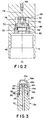
- the stinger initiator section 64 of the stinger internal explosive transfer system 18 is shown in more detail.
- the section 64 is shown adjacent the threads 48 of the bell connector portion 16 of the stinger subassembly.
- the stinger initiator section 64 includes a firing pin housing 66 with initiator retainer 68 that are threaded into the second end 56 of the stinger internal chamber 52 and sealed with initiator O-ring seals 70 and 72.
- the end of the detonating cord 62 is provided with an end seal 74 adjacent the firing pin housing 66.
- a firing pin 76 is mounted within the firing pin housing 66 with shear pins 78.
- the firing pin 76 is adapted to be fired by the detonating cord 62 toward the stinger initiator 80. According to the invention, the initiator 80 is deformed, but not breached by the firing pin 76, thus, a seal between the interior of the bell connector portion 16 is maintained.
- the stinger internal explosive transfer system 18 is adapted to continue and transfer the detonation of the perforating charges from one perforating gun section, through the stinger subassembly 10, and to the next perforating gun section made-up with the bell connector portion 16 of the stinger subassembly 10.
- the interior of the bell connector portion 16 is sealed against well fluids as previously described.
- an alternative structure is provided for a probe portion 12a of a stinger subassembly.
- the probe portion 12a includes an upper end portion 82, which is adapted to receive a disposable end cap 84.
- the upper end portion 82 of the probe portion 12 of the stinger subassembly 10 has the first end 54 of the stinger internal chamber 52 formed therein.
- the stinger receiving initiator charge 60 is positioned within the first end 54 of the stinger internal chamber 52.
- the upper end portion 82 has male threads 86 formed thereon. Beneath the male threads 86 is formed an O-ring groove 88 adapted to receive and trap a sealing O-ring 90.
- the disposable end cap 82 has outer surfaces 20a, 22a, and 24a that substantially conform to the surfaces 20, 22, and 24 previously described for the probe portion 12.
- the disposable end cap 82 also has an end web portion 58a that corresponds to the web portion 58 previously described for the probe portion 12.
- the body of the end cap 82 has a generally bell-shaped interior with a female threaded portion 92.
- the female threaded portion 92 of the end cap 82 is adapted to be threaded onto correspondingly male threaded portion 86 formed on the body of the probe portion 12a.
- Below the female threaded portion 92 is an end cap sealing surface 94, which is adapted to seal against the O-ring 90 positioned in the O-ring groove 88 when the end cap is threaded onto the probe portion 12a.
- the stinger subassembly 10 can be provided with a disposable end cap 82, thereby making the stinger subassembly reusable.
- a latch subassembly 100 according to the presently most preferred embodiment of the invention is shown in an axial cross-section view.
- the latch subassembly 100 has a pin connector portion 102, a body portion 104, spring-loaded stop/release pads 106, a spring-loaded housing 108, collet fingers 110, and a latch internal explosive transfer system 112.
- the latch subassembly 100 is generally symmetrical about its central axis A 2 except as otherwise noted.
- the latch subassembly 100 is shown with its central axis A 2 in a vertical orientation and such that the housing portion 106 is downward. This orientation is how the latch subassembly 100 would normally be oriented for use at the well head of a well.
- references to "upward,” “downward,” “above,” “below,” and other relative terms are understood to be with reference to the orientation of the latch subassembly 100 shown in FIG. 4 of the drawing.
- the pin connector portion 102 is at the upper end of the latch subassembly 100.
- the structure of the pin connector portion 102 can be of a standard form to adapt with correspondingly standard bell connectors on perforating gun sections.
- the pin connector portion 102 of the latch subassembly has an axial pin length L 6 .
- the pin connector portion 102 is a generally tubular body symmetrical about latch axis A 2 and defining an end surface 114, a male threaded pin section 116, a pin ramped surface 118, pin sealing surfaces 120, pin O-ring grooves 122, a pin shoulder surface 124, and a connector centralizer surface 126.
- the pin connector portion 102 is adapted to be made up with a correspondingly structured and threaded bell connector portion of a perforating gun section.
- the pin connector portion 102 and a corresponding bell connector portion of a perforating gun section are moved toward each other, the pin connector portion 102 is guided into the open end section of the bell connector portion.
- the male threaded pin section 116 is made up with the female threaded section of the corresponding bell connector portion.
- the pin ramped surface 118 helps guide the pin connector portion 102 into the open end section of the corresponding bell connector portion.
- the pin O-ring grooves 122 formed in the pin sealing surface 120 are adapted to receive O-rings for helping to seal the pin sealing surface 120 with the bell sealing area of a corresponding bell connector portion of a perforating gun section.
- the pin sealing surface 120 also helps in aligning the latch central axis A 2 of the latch subassembly and its pin connector portion 102 with the corresponding bell connector portion of a perforating gun section.
- the pin end surface 114 and pin shoulder surface 124 provide mechanical stops against over-tightening the threaded connection between the pin connector portion 102 and a corresponding bell connector portion of a perforating gun section.
- the connector centralizer surface 126 having a pin diameter D 8 is adapted to help centralize the latch subassembly 100 within the tubulars of a well bore.
- the lower end of the bell connector portion 102 further has an inwardly facing shelf 128.
- this shelf 128 helps in retaining the spring-loaded stop/release pads on the body portion 104.
- the body portion 104 of the latch subassembly 100 is a structural member attached to the pin connector portion 102.
- the body portion 104 has an upper body portion 130 extending into the pin connector portion 102, a central body portion 132, and a lower body portion 134.
- the upper body portion 130 is for securely mounting the body portion 104 to the pin connector portion 102.
- the spring-loaded stop/release pads 106 are connected to the central body portion 132, and the spring-loaded housing 108 and the collet fingers 110 are mounted to the lower body portion 134.
- the upper body portion 130 is a structural member in the general form of a cylindrical mandrel or other solid structural member adapted for connecting to the pin connector portion 102 of the latch subassembly 100.
- the upper body portion has a male threaded section adapted to be threaded into corresponding female threads formed in the pin connector portion 102.
- the central body portion 132 is a structural member having a generally cylindrical structure with an overall central body diameter D 9 .
- the central body portion 132 is preferably integrally formed with the upper body portion 130.
- the overall central body diameter D 9 is less than the connector centralizer diameter D 8 of the pin connector portion 102 to allow the spring-loaded stop/release pads 106 to be mounted to the outside of the central body portion 132. Nevertheless, the spring-loaded stop/release pads 106 still present an overall profile for the latch subassembly 100 that is not greater than the connector centralizer diameter D 8 .
- the latch subassembly 100 can pass through downhole tubing of a desired size.
- a plurality of alignment bores are formed in the central body portion 132, such as the illustrated two alignment bores 136a and 136b.
- Each of the alignment bores is preferably a cylindrical bore formed in the central body portion 132 and oriented radially about the latch central axis A 2 .
- the alignment bores 136a-b are adapted to help maintain the stop/release pads 106 on the central body portion 132.
- Two additional alignment bores (not shown) are preferably radially oriented 180 degrees from each other and 90 degrees from the alignment bores 136a and 136b, respectively. Thus, a total of four alignment bores are radially spaced apart 90 degrees about the latch central axis A 2 .
- a plurality of spring bores are formed in the central body portion 132, such as the illustrated two upper spring bores 138a-b and the two lower spring bores 140a-b illustrated in FIG. 4.
- Each of the spring bores 138a-b and 140a-b is preferably a cylindrical bore formed in the central body portion 132 and oriented radially about the latch central axis A 2 .
- the upper spring bores 138a-b are each adapted to receive an upper spiral spring 142 therein, and the lower spring bores 140a-b are similarly each adapted to receive a similar spiral spring 144 therein.
- the two upper spring bores 138a and 138b are preferably radially opposed 180 degrees about the latch central axis A 2 as shown in FIG. 4.
- the upper spiral springs 142 positioned in these two upper spring bores can be loaded to exert opposed radial forces.
- Two additional upper spring bores (not shown) are preferably radially oriented 180 degrees from each other and 90 degrees from the upper spring bores 138a and 138b, respectively.
- a total of four upper spring bores are radially spaced apart 90 degrees about the latch central axis A 2 .
- each of the four upper spiral springs 142 (only two shown in FIG. 4) mounted in the upper spring bores can be loaded to exert a force opposed to another upper spiral spring 142 mounted in a radially opposed upper spring bore.
- the two lower spring bores 140a and 140b are preferably radially opposed 180 degrees about the latch central axis A 2 as shown in FIG. 4.
- Two additional lower spring bores (not shown) are preferably radially oriented 180 degrees from each other and 90 degrees from the lower spring bores 140a and 140b, respectively.
- a total of four lower spring bores are radially spaced apart 90 degrees about the latch central axis A 2 .
- each of the four lower spiral springs 144 (only two shown in the FIG. 4) mounted in the lower spring bores are loaded to exert a force opposed to another lower spiral spring 144 mounted in a radially opposed lower spring bore.
- the lower body portion 134 is a structural member having a generally cylindrical structure with a lower body diameter D 10 .
- the lower body portion 134 is secured to the central body portion 132.
- the lower body portion 134 has a collar portion 146, which is preferably integrally formed thereon.
- the collar portion 146 defines an upwardly facing collar shoulder surface 148.
- the collar shoulder surface 148 helps in mounting the spring-loaded housing 108 to the lower body portion 134.
- the collar portion 146 provides added structural material for helping in connecting the spring-loaded housing 108 thereto.
- the bottom end of the lower body portion 134 defines a generally bell-shaped opening 150.
- the bell-shaped opening 150 is adapted to receive the probe tip 20 and the probe first ramped surface 22 of the probe portion 12 of the stinger subassembly 10.
- the bottom end of the lower body portion 134 adjacent the bell-shaped opening 150 has the collet fingers 110 connected thereto.
- the lower body diameter D 10 is preferably substantially the same as the overall central body diameter D 9 for central body portion 132.
- the lower body diameter D 10 of the lower body portion 134 is less than the connector centralizer diameter D 8 of the pin connector portion 102 to allow the spring-loaded housing 108 to be mounted to the outside of the lower body portion 134. Nevertheless, the spring-loaded housing still presents an overall profile for the latch subassembly 100 that is not greater than the connector centralizer diameter D 8 .
- the latch subassembly 100 can pass through downhole tubing of a desired size.
- the diameter of the collar portion 146 although greater than the lower body diameter D 10 , is still less than the connector centralizer diameter D 8 of the pin connector portion 102.
- This smaller diameter allows the spring-loaded housing 108 to be mounted to the outside of the lower body portion 134 yet still present an overall profile for the latch subassembly 100 that is not greater than the connector centralizer D 8 .
- the latch subassembly 100 can pass through downhole tubing of a desired size.
- the spring-loaded stop/release pads 106 are mounted to the central body portion 132. Of the overall length L 5 of the latch subassembly 100, the spring-loaded stop/release pads 106 have an axial pads length L 7 .
- the structure of the spring-loaded stop/release pads 106 is based on a tubular structure divided into four identical portions, as represented in the drawing by the two pads 152a and 152b shown in FIG. 4. All four of the pads 152a-d are shown in FIG. 5. Together, the four pads of the spring-loaded stop/release pads 106 present an overall pads diameter D 11 . The overall pads diameter D 11 of the spring-loaded stop/release pads 106 is not greater than the connector centralizer diameter D 8 of the pin connector portion 102. Thus, the latch subassembly 100 can pass through downhole tubing of a desired size. As best shown in FIG. 5, the four pads 152a-d are positioned on the central body portion 132 over the radially oriented springs, such as upper springs 142. Thus, the springs 142 exert radially outward forces on the pads 152a-d.
- each of the pads as shown in FIG. 4 for the two pads 152a and 152b, also includes a peg 154a and 154b, respectively, adapted to fit within any of the four alignment bores, such as illustrated in FIG. 4 for the alignment bores 136a and 136b.
- the pegs help in retaining the vertical position of the pads on the central body portion 132.
- each of the pads extend into the shelf 128 of the pin connector portion 102. This helps in retaining the pads against the springs 142 and 144.
- the lower end of each of the pads is formed a shallow recess 156a and 156b, respectively.
- the shallow recesses are identically positioned on each of the pads such that when the four pads are positioned about the central body portion 132, the recesses define an at least partially circumferential recess.
- the recesses are adapted to position a tubular collar 158 over the lower end of the pads 152a-d.
- the cooperation of the shallow recesses with the tubular collar 158 retains the four pads, represented by pads 152a and 152b, against the upper springs 142 and lower springs 144. Thereby, the four pads are spring-loaded to the central body portion 132.
- the body portion 104 is separated from the bell connector portion 102.
- the plurality of upper springs 142 are positioned in the upper spring bores 138a-d of the central body portion 132 as shown in FIGS. 4 and 5, and the plurality of lower springs 144 are positioned in the lower spring bores of central body portion, as shown in FIG. 4 for lower spring bores 140a-b.
- the pads 152a-d are then positioned over the central body portion 132, such that the peg 154 of each pad is positioned in one of the alignment bores, as shown in FIG. 4 for alignment bores 136a-b.
- the tubular collar 158 is positioned over the pads as shown in FIG.
- the spring-loaded housing 108 is mounted on the lower body portion 134.
- the overall housing diameter D 12 of the spring-loaded housing 108 is not greater than the pin centralizer diameter D 8 , whereby the latch subassembly 100 can pass through downhole tubing of a desired size.
- the housing 108 is spaced apart from the lower end of the spring-loaded stop/release pads 106 by an axial spacing length L 8 .
- the spring-loaded housing 108 is adapted to be axially moved upward on the lower body portion 134, first to close the axial spacing length L 8 , and then to overlap with the lower end of the spring-loaded stop/release pads 106.
- the spring-loaded housing 108 has an axial length L 9 .
- the spring-loaded housing 108 includes a substantially tubular housing member 160 adapted to slide over the lower body portion 134.
- the tubular housing member 160 is preferably formed in two sections, an upper housing portion 160a and a lower housing portion 160b.
- the tubular housing member 160 has an inner diameter that is larger than the lower body diameter D 10 of the lower body portion 134, but adapted to slide over the collar portion 146 of the lower body portion 134.
- the upper end of the first annular space 162 is open.
- the tubular member 160 has an inwardly facing flange 164 that can slide with the tubular member 160 along the lower body portion 134 and defines the lower end of the first annular space 162.
- the first annular space 162 is adapted to move over the lower ends of the four pads 152a-d when the pads are radially compressed against the springs 142 and 144 such that the pads 152a-d present a smaller diameter profile.
- the flange 164 defines the upper end of a second annular space 166.
- the lower end of the second annular space 166 is defined by the upwardly facing collar shoulder surface 148 on the collar portion 146 of the lower body portion 134.
- the housing spring 168 which is trapped at its lower end by the upwardly facing collar shoulder surface 148 of the collar portion 146, exerts an upward force against the flange 164 of the tubular housing member 160. This upward force exerted by the spring 168 is parallel to the latch central axis A 2 .
- One or more retaining pins, such as screws 170 are tapped or threaded through the tubular housing member 160 and into the collar portion 146 of the lower body portion 134.
- the retaining screws 170 retain the tubular housing member over the lower body portion 134 against the force of the housing spring 168 positioned within the second annular space 166.
- the lower end of the tubular housing member 160 has an inwardly facing deflecting structure 172, which is for engaging the collet fingers 110 with the stinger subassembly 10 as will hereinafter be described in detail.
- the deflecting structure 172 has a deflecting first ramped surface 174, an engaging surface 176, and a deflecting second ramped surface 178.
- the deflecting first ramped surface 174 is frusto-conical and reduces in diameter downward along the axis A 2 of the latch subassembly 100.
- the engaging surface 176 defines an inner cylindrical wall below the deflecting first ramped surface 174.
- the deflecting second ramped surface 178 is frusto-conical and expands in diameter downward along the axis A 2 of the latch subassembly 100.
- the tubular housing member 160 is preferably formed into two portions, upper housing portion 160a and lower housing portion 160b.
- the upper housing portion 160a and the lower housing portion 160b are threaded together and retained with one or more set screws 180.
- This separable housing structure permits the latch assembly 100 to be more easily assembled.
- the lower body portion 134 is removed from the central body portion 132, so that the upper housing portion 160a can be placed over the lower body portion 134 from its upper end. Otherwise, if the lower housing portion 160b were integrally formed with the upper housing portion 160a, the deflecting structure 172 would not slide over the diameter of the collar portion 146 on the lower body portion 134.
- a housing snap-ring seal 181 is provided between the lower body portion 134 and the tubular housing member 160 to prevent the housing from moving downward and accidentally releasing while running into and out of the well.
- the snap-ring 181 expands beyond the inside diameter of the pin threads on housing 160a.
- the lower body portion 134 is separated from the central body portion 132.
- the housing spring 168 is positioned over the lower body portion 132 and slid downward until it is stopped by the upwardly facing collar shoulder surface 148 on the collar portion 146 of the lower body portion 134.
- the upper housing portion 160a is then positioned over the lower body portion 132 and slid downward such that the inwardly facing flange 164 compresses the spring 168 as shown in FIG. 4.
- the one or more retaining screws 170 are tapped or threaded through the tubular housing member 160 and into the collar portion 146 of the lower body portion 134.
- the retaining screws 170 retain the tubular housing member over the lower body portion 134 against the force of the housing spring 168 positioned within the second annular space 166.
- the lower housing portion 160b is slid upward from the lowermost end of the lower body portion 134. Then the lower housing portion 160b is threaded to the upper housing portion 160a and retained with one or more set screws 180.
- the collet fingers 110 of the latch subassembly 100 are attached to the lower body portion 134. At least two collet fingers 110, such as the first and second collet fingers 182a and 182b are employed. However, it is to be understood that additional collet fingers can be used, which may be particularly desirable for a larger latch subassembly for use in larger downhole tubing applications.
- the arcuate extension of each of the collet fingers 182a and 182b is a matter of design choice, and is expected to range up to nearly 90 degrees of radial arc about the latch axis A 2 . Thus, if desired, four or more collet fingers 110 can be employed in the latch subassembly 100.
- each of the individual collet fingers as represented by collet fingers 182a and 182b, has a dog portion 184 and a finger tip portion 186.
- each collet finger 182a-b is an extension of the lower body portion 134.
- the dog portion 184 is adapted to be sufficiently deformable to be deflected inward or outward relative to the relaxed position shown in FIG. 4 of the drawing.
- the dog portion 184 of each collet finger 182a-b can be pivotally mounted to the lower body portion 134 adjacent the bottom of the bell-shaped opening 150.
- the finger tip portion 186 of each of the collet fingers 182a-b has a plurality of surfaces adapted to be deflected by and engage with other surfaces of the stinger subassembly 10 and the latch subassembly 100.
- the finger tip portion of each of the collet fingers 182a-b has a first outwardly facing ramped surface 188, an outwardly facing vertical surface 190, a second outwardly facing ramped surface 192, a first inwardly facing ramped surface 194, an inwardly facing vertical surface 196, and a second inwardly facing ramped surface 198.
- the cooperation of these surfaces 188-198 with other surfaces and structures will hereinafter be described in more detail.
- the latch internal explosive transfer system 112 is preferably located centrally within the latch subassembly 100.
- the latch internal explosive transfer system 112 includes a latch internal chamber 200.
- the chamber 200 extends from a first end 202 adjacent the end surface 114 of the pin connector portion 102 and through the entire body portion 104 to a second end 204 adjacent the bell-shaped opening 150 of the lower body portion 134.
- a latch receiving booster charge 206 Positioned within the latch internal chamber 200 adjacent the first end 202 is a latch receiving booster charge 206.
- a latch detonating cord 208 is positioned through substantially the entire length of the chamber 200.
- a latch booster charge 210 and a downward focused shaped charge 212 are positioned in the chamber 200 adjacent the second end 204 of the chamber 200.
- the latch internal explosive transfer system 112 is adapted to continue and transfer the detonation of the perforating charges from one perforating gun section made-up with the pin connector portion 102 of the latch subassembly 100, through the latch subassembly 100, and to a stinger subassembly 10 latched to the latch subassembly 100.
- the stinger subassembly 10 in turn continues and transfers the detonation to the next perforating gun section made-up with the bell connector portion 16 of the stinger subassembly 10.
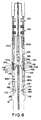
- the stinger subassembly 10 is shown as it is positioned when the slip landing surface 40 of the slip landing portion 14 are held by the seal/slip rams of a blowout preventer (not shown).
- the stinger subassembly 10 has already been made up with a lower perforating gun section (not shown), which has been inserted through the blowout preventer seal/slip rams.
- the latch subassembly 100 has been made up with an upper perforating gun section (not shown), which has been moved into a lubricator above the blowout preventer.
- the upper perforating gun section with the latch subassembly 100 at the lower end thereof is then lowered through the blowout preventer onto the probe portion 12 of the stinger subassembly 10.
- the latch subassembly 100 is lowered until the deflecting structure 172 of the spring-loaded housing 108 is stopped by the second shoulder surface 34 above the centralizer surface 36 of the stinger subassembly 10, as shown in FIG. 7.
- the tip 20 of the probe portion 12 of the stinger subassembly 10 is slightly spaced apart from the upper end of the bell-shaped opening 150 formed in the lower body portion 134.
- the finger tip portion 186 of each of the individual collet fingers 182a and 182b can at least partially begin to be deflected into the recess 28 of the probe portion 12 on the stinger subassembly 10.
- the housing spring 168 is trapped in the second annular space 166 defined by the lower body portion 134, the tubular housing member 160, and the flange 164. As previously described, the potential energy of the housing spring 168 is retained by the retaining screws 170 threaded through the tubular housing portion 160 into the collar portion 146 of the lower body portion 134.
- a downward force is applied to the latch subassembly 100.
- This force is transmitted axially through the latch subassembly 100 to the lower body portion, through the retaining screws 170, through the spring-loaded housing 108 at the deflecting structure 172 to the second shoulder surface 34 above the centralizer surface 36 of the stinger subassembly 10.
- a sufficiently strong downward force is applied to the latch subassembly that the retaining screws 170 are sheared between tubular housing member 160 and the lower body portion 134. Once the retaining screws 170 have been sheared, the tubular housing member 160 is released from the lower body portion 134.
- the housing spring 168 which is trapped between the surface 148 of the collar portion 146 of the lower body portion 134 and the flange 164 of the tubular housing member 160, is now free to drive the slidably mounted tubular housing body 160 upward on the lower body portion 134.
- the latch subassembly 100 is shown in a latched position on the stinger subassembly 10.
- Each of the retaining screws 170 are shown as having been sheared into two portions.
- An outer portion 170a of the sheared retaining screw travels with the upwardly moving tubular housing member 160.
- An inner portion 170b of the sheared retaining screw remains with the collar portion 146 of the lower body portion 134.
- the upward movement of the tubular housing member 160 on the lower body portion 134 permits the latch subassembly 100 to settle onto the tip 20 of the probe portion 12 of the stinger subassembly 10.
- the tubular housing member 160 moves upward on the lower body portion 134 until it is stopped by the pads, such as pads 152a-b, of the spring-loaded stop/release pads 106. At this point, the potential energy of the housing spring 168 is only partially released in driving the tubular housing member 160 upward. The upward movement of the tubular housing member 160 also causes the deflecting structure 172 to force and deflect the collet fingers inward.
- the deflecting first ramped surface 174 of the deflecting structure 172 engages the second outwardly facing ramped surface 192 of the finger tip portion 186 inward
- the finger tip portion 186 of each of the collet fingers 182a and 182b are deflected into the probe recess 28 of the probe portion 12 of the stinger subassembly 10.
- the various surfaces on the probe portion 12 of the stinger subassembly and the deflecting structure 172 of the tubular housing member cooperate to trap the finger tip portions 186 of the collet fingers 182a-b in the probe recess 28.
- the latch subassembly 100 is securely latched onto the probe portion 12 of the stinger subassembly. This process of latching the latch subassembly 100 to the stinger subassembly 10 can be accomplished in a matter of seconds.
- the stinger subassembly 10 and the latch subassembly 100 form a completed connection between the lower and upper perforating gun sections (not shown).
- the perforating gun sections can then be lowered downhole to perforate the well.
- a detonating signal can be transmitted from the latch subassembly 100 to the stinger subassembly 10.
- a detonating signal is transmitted from an upper perforating gun to the latch internal explosive transfer system 112 of the latch subassembly 100.
- the detonating signal from the upper perforating gun detonates the latch receiving booster charge 206.
- the booster charge 206 in turn ignites the latch detonating cord 208 positioned within the latch internal chamber 200.
- the latch detonating cord 208 transfers the detonating signal to the latch booster charge 210, which detonates the latch downward focused shaped charge 212.
- the shaped charge 212 pierces the web material of the lower body portion 134 below the second end 204 of the chamber 200 and fires through the stinger tip web 58 of the stinger subassembly 10 that is latched to the latch subassembly 100.
- the tip 20 of the probe 12 of the stinger subassembly 10 is preferably flush with the inner surface of the bell-shaped opening 150 of the lower body portion 134 of the latch subassembly 100.
- the latch shaped charge 212 pierces through the thickness of the web material 58 defining the tip 20 of the probe portion 12.
- the latch downward focused shaped charge 212 is adapted to pierce the tip 20 of the subassembly 10.
- the latch downward focused shape charge 212 pierces the disposable end cap 84.
- FIG. 1 of the drawing which shows the stinger subassembly 10 in detail
- piercing the web material 58 defining the tip 20 of the probe portion 12 initiates the stinger internal explosive transfer system 18. More particularly, the latch shaped charge 212 pierces the material to initiate the stinger booster charge 60.
- the stinger booster charge 60 in turn ignites the stinger detonating cord 62 within the stinger internal chamber 52.
- the stinger detonating cord 62 transfers the detonating signal to the stinger initiator section 64, best shown in FIG. 2.
- the firing pin 76 mounted within the firing pin housing 66 is fired by the detonating cord 62 toward the stinger initiator 80.
- the initiator 80 is deformed, but not breached by the firing pin 76, thus, a seal between the interior of the stinger internal chamber 52 and the bell connector portion 16 is maintained.
- the deforming material of the initiator drives downward to detonate the initiator.
- This detonation of the initiator initiates a booster charge in a perforating gun section connected to the bell connector portion 16 of stinger subassembly 10.
- the detonating signal is transferred from the stinger subassembly 10 to a booster charge and detonating cord in the lower perforating gun section (not shown).
- the detonating cord in the lower perforating gun section serially detonates the perforating charges in that perforating gun section.
- the detonating signal is carried through the successive connections as described herein.
- the perforating gun sections After the perforating gun sections have been detonated downhole to perforate the well, they are raised back toward the well head.
- the second (upper) perforating gun section is raised through the blowout preventer stack until the slip landing portion 14 of the stinger subassembly 10 aligns with the seal/slip rams of the blowout preventer stack.
- the seal/slip rams of the blowout preventer stack are engaged to seal and hold the perforating gun section string at the stinger subassembly 10.
- the latch subassembly 100 can be removed from the stinger subassembly 10 without allowing any fluid to escape through the seal/slip rams of the blowout preventer stack.
- a clamp or the operating rams of another blowout preventer above the seal/slip rams in the blowout preventer stack are employed to release the latch subassembly 100 from the stinger subassembly 10.
- the term "operating" rams refers to any of a number of different types of rams that are usually employed above the seal/slip rams, except shearing or other type rams that would undesirably damage the latch subassembly. Referring to FIG. 8, the operating rams engage the spring-loaded stop/release pads 106 and radially compress the pads 152a-b toward the latch central axis A 2 .
- the latch subassembly is shown in a released position.
- the housing spring 168 maintains the tubular housing member 160 over the pads 152a-d, which retains them in the reduced diameter form against the opposing forces of the springs 142 and 144 of the spring-loaded latch pads 106.
- the further upward movement of the tubular housing member 160 also causes the deflecting structure 172 to move upward. This releases the finger pads 186 of the collet fingers 182a-b, such that the latch subassembly 100 can be lifted off the probe portion 12 of the stinger subassembly 10.
- the probe second ramp surface 26 deflects the second inwardly facing ramped surface 188 of the finger tip portion 186 of each of the collet fingers 182a-b.
- the finger tip portion 186 of each of the collet fingers 182a-b is deflected out of the probe recess 28 of the probe portion 12 of the stinger subassembly 10.
- the particular dimensions of the stinger subassembly 10 and latch subassembly 100 according to this invention are a matter of engineering design choice depending on many parameters. Such parameters, include, for example, the particular size of the well tubing and casing in which the stinger subassembly is to be used.
- the stinger subassembly 10 and latch subassembly 100 can be designed, for example, for use in 5-inch tubing.
- this illustrative example is for the purposes of more fully describing the presently most preferred embodiment of the invention, but not to limit the invention to the particular dimensions of such a disclosed preferred embodiment.
- the stinger subassembly 10 can have, for example, the following basic dimensions: an overall axial stinger length L 1 of about 24 inches (61 cm), an axial probe length L 2 of about 10 inches (26 cm); an axial landing length L 3 of about 10 inches (26 cm); an axial bell length L 4 of about 5 inches (13 cm); a tip diameter D 1 of about 1 inches (2.5 cm); a shank diameter D 2 of about 2 inches (5 cm); a recess diameter D 3 of about 1.5 inches (4 cm); a probe landing diameter D 4 of about 2.5 inches (6.5 cm); a centralizer diameter D 5 of about 3.5 inches (9 cm); a slip landing diameter D 6 of about 3 inches (8 cm); and a bell diameter D 7 of about 3.5 inches (9 cm).
- the latch subassembly 100 can have, for example, the following basic dimensions: an overall axial latch length L 5 of about 30 inches (76 cm); an axial pin length L 6 of about 8 inches (20 cm); an axial pads length L 7 of about 9 inches (22 cm); an axial spacing length L 8 of about 1.2 inches (3 cm); an axial housing length L 9 of about 12 inches (30 cm); a pin diameter D 8 of about 3.5 inches (9 cm); an overall central body diameter D 9 of about 3.2 inches (8 cm); a lower body diameter D 10 of about 2.2 inches (5.5 cm); an overall pads diameter D 11 of about 3.2 inches (8 cm); and an overall housing diameter D 12 of about 3.5 inches (9 cm).
Landscapes
- Life Sciences & Earth Sciences (AREA)
- Engineering & Computer Science (AREA)
- Geology (AREA)
- Mining & Mineral Resources (AREA)
- Environmental & Geological Engineering (AREA)
- Fluid Mechanics (AREA)
- Physics & Mathematics (AREA)
- General Life Sciences & Earth Sciences (AREA)
- Geochemistry & Mineralogy (AREA)
- Mechanical Engineering (AREA)
- Marine Sciences & Fisheries (AREA)
- Quick-Acting Or Multi-Walled Pipe Joints (AREA)
- Manufacturing Of Electrical Connectors (AREA)
Claims (14)
- Connecteur d'outil comprenant : une élinde flottante (10); un réceptacle pour élinde flottante (100); l'élinde flottante (10) étant adaptée pour s'enficher dans le réceptacle pour élinde flottante (100) ; un élément d'engagement sous contrainte (172) mobile entre une position de descente avant l'enfichage de l'élinde flottante (10) dans le réceptacle pour élinde flottante (100) et une position verrouillée dans laquelle l'élinde flottante (10) est enfichée dans le réceptacle pour élinde flottante (100) pour solidariser l'élinde flottante (10) et le réceptacle pour élinde flottante (100) ; et un élément de libération (170) retenant l'élément d'engagement sous contrainte (172) dans la position de descente, caractérisé en ce que, lorsque l'élinde flottante (10) est enfichée dans le réceptacle pour élinde flottante (100) et qu'une force déterminée est appliquée à l'élinde flottante (10) et au réceptacle pour élinde flottante (100), l'élément de libération (170) libère l'élément d'engagements sous contrainte (172) pour adopter la position verrouillée et solidariser ainsi l'élinde flottante (10) et le réceptacle pour élinde flottante (100).
- Connecteur selon la revendication 1, dans lequel l'outil est un perforateur à balles.
- Connecteur selon la revendication 1 ou 2, comprenant en outre : un élément de butée amovible (106) pour bloquer l'élément d'engagement (172) dans la position verrouillée, tandis que si l'élément de butée (106) est relâché, l'élément d'engagement (172) adopte une position relâchée de telle sorte que l'élinde flottante (10) et le réceptacle pour élinde flottante (100) deviennent séparables.
- Connecteur selon la revendication 2, dans lequel l'élément de butée amovible est adapté pour être libéré par un collier de serrage.
- Connecteur selon la revendication 1, 2, 3 ou 4, dans lequel l'élément d'engagement sous contrainte (172) est monté sur le réceptacle pour élinde flottante (100).
- Connecteur selon l'une quelconque des revendications précédentes, dans lequel l'élinde flottante (10) comporte une sous-ensemble d'élinde flottante (10) possédant :dans lequel le réceptacle pour élinde flottante (100) comprend un sous-ensemble de loquet (100) possédant:(i) une partie sonde (12) ; et(ii) une partie connecteur sur élinde flottante (16) raccordée à la partie sonde (12), la partie connecteur sur élinde flottante (16) étant adaptée pour constituer le sous-ensemble d'élinde flottante (10) avec un premier outil ou première section de perforateur à balles ; ettandis que dans la position de descente, le logement monté sur ressort (108) du sous-ensemble de loquet (100) est retenu dans une position de descente pour être posé sur la partie sonde (12) du sous-ensemble d'élinde flottante (10) ; et tandis que si une force déterminée est appliquée au sous-ensemble de loquet (100) contre le sous-ensemble d'élinde flottante (10), la force déterminée cisaille la goupille de retenue (170) pour libérer le logement monté sur ressort (108), qui se trouve repoussé sur la partie corps (104) vers la position verrouillée pour que la structure déviatrice (172) du logement monté sur ressort (108) dévie les doigts de serrage (110) pour les engager dans la partie sonde (12) du sous-ensemble d'élinde flottante (10) et retienne les doigts de serrage (110) en engagement verrouillé avec la partie sonde (12).(i) une partie corps (104), la partie corps (104) étant adaptée pour recevoir la partie sonde (12) du sous-ensemble d'élinde flottante (10) ;(ii) une partie connecteur de loquet (102) raccordée à la partie corps (104), la partie connecteur de loquet (103) étant adaptée pour constituer le sous-ensemble de loquet (100) avec un second outil ou seconde section de perforateur à balles ;(iii) un logement monté sur ressort (108) monté pour coulisser sur la partie corps (104), le logement monté sur ressort (108) adapté pour passer de force d'une position de descente à une position verrouillée, le logement monté sur ressort (108) possédant au moins une goupille de retenue (170) pour retenir le logement monté sur ressort (108) dans la position de descente sur la partie corps (104) jusqu'à ce que la goupille de retenue (170) soit cisaillée ; et(iv) des doigts de serrage (110) connectés à la partie corps (104) sensiblement à l'intérieur du logement monté sur ressort (108), le logement monté sur ressort (108) ayant une structure déviatrice (172) adaptée pour dévier les doigts de serrage (110) afin de les engager dans la partie sonde (12) du sous-ensemble d'élinde flottante (10),
- Connecteur selon la revendication 6, dans lequel le sous-ensemble d'élinde flottante (10) comprend en outre un système de transfert d'explosif (18) interne à l'élinde flottante.
- Connecteur selon la revendication 6, dans lequel le sous-ensemble de loquet (100) comprend en outre un système de transfert d'explosif interne (112) qui comprend :tandis que le système de transfert d'explosif interne de loquet (112) est adapté pour continuer le transfert les charges perforatrices depuis le premier outil ou la première section de perforateur à balles, à travers le sous-ensemble de loquet (100), et pour tirer la charge en forme de loquet (212) vers la partie sonde (12) du sous-ensemble sur élinde flottante (10).(a) une chambre interne de loquet (200) s'étendant à travers la partie connecteur de loquet (102) et à travers la partie corps (104) ;(b) une charge de réception de loquet (206) positionnée dans la chambre interne de loquet (200) adjacente à la partie connecteur de loquet (102) ;(c) un cordon détonateur de loquet (208) positionné sensiblement sur toute la longueur de la chambre interne de loquet (200) ;(d) une charge d'envoi de loquet (210) positionnée dans la chambre interne de loquet (200) adjacente à la partie corps (104) ; et(e) une charge en forme de loquet (212) positionnée dans la chambre interne de loquet (200) proche de la charge d'envoi de loquet (210) ;
- Connecteur selon la revendication 8, dans lequel le sous-ensemble d'élinde flottante (10) comprend en outre un système de transfert explosif interne sur élinde flottante (18) possédant :tandis que le système de transfert explosif interne sur élinde flottante (18) est adapté pour être déclenché par le système de transfert d'explosif interne (112) pour continuer le transfert de la détonation des charges perforatrices depuis le sous-ensemble à loquet (100), à travers le sous-ensemble sur élinde flottante (10), vers la seconde partie d'outil ou la seconde section de perforateur à balles constituée avec la partie connecteur sur élinde flottante (16) du sous-ensemble sur élinde flottante (10).(a) une chambre interne sur élinde flottante (52) s'étendant depuis un point adjacent à une pointe d'extrémité (54) de la partie sonde (12) vers la partie connecteur sur élinde flottante (16) ;(b) une charge sur élinde flottante (60) positionnée dans la chambre interne sur élinde flottante (52) adjacente à la pointe d'extrémité (54) de la partie sonde (12) ;(c) un cordon détonateur sur élinde flottante (62) positionné sensiblement sur toute la longueur de la chambre interne sur élinde flottante (52) ;(d) un percuteur sur élinde flottante (76) positionné dans la chambre interne sur élinde flottante (52) ; et(e) une amorce (80) sur élinde flottante ;
- Connecteur selon l'une quelconque des revendications 1 à 5, dans lequel l'élinde flottante (10) comprend un sous-ensemble d'élinde flottante (10) possédant :dans lequel le réceptacle pour élinde flottante (100) comprend un sous-ensemble de loquet (100) possédant :(i) une partie sonde (12) ; et(ii) des moyens pour raccorder la partie sonde (12) à un premier outil ou première section de perforateur à balles ; ettandis que si une force déterminée est appliquée au sous-ensemble de verrouillage (106) contre le sous-ensemble d'élinde flottante (10), la force déterminée cisaille les moyens de retenue du logement monté sur ressort (108) de sorte que le logement monté sur ressort (108) se trouve repoussé sur la partie corps (104) vers la position verrouillée.(i) une partie corps (104), la partie corps (104) étant adaptée pour recevoir la partie sonde (12) du sous-ensemble d'élinde flottante (10) ;(ii) des moyens pour raccorder la partie corps (104) à un second outil ou seconde section de perforateur à balles ;(iii) un logement monté sur ressort (108) monté pour coulisser sur la partie corps (104), le logement monté sur ressort (108) adapté pour passer de force d'une position de descente à une position verrouillée,(iv) des moyens pour retenir le logement monté sur ressort (108) dans la position de descente sur la partie corps (104) ; et(v) des moyens pour verrouiller la partie corps (104) sur la partie sonde (12) du sous-ensemble d'élinde flottante (10) lorsque le logement monté sur ressort (108) est déplacé vers la position verrouillée ;
- Procédé de raccordement d'une première section d'outillage à une seconde section d'outillage, procédé comprenant les phases suivantes :(a) raccordement d'une élinde flottante (10) à la première section d'outillage ;(b) raccordement d'un réceptacle pour élinde flottante (100) à la seconde section d'outillage ;(c) enfichage de l'élinde flottante (10) pour s'emboíter dans le réceptacle pour élinde flottante (100) caractérisé en ce que le procédé comprend en outre les étapes suivantes :(d) application d'une force déterminée à l'élinde flottante (10) et au réceptacle pour élide flottante (100) pour libérer un élément d'engagement sous contrainte (172) depuis une position de descente vers une position verrouillée pour solidariser ainsi l'élinde flottante (10) et le réceptacle pour élinde flottante (100).
- Procédé selon la revendication 12, dans lequel la première section d'outillage est une première section de perforateur à balles et la seconde section d'outillage est une seconde section de perforateur à balles.
- Procédé selon la revendication 11 ou 12, comportant en outre la phase de serrage d'un élément de butée amovible pour libérer l'élément d'engagements sous contrainte de la position verrouillée de sorte que l'élinde flottante (10) et le réceptacle pour élinde flottante (100) deviennent séparables.
- Procédé selon la revendication 13, dans lequel la phase de serrage de l'élément de butée amovible pour libérer l'élément d'engagement sous contrainte consiste à faire appel à un système de serrage manuel, ou bien aux coulisseaux d'un bloc-obturateur de puits.
Applications Claiming Priority (4)
| Application Number | Priority Date | Filing Date | Title |
|---|---|---|---|
| US698608 | 1996-08-16 | ||
| US08/698,608 US5823266A (en) | 1996-08-16 | 1996-08-16 | Latch and release tool connector and method |
| US08/698,603 US5778979A (en) | 1996-08-16 | 1996-08-16 | Latch and release perforating gun connector and method |
| US698603 | 1996-08-16 |
Publications (3)
| Publication Number | Publication Date |
|---|---|
| EP0825324A2 EP0825324A2 (fr) | 1998-02-25 |
| EP0825324A3 EP0825324A3 (fr) | 2000-04-19 |
| EP0825324B1 true EP0825324B1 (fr) | 2004-11-17 |
Family
ID=27106245
Family Applications (1)
| Application Number | Title | Priority Date | Filing Date |
|---|---|---|---|
| EP19970306247 Expired - Lifetime EP0825324B1 (fr) | 1996-08-16 | 1997-08-18 | Connecteur pour outils |
Country Status (2)
| Country | Link |
|---|---|
| EP (1) | EP0825324B1 (fr) |
| DE (1) | DE69731591T2 (fr) |
Cited By (1)
| Publication number | Priority date | Publication date | Assignee | Title |
|---|---|---|---|---|
| DE102005058356A1 (de) * | 2004-12-13 | 2007-06-21 | Dynaenergetics Gmbh & Co. Kg | Sichere Übertragung der Zündung bei Perforationssystemen |
Families Citing this family (6)
| Publication number | Priority date | Publication date | Assignee | Title |
|---|---|---|---|---|
| US6006833A (en) * | 1998-01-20 | 1999-12-28 | Halliburton Energy Services, Inc. | Method for creating leak-tested perforating gun assemblies |
| US7210524B2 (en) | 2002-11-07 | 2007-05-01 | Baker Hughes Incorporated | Perforating gun quick connection system |
| RU2499123C2 (ru) * | 2011-06-22 | 2013-11-20 | Валерий Владимирович Попов | Пружинный центратор с автоматической фиксацией на обсадной колонне |
| US9982517B2 (en) * | 2014-06-27 | 2018-05-29 | Owen Oil Tools Lp | Coiled tubing connector for downhole tools |
| CN113123746B (zh) * | 2020-01-10 | 2024-07-16 | 成都百胜野牛科技有限公司 | 一种井下施放器及井下工具组合体 |
| CN116084867A (zh) * | 2021-11-05 | 2023-05-09 | 中国石油化工股份有限公司 | 一种泄油器的开泄器释放装置 |
Family Cites Families (9)
| Publication number | Priority date | Publication date | Assignee | Title |
|---|---|---|---|---|
| US4436157A (en) * | 1979-08-06 | 1984-03-13 | Baker International Corporation | Latch mechanism for subsea test tree |
| US4305465A (en) * | 1980-02-01 | 1981-12-15 | Dresser Industries, Inc. | Subsurface tubing hanger and stinger assembly |
| US4391326A (en) * | 1981-01-22 | 1983-07-05 | Dresser Industries, Inc. | Stinger assembly for oil well tool |
| US4449736A (en) * | 1981-12-16 | 1984-05-22 | Dresser Industries, Inc. | Releasable tubing string connector |
| US5111884A (en) * | 1991-07-10 | 1992-05-12 | Halliburton Company | Method and apparatus for reworking wells |
| US5273121A (en) * | 1992-04-03 | 1993-12-28 | Eastern Oil Tools Pte Ltd. | Intercarrier mechanism for connecting and orienting tubing conveyed perforating guns |
| US5398760A (en) * | 1993-10-08 | 1995-03-21 | Halliburton Company | Methods of perforating a well using coiled tubing |
| US5529127A (en) * | 1995-01-20 | 1996-06-25 | Halliburton Company | Apparatus and method for snubbing tubing-conveyed perforating guns in and out of a well bore |
| US5518072A (en) * | 1995-01-30 | 1996-05-21 | Camco International Inc. | Downhole tool for assisting in separating and reconnecting well tubing |
-
1997
- 1997-08-18 DE DE69731591T patent/DE69731591T2/de not_active Expired - Fee Related
- 1997-08-18 EP EP19970306247 patent/EP0825324B1/fr not_active Expired - Lifetime
Cited By (1)
| Publication number | Priority date | Publication date | Assignee | Title |
|---|---|---|---|---|
| DE102005058356A1 (de) * | 2004-12-13 | 2007-06-21 | Dynaenergetics Gmbh & Co. Kg | Sichere Übertragung der Zündung bei Perforationssystemen |
Also Published As
| Publication number | Publication date |
|---|---|
| EP0825324A3 (fr) | 2000-04-19 |
| DE69731591T2 (de) | 2005-03-31 |
| DE69731591D1 (de) | 2004-12-23 |
| EP0825324A2 (fr) | 1998-02-25 |
Similar Documents
| Publication | Publication Date | Title |
|---|---|---|
| US5823266A (en) | Latch and release tool connector and method | |
| US5778979A (en) | Latch and release perforating gun connector and method | |
| US5529127A (en) | Apparatus and method for snubbing tubing-conveyed perforating guns in and out of a well bore | |
| US11634956B2 (en) | Detonation activated wireline release tool | |
| US5803175A (en) | Perforating gun connection and method of connecting for live well deployment | |
| US5984006A (en) | Emergency release tool | |
| US7013977B2 (en) | Sealed connectors for automatic gun handling | |
| US3712376A (en) | Conduit liner for wellbore and method and apparatus for setting same | |
| CA2518344C (fr) | Liberation automatique d'outil | |
| EP0647765A2 (fr) | Procédé pour la perforation d'un puits avec utilisation d'un tubage flexible | |
| US5423382A (en) | Apparatus for releasing perforating gun equipment from a well casing | |
| US5370186A (en) | Apparatus and method of perforating wellbores | |
| EP0825324B1 (fr) | Connecteur pour outils | |
| US6953141B2 (en) | Joining of tubulars through the use of explosives | |
| GB2440846A (en) | Explosively cutting and removing a downhole anchor in a single trip | |
| CA2260934C (fr) | Outil de deverrouillage d'urgence perfectionne | |
| GB2329661A (en) | Perforating gun connection for live well deployment | |
| GB2415452A (en) | Explosive welding of pipes |
Legal Events
| Date | Code | Title | Description |
|---|---|---|---|
| PUAI | Public reference made under article 153(3) epc to a published international application that has entered the european phase |
Free format text: ORIGINAL CODE: 0009012 |
|
| AK | Designated contracting states |
Kind code of ref document: A2 Designated state(s): DE GB NL |
|
| AX | Request for extension of the european patent |
Free format text: AL;LT;LV;RO;SI |
|
| PUAL | Search report despatched |
Free format text: ORIGINAL CODE: 0009013 |
|
| RIC1 | Information provided on ipc code assigned before grant |
Free format text: 7E 21B 17/04 A, 7E 21B 43/116 B, 7E 21B 17/06 B, 7E 21B 23/04 B |
|
| AK | Designated contracting states |
Kind code of ref document: A3 Designated state(s): AT BE CH DE DK ES FI FR GB GR IE IT LI LU MC NL PT SE |
|
| AX | Request for extension of the european patent |
Free format text: AL;LT;LV;RO;SI |
|
| 17P | Request for examination filed |
Effective date: 20000628 |
|
| AKX | Designation fees paid |
Free format text: DE GB NL |
|
| 17Q | First examination report despatched |
Effective date: 20020611 |
|
| GRAP | Despatch of communication of intention to grant a patent |
Free format text: ORIGINAL CODE: EPIDOSNIGR1 |
|
| GRAS | Grant fee paid |
Free format text: ORIGINAL CODE: EPIDOSNIGR3 |
|
| GRAA | (expected) grant |
Free format text: ORIGINAL CODE: 0009210 |
|
| AK | Designated contracting states |
Kind code of ref document: B1 Designated state(s): DE GB NL |
|
| REG | Reference to a national code |
Ref country code: GB Ref legal event code: FG4D |
|
| REF | Corresponds to: |
Ref document number: 69731591 Country of ref document: DE Date of ref document: 20041223 Kind code of ref document: P |
|
| PGFP | Annual fee paid to national office [announced via postgrant information from national office to epo] |
Ref country code: DE Payment date: 20050811 Year of fee payment: 9 |
|
| PLBE | No opposition filed within time limit |
Free format text: ORIGINAL CODE: 0009261 |
|
| STAA | Information on the status of an ep patent application or granted ep patent |
Free format text: STATUS: NO OPPOSITION FILED WITHIN TIME LIMIT |
|
| 26N | No opposition filed |
Effective date: 20050818 |
|
| PG25 | Lapsed in a contracting state [announced via postgrant information from national office to epo] |
Ref country code: DE Free format text: LAPSE BECAUSE OF NON-PAYMENT OF DUE FEES Effective date: 20070301 |
|
| PGFP | Annual fee paid to national office [announced via postgrant information from national office to epo] |
Ref country code: NL Payment date: 20150807 Year of fee payment: 19 |
|
| PGFP | Annual fee paid to national office [announced via postgrant information from national office to epo] |
Ref country code: GB Payment date: 20150728 Year of fee payment: 19 |
|
| REG | Reference to a national code |
Ref country code: NL Ref legal event code: MM Effective date: 20160901 |
|
| GBPC | Gb: european patent ceased through non-payment of renewal fee |
Effective date: 20160818 |
|
| PG25 | Lapsed in a contracting state [announced via postgrant information from national office to epo] |
Ref country code: NL Free format text: LAPSE BECAUSE OF NON-PAYMENT OF DUE FEES Effective date: 20160901 |
|
| PG25 | Lapsed in a contracting state [announced via postgrant information from national office to epo] |
Ref country code: GB Free format text: LAPSE BECAUSE OF NON-PAYMENT OF DUE FEES Effective date: 20160818 |