EP0825344A1 - Procédé et appareil d'optimisation du rendement d'une turbine kaplan - Google Patents
Procédé et appareil d'optimisation du rendement d'une turbine kaplan Download PDFInfo
- Publication number
- EP0825344A1 EP0825344A1 EP97113960A EP97113960A EP0825344A1 EP 0825344 A1 EP0825344 A1 EP 0825344A1 EP 97113960 A EP97113960 A EP 97113960A EP 97113960 A EP97113960 A EP 97113960A EP 0825344 A1 EP0825344 A1 EP 0825344A1
- Authority
- EP
- European Patent Office
- Prior art keywords
- gate
- unit
- positions
- blade
- levels
- Prior art date
- Legal status (The legal status is an assumption and is not a legal conclusion. Google has not performed a legal analysis and makes no representation as to the accuracy of the status listed.)
- Granted
Links
- 238000000034 method Methods 0.000 title claims abstract description 57
- 238000005457 optimization Methods 0.000 claims abstract description 68
- 239000011159 matrix material Substances 0.000 claims abstract description 36
- 238000010248 power generation Methods 0.000 claims abstract description 30
- 239000010813 municipal solid waste Substances 0.000 claims abstract description 20
- 238000012360 testing method Methods 0.000 claims description 20
- 238000009434 installation Methods 0.000 claims description 16
- 238000012544 monitoring process Methods 0.000 claims description 6
- 238000012545 processing Methods 0.000 description 15
- 230000000712 assembly Effects 0.000 description 8
- 238000000429 assembly Methods 0.000 description 8
- 238000011144 upstream manufacturing Methods 0.000 description 8
- 238000004891 communication Methods 0.000 description 5
- 238000007619 statistical method Methods 0.000 description 5
- XLYOFNOQVPJJNP-UHFFFAOYSA-N water Substances O XLYOFNOQVPJJNP-UHFFFAOYSA-N 0.000 description 5
- 238000004364 calculation method Methods 0.000 description 4
- 230000006870 function Effects 0.000 description 4
- 230000003247 decreasing effect Effects 0.000 description 3
- 230000000694 effects Effects 0.000 description 3
- 238000005259 measurement Methods 0.000 description 3
- 230000003466 anti-cipated effect Effects 0.000 description 2
- 230000033228 biological regulation Effects 0.000 description 2
- 238000009530 blood pressure measurement Methods 0.000 description 2
- 238000006757 chemical reactions by type Methods 0.000 description 2
- 230000003750 conditioning effect Effects 0.000 description 2
- 125000004122 cyclic group Chemical group 0.000 description 2
- 238000013461 design Methods 0.000 description 2
- 238000010586 diagram Methods 0.000 description 2
- 238000012417 linear regression Methods 0.000 description 2
- 230000002411 adverse Effects 0.000 description 1
- 238000004458 analytical method Methods 0.000 description 1
- 230000006399 behavior Effects 0.000 description 1
- 238000006243 chemical reaction Methods 0.000 description 1
- 238000012937 correction Methods 0.000 description 1
- 238000001514 detection method Methods 0.000 description 1
- 238000009826 distribution Methods 0.000 description 1
- 238000001595 flow curve Methods 0.000 description 1
- 238000010348 incorporation Methods 0.000 description 1
- 238000011835 investigation Methods 0.000 description 1
- 238000004519 manufacturing process Methods 0.000 description 1
- 230000010349 pulsation Effects 0.000 description 1
- 239000013589 supplement Substances 0.000 description 1
- 230000001052 transient effect Effects 0.000 description 1
- 238000010977 unit operation Methods 0.000 description 1
Images




Classifications
-
- F—MECHANICAL ENGINEERING; LIGHTING; HEATING; WEAPONS; BLASTING
- F03—MACHINES OR ENGINES FOR LIQUIDS; WIND, SPRING, OR WEIGHT MOTORS; PRODUCING MECHANICAL POWER OR A REACTIVE PROPULSIVE THRUST, NOT OTHERWISE PROVIDED FOR
- F03B—MACHINES OR ENGINES FOR LIQUIDS
- F03B15/00—Controlling
- F03B15/02—Controlling by varying liquid flow
- F03B15/04—Controlling by varying liquid flow of turbines
- F03B15/06—Regulating, i.e. acting automatically
- F03B15/08—Regulating, i.e. acting automatically by speed, e.g. by measuring electric frequency or liquid flow
- F03B15/12—Regulating, i.e. acting automatically by speed, e.g. by measuring electric frequency or liquid flow with retroactive action
-
- F—MECHANICAL ENGINEERING; LIGHTING; HEATING; WEAPONS; BLASTING
- F03—MACHINES OR ENGINES FOR LIQUIDS; WIND, SPRING, OR WEIGHT MOTORS; PRODUCING MECHANICAL POWER OR A REACTIVE PROPULSIVE THRUST, NOT OTHERWISE PROVIDED FOR
- F03B—MACHINES OR ENGINES FOR LIQUIDS
- F03B15/00—Controlling
- F03B15/02—Controlling by varying liquid flow
- F03B15/04—Controlling by varying liquid flow of turbines
- F03B15/06—Regulating, i.e. acting automatically
- F03B15/16—Regulating, i.e. acting automatically by power output
-
- Y—GENERAL TAGGING OF NEW TECHNOLOGICAL DEVELOPMENTS; GENERAL TAGGING OF CROSS-SECTIONAL TECHNOLOGIES SPANNING OVER SEVERAL SECTIONS OF THE IPC; TECHNICAL SUBJECTS COVERED BY FORMER USPC CROSS-REFERENCE ART COLLECTIONS [XRACs] AND DIGESTS
- Y02—TECHNOLOGIES OR APPLICATIONS FOR MITIGATION OR ADAPTATION AGAINST CLIMATE CHANGE
- Y02E—REDUCTION OF GREENHOUSE GAS [GHG] EMISSIONS, RELATED TO ENERGY GENERATION, TRANSMISSION OR DISTRIBUTION
- Y02E10/00—Energy generation through renewable energy sources
- Y02E10/20—Hydro energy
Definitions
- the present invention relates generally to operation of a reaction-type power generating turbine. More particularly, the invention relates to optimization of the performance of a Kaplan turbine by proper adjustment of runner blade pitch and wicket gate angle as a function of a number of operating parameters susceptible of affecting turbine performance.
- One known reaction type turbine commonly referred to as the Kaplan turbine, includes both an adjustable blade propeller runner and movable wicket gates.
- the wicket gates typically rotatable about axes parallel to or inclined with respect to the turbine shaft, permit regulation of flow across the runner, while adjustments of the runner blades allow for regulation of the turbine efficiency over a wide range of power output.
- Proper adjustments of both wicket gate position and blade tilt or angle can thus afford considerable control of the turbine performance and may be coordinated to maintain peak performance as a function of various operating parameters, typically head, flow and power generation level.
- the proper settings for gate position and blade tilt must be determined for the desired operating parameters to allow the system controller to make necessary adjustments as the parameters change in real time.
- CMOS complementary metal-oxide-semiconductor
- CMOS complementary metal-oxide-semiconductor
- Such systems are capable, in real time, of monitoring desired or actual levels of head, flow and power, and automatically commanding adjustment of gate position and blade tilt to maintain modeled or empirically estimated peak turbine efficiency.
- model performance data may differ substantially from actual characteristics in a large-scale installation
- techniques have been proposed for collecting actual turbine performance data to supersede or supplement model data. For example, in one such technique, a power generation set point is determined and is subsequently maintained as the wicket gates and runner blades are moved through a series of positions. Efficiency of the turbine is estimated and, based upon the results of the battery of sampled position combinations, presumed maximum efficiency gate and blade position settings for the operating head and flow rate are saved for future use in the 3D CAM. In another technique, an operating parameter, such as pressure or bearing load is monitored and used as an indicator of a optimal positions of the wicket gates and runner blades.
- an operating parameter such as pressure or bearing load is monitored and used as an indicator of a optimal positions of the wicket gates and runner blades.
- While such techniques are helpful in determining optimal settings related to actual operation of installed turbine units, they are not without drawbacks.
- a number of factors other than head, flow and power generation level may often substantially affect turbine performance.
- Such factors include the position of a particular turbine unit in a power generating system (e.g. its position across a stream or near a bank), the state of operation of neighboring turbine units, inflow and outflow profiles in the head and tailwaters, trash rack losses and so forth.
- Known methods of generating optimal gate and blade settings for incorporation in a virtual 3D CAM generally either ignore such factors, or assume that their influence on turbine performance will be adequately compensated for in the head and flow parameters.
- known optimization methods typically do not permit identification of desired gate and blade positional settings based on constant flow conditions.
- index measurements certain empirical optimization techniques used to generate the virtual 3D CAM data, sometimes referred to as index measurements, can be expensive and time consuming to execute. For this reason, in power generating facilities having multiple turbine units, index tests are typically run for a first installed turbine unit to generate the 3D CAM, and the same information is then used for subsequently installed turbine units in the facility, again ignoring unit-to-unit differences and dynamic characteristics of the individual units.
- the present invention features a novel technique for controlling a Kaplan turbine designed to respond to these needs.
- the technique creates a virtual "N-dimensional" cam defined through series of optimal setting matricies identifying values of desired gate and blade positions.
- the cam accounts for key operating parameters such as head, flow and power production level, and can be expanded to account for the influence of a large number of other parameters susceptible of affecting turbine performance, including parameters relating to the situation of a turbine unit in a power generation facility, the operating state of neighboring units, trash rack losses, cavitation and the like.
- the matricies defining the virtual cam are preferably populated with initial settings, such as from model data or from past performance or optimization of the turbine unit, and are repopulated and completed as updated or new combinations of operating parameters are encountered during operation of the turbine.
- a particularly useful feature of the technique is the ability to determine optimal settings based upon constant flow conditions as identified during a blade and gate flow characteristic determining sequence prior to an optimization search directed to the particular parameter combination under examination.
- the invention provides a method for optimizing performance of a Kaplan turbine power generating unit of the type including wicket gates movable to desired positions and runner blades movable to desired tilt positions, the runner blades being coupled through a drive shaft to an electrical power generator.
- a set of operating parameter levels is monitored including desired power generation level, flow rate through the unit, head across the unit and at least one other operating parameter capable of affecting efficiency of the turbine unit.
- the monitored levels are compared to reference levels of the same parameters and, based upon a predetermined relationship between the reference levels and the monitored levels, it is determined whether an optimization search should be performed for gate and blade position settings for the set of operating parameter levels. When desired, the search is then performed, identifying optimal gate and blade positions for the set of operating parameter levels, which are subsequently stored in a memory circuit.
- monitored levels of a set of operating parameters including desired power generation level, flow rate through the unit, head across the unit and at least one other operating parameter capable of affecting efficiency of the turbine unit, are compared to reference levels of the same parameters to identify a location of the set of operating parameters in an N-dimensional optimal virtual cam matrix, where N is the number of operating parameters in the set of operating parameters.
- Locations in the matrix identify desired gate and blade positions for the set of operating parameters. The gates and blades are then placed and maintained in positions identified by the location of the set of operating parameters in the matrix.
- the invention also provides a method for optimizing performance of a Kaplan turbine in which a set of operating parameter levels is monitored, including at least desired power generation level, flow rate through the unit, head across the unit.
- the monitored levels are compared to reference levels of the same parameters and, based upon a predetermined relationship between the reference levels and the monitored levels, it is determined whether an optimization search should be performed for gate and blade position settings for the set of operating parameter levels.
- a flow characteristic search is performed to identify gate and blade positions resulting in a substantially constant flow rate through the unit and the optimization search this then performed to identify optimal gate and blade positions for the set of operating parameter levels, while maintaining the flow rate through the unit substantially constant.
- the optimal gate and blade positions are then stored for future use.
- a system for optimizing performance of a Kaplan turbine power generating installation including wicket gates movable to desired positions and runner blades movable to desired tilt positions, the runner blades being coupled through a drive shaft to an electrical power generator.
- the system includes sensors disposed in the installation for detecting a set of operating parameters including power generation level, flow rate through the unit, head across the unit and at least one other operating parameter capable of affecting efficiency of the turbine unit, the sensors generating sensed parameter signals representative of the operating parameters.
- a memory circuit is provided for storing reference levels of the operating parameters.
- a comparison circuit is coupled to the sensors and to the memory circuit, and compares the sensed parameter signals to the reference levels.
- An optimization circuit is coupled to the comparison circuit and to the memory circuit, and executes an optimization search based upon a predetermined relationship between the sensed parameter signals and the reference levels to identify optimal gate and blade positions for the sensed operating parameters.
- the optimization circuit is configured to store the optimal gate and blade positions in the memory circuit.
- facility 16 includes a series of three Kaplan turbine generating units, designated generally by the reference numeral 18.
- facility 16 may include more or fewer generating units 18, and such units may be situated adjacent to one or both banks 20, 22 of stream 14, or at various locations between the banks.
- facility 16 generates electrical power by permitting water to flow through turbine units 18, and outputs the generated power on a power distribution grid (not represented).
- Each turbine unit 18 may be of generally known design, preferably including a vertical Kaplan turbine as illustrated diagrammatically in FIGURE 2, for generating electrical power as water is allowed to flow through dam 12 from a headwater reservoir 24 of stream 14 to a tailwater side 26. It should be noted, however, that units 18 may include horizontal turbines or may be constructed as Kaplan type pump turbines where appropriate.
- unit 18 includes a turbine support superstructure 28 built within dam 12. Superstructure 28 provides axial and radial support for a Kaplan turbine 30 and electrical generator 32.
- Turbine 30 is positioned within the flow path of stream 14, downstream of a upstream conduit 34 and movable wicket gates 36.
- Turbine 30 includes a runner 38 supported on a vertical shaft 40 and having a plurality of movable blades 42 disposed around its periphery for driving shaft 40 and generator 32 in rotation as water flows through dam 12 from headwater 24 to tailwater 26.
- Unit 18 also includes a trash rack 44 upstream of upstream conduit 34, typically comprising parallel, spaced-apart bars, for preventing large objects and debris from fouling or damaging turbine 30.
- unit 18 includes a control system, designated generally by the reference numeral 46, including number of sensors 50, 52, 54, 56, 58, 60, 62 and 64 and actuators 66 and 68 coupled to a controller 48 by appropriate data links.
- the sensors of control system 46 preferably permit detection of a set of operating parameters, including differential head from headwater 24 to tailwater 26, power generation level, flow through unit 18, cavitation, and trash rack head loss. While a number of alternative method are known in the art for directly or indirectly measuring these parameters, preferred sensing devices include the following. Stilling well-type transducers 50 and 52 measure the relative elevation or height of headwater and tailwater 24 and 26, respectively.
- Such measurements are used to determine the drop in head across dam 12 and for determining the submersion factor ( ⁇ ) of the turbine as an indication of the risk of cavitation within turbine 30.
- the submersion level is generally determined as a function of the difference between the tailwater elevation and a reference elevation for turbine 30 in a manner well known in the art.
- Sensor 54 positioned, where feasible within upstream conduit 34, is a pressure transducer providing a signal proportional to head upstream of turbine 30, accounting for head losses between headwater 24 and gates 36. Where unit 18 has a relatively short upstream conduit 34, sensor 54 may be situated near its entry.
- Reference numeral 56 represents a sensor assembly positioned within upstream conduit 34 for generating a signal indicative of flow through unit 18.
- flow is determined by the well known Winter-Kennedy method, although alternative methods could be substituted, including the Peck method.
- Sensor 58 provided in the draft tube 70 of unit 18, is a pressure transducer similar to sensor 54 generating a pressure measurement signal and isolating losses from turbine 30 to tailwater 26.
- Sensors 60 and 62 are pressure transducers generating pressure measurements on either side of trash rack 44, and providing an indication of head loss across trash rack 44. Alternatively, trash rack losses could be indicated by measurements of headwater level (e.g. from sensor 50) and inlet head (e.g. from sensor 54).
- reference numeral 64 represents a power monitor providing a continuous signal indicative of the level of power being generated by unit 18.
- control system 46 is provided with actuator assemblies 66 and 68 for orienting gates 36 and blades 42 at desired positions.
- Actuator assemblies 66 and 68 may be of any suitable type known in the art, such as assemblies including hydraulic cylinders or motors coupled to mechanical linkages for effectuating the desired movement of the gates and blades and for holding the gates and blades in the desired positions against the force of impinging flow through unit 18.
- actuator assemblies 66 and 68 also include sensors, such as potentiometers, linear variable differential transformers or the like, for providing feedback signals indicative of the actual positions of gates 36 and blades 42.
- controller 48 which also serves to generate control signals for commanding actuator assemblies 66 and 68 to position gates 36 and blades 42 in desired orientations.
- controller 48 includes an appropriately configured programmable logic controller executing a cyclic control routine stored in resident memory.
- controller 48 is preferably also linked to other turbine units 18 within facility 16.
- controller 48 receives signals indicative of the operating parameters of all units 18 in facility 16, and controls operation of all gates and blades in the various units. It should be noted that, by virtue of its ability to share information indicative of the operating state of neighboring units 18, controller 48 may influence operation of some or all of units 18 based in part on the operating state of neighboring units, as described more fully below.
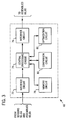
- FIGURE 3 is a general block diagram of certain functional circuits included in controller 48 when programmed to execute an optimization technique as described below.
- Controller 48 includes an interface circuit 72, a central processing circuit 74, an interface circuit 76, a memory circuit 78, a comparison circuit 80 and an optimization circuit 82.
- Interface circuit 72 which typically includes appropriate multiplexing, analog-to-digital converting and signal conditioning circuitry receives operating parameter signals from sensors 50-64 and feedback signals from actuator assemblies 66 and 68, and applies these signals to central processing circuit 74.
- interface circuit 76 which typically includes signal conditioning and valve driver circuits for operating actuator assemblies 66 and 68, receives control signals from central processing circuit 74 and commands corresponding servo movement of gates 36 and blades 42.
- Central processing circuit 74 is also linked to memory circuit 78, comparison circuit 80 and optimization circuit 82. In operation, central processing circuit 74 executes a cyclical control routine stored within memory circuit 78 for controlling operation of facility 16. As described more fully below, during certain phases of the control routine, central processing circuit 74 calls upon comparison circuit 80 to perform comparisons of the sensed operating parameters with a set of reference values for the parameters stored in memory circuit 78. These comparisons enable central processing circuit 74 to locate the set of current operating parameters in a multi-dimensional matrix (i.e. the N-dimensional virtual cam) defined by the reference values.
- a multi-dimensional matrix i.e. the N-dimensional virtual cam
- central processing circuit 74 calls upon optimization circuit 82 to perform a search of candidate gate and blade positions as summarized below. Following the search, the optimal gate and blade positions are stored in memory circuit 78 for future use when the same set of operating parameter values is encountered.
- the functional circuitry represented in FIGURE 3 may be defined by standard input/output circuitry, memory circuitry and programming code in a standard programmable logic controller, personal computer, computer workstation or the like.
- central processing circuit 74 in the form of a programmable logic controller dedicated to facility 16, is provided with resident memory for executing a main control routine.
- Comparison circuit 80 and optimization circuit 82 are configured in a portable computer system that can be selectively linked to the programmable logic controller to execute optimization of the detected set of operating parameters when desired.
- comparison and optimization circuitry may be configured in a single controller with central processing circuit 74, or may be entirely remote from facility 16 and selectively linked to central processing circuit 74 by modem or other telecommunication device.
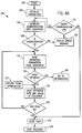
- FIGURES 4A-D illustrate exemplary control logic for performing an optimization search for a set of detected operating parameters in accordance with certain aspects of the invention.
- FIGURE 4A shows certain steps in the main control routine 100 executed by central processing circuit 74. It should be noted that details regarding the main operating routine have not been represented here for the sake of clarity and do not, per se, form a part of the present optimization technique.
- Step 102 represents the start of the cyclic control routine.
- central processing circuit 74 initializes all monitored parameters, including head, flow, power output level, tailwater level (for calculation of the submersion factor ⁇ ), trash rack head loss, and any other operating parameters needed to control operation of unit 18.
- optimization circuit 82 establishes communication with the governor module being executed by circuit 74, and at step 108 verifies that the communication link is operational. If a problem is detected in the communication link, at step 110 an error message is displayed, such as on an operator monitor (not shown) and a decision is made whether to retry the communication link at step 112. Steps 106 through 112 are particularly suited to a hardware configuration in which optimization circuit 82 is programmed in a portable or remote computer temporarily linked to central processing circuit 74.
- circuit 74 reads current values from the governor module at step 114 for all operating parameters for which performance of unit 18 is to be optimized.
- optimization is based upon a number of operating parameters in addition to the conventional dimensions of head, flow and power generation level. These include the relative submersion factor ⁇ (as an indicator or the risk of cavitation), trash rack loss, neighboring unit operating state and the relative situation of the particular unit in facility 16. These parameters are generally susceptible of influencing performance of unit 18 as follows. Relative submersion level provides an indication of the risk of cavitation within unit 18, typically reduced by increasing the submersion of turbine with respect to tailwater 26.
- the barometric pressure and water temperature are typically also sensed to permit calculation of the parameter ⁇ in a manner known in the art.
- an indication of cavitation can be provided by an acoustic sensor capable of detecting pulsations within frequency bands characteristic of cavitation. Trash rack losses may adversely affect performance by reducing the headwater pressure head.
- the operating state of neighboring units may significantly alter performance of the turbine units, such as by altering flow patterns into the upstream conduit and out of the draft tubes, particularly where a neighboring unit is entirely or substantially closed to flow.
- the immediate neighboring unit operating state is noted for each unit as either "operating" or “not operating", although depending upon the particular plant being optimized, this information may include operating state of non-adjacent units and may note additional operational levels, such as by dividing the neighboring unit operation into 5 steps of from 0 to 100% power generation level.
- the particular situation of the unit is accounted for in the optimization system by generating a unique set of optimal matrices for each unit in facility 16. The situation of the individual unit 18 in facility 16 also may have a significant impact on flow patterns into and out of the unit.
- comparison circuit 80 compares the set of operating parameters to reference levels for the parameters stored in memory circuit 78.
- anticipated ranges for head, flow, power generation level, submersion level and trash rack head loss are divided into a fixed number of reference levels, such as ten, while neighboring unit operating state is categorized into discrete classifications, such as left on/right on, left on/right off, left off/right on and left off/right off to form an N-dimensional matrix, where N is the number of operating parameters considered.
- a similar matrix is developed for each unit 18 in facility 16, effectively adding an additional layer or dimension to the overall optimization system virtual cam.
- optimization matrices are developed including at least 4 additional dimensions or operating parameters, namely, submersion level ⁇ , trash rack loss, neighboring unit operating state and physical situation of the unit in the overall facility.
- desired gate and blade positions are stored in memory circuit 78.
- comparison circuit 80 accesses the particular matrix location corresponding to the current set of operating parameters and determines whether optimal gate and blade positional settings have been determined. It should be noted that, while optimal settings may not have been determined for the particular set of parameters being evaluated, most or all of the optimal matrix locations will be populated prior to installation of the optimization portion of the control routine from model data, past performance data, index testing data or the like.
- circuit 74 progresses to block 118, where the optimization search illustrated in FIGURE 4B is executed.
- the current levels of each operating parameter must be clearly within the bounds of a particular matrix block before entry into the optimization search routine will be permitted at step 118.
- the current level of corresponding sensed parameters must be within the middle third of the range attributed to a matrix block.
- the flow rate parameter if the current level of flow through unit 18 is found to be between the matrix levels of 60 and 70 cubic meters per second, entry into the optimization search routine is permitted only if the actual flow rate is between 63.3 and 66.6 cubic meters per second. This requirement ensures that optimal settings are identified that clearly correspond to the matrix location to be populated.
- Step 120 in FIGURE 4A represents the return from the optimization routine of FIGURE 4B.
- the optimal settings for gate and blade positions are transmitted to the main governor module being executed by central processing circuit 74, which generates control signals for appropriately positioning actuator assemblies 66 and 68.
- optimization circuit 82 actually determines the difference between the optimal settings for the gate and blade positions and those settings currently stored in memory circuit 78 for the set of operating parameters under consideration, and saves these differences as corrections to the existing settings.
- circuit 82 could derive the actual value of the optimal position settings and save this value in the corresponding memory location in place of the existing settings.
- circuit 74 checks whether an exit flag has been set, such as by operator intervention, automatic interrupt or the like, and if not, returns to step 114 to continue to cycle through its control routine. If an exit flag is detected at step 124, circuit 74 proceeds to steps 126 and 128, closing all open program files and exiting the control program.
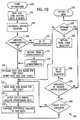
- circuit 82 enters the routine from step 118 of FIGURE 4A and reads the current gate and blade settings populating the optimal matrix location for the current set of operating parameters, as indicated at step 204.
- the matrix location is again verified.
- circuit 82 determines whether constant flow characteristic data is saved in memory circuit 78 for the current set of operating parameters. Because in the preferred embodiment, location of optimal gate and blade positional settings is determined while maintaining flow substantially constant, it is advantageous to determine combinations of actual gate and blade settings that provide constant flow for the current operating conditions prior to executing the optimization search sequence.
- circuit 82 proceeds to step 210 and performs a constant flow characteristic search routine as illustrated in FIGURE 4C and described below.
- Step 212 represents the return from the constant flow characteristic search routine.
- the constant flow characteristic data are stored in memory circuit 78 for future reference.
- the wicket gates and runner blades are moved to initial positions stored in the optimal matrix as a starting point for the optimization search.
- the gates and blades are moved to new candidate positions (but are held stationary in the initial pass through step 218).
- the optimization search progresses through gate and blade positions resulting in substantially constant flow, movement of the gates and blades in steps 216 and 218 result in some perturbation in operating parameters, particularly power generation level.
- the routine waits for a settling period during which monitored operating parameters are allowed to calm to steady state levels. Although this settling period will vary for particular installations, 2 to 5 minutes are typically sufficient for the monitored parameters to reach steady state levels.
- this settling period could be reduced or essentially eliminated by properly anticipating (e.g. modelling) transient behavior of the installation.
- Monitored data is then collected and at step 222, statistical analyses are performed on the test data, including mean and standard deviation calculations to determine whether fluctuations in parameters, particularly head, flow and power generation level have settled to within acceptable bands.
- results of the statistical analyses are compared with reference values considered to represent steady state operation. If it is determined that the system has not reached steady state operation, circuit 82 returns to step 218, but maintains the gates and blades at their current positions for an additional settling period.
- step 224 the current levels of the set of operating parameters is checked to ensure that they still correspond to the matrix location to be optimized.
- a relatively narrow band is preferred for entry into the optimization sequence, as summarized above, considerably less stringent ranges are imposed for continuation of the optimization search at step 226.
- the search sequence will terminate at step 226 only if the same parameters no longer fall within the matrix block (i.e. cross over a boundary between matrix blocks).
- circuit 82 proceeds to a point selection routine for determining whether the search should continue and, in the affirmative, determining the next candidate gate and blade settings.
- the point selection process will be described more fully with reference to FIGURE 4D.
- Step 230 of FIGURE 4B represents the return from the point selection routine.
- optimization circuit 82 determines whether an "optimum power" flag has been set in the point selection routine (see step 434 described below), indicating that the optimum (i.e.
- circuit 82 exits the optimization search at step 234, returning to step 120 of FIGURE 4A. If the flag is not detected at step 232, circuit 82 proceeds to step 218 to continue testing other candidate gate and blade settings.
- circuit 82 preferably executes a flow characteristic search routine as illustrated in FIGURE 4C.
- the search routine generally sets the runner blades at lower and upper limit positions (i.e. maximum and minimum allowable tilt) and proceeds through a series of gate positions for each blade setting to determine the interdependent flow characteristics of the gate and blade positions for the set of operating conditions under examination.
- the resulting data can then be used to identify constant flow characteristics, as shown in the curves illustrated in FIGURE 5, as a function of gate and blade positions. More detailed background on the procedure used to generate the constant flow curves is provided in U.S. Patent No. 5,402,332, issued to Kopf on March 28, 1995 and hereby incorporated into the present disclosure by reference.
- circuit 82 identifies candidate gate and blade settings for the flow rate parameter of the optimal matrix block under investigation. For example, if the virtual cam block calls for a flow rate of 60 cubic meters per second through unit 18, circuit 82 will identify candidate settings from curve 502. For flow rates of 70 or 80 cubic meters per second, curves 504 or 506, respectively, would serve as the guide for candidate positions. It should be understood that the flow rate under consideration need not correspond to any particular preset level, but will ultimately be fixed by identification of the flow rate ranges for which the virtual cam or optimal matrix is to be established.
- the present method provides data from which appropriate blade tilt and gate positions can be determined that maintain substantially constant flow through unit 18.
- the present technique utilizes the same relationships but derives the desired blade and gate positions from actual measured data.
- the method effectively determines the effect of blade tilt on flow rate (i.e. the partial derivative of flow with respect to blade tilt angle) and the effect of gate position on flow rate (i.e. the partial derivative of flow with respect to gate position) to anticipate or determine the appropriate corresponding blade and gate positions required to maintain the desired rate of flow.
- the flow characteristic search 300 begins at step 302.
- circuit 82 examines whether the lower blade position versus gate flow characteristics have been previously determined and stored in memory circuit 78. If so, the search proceeds to step 324. If not, at step 306, the blade position is set to its lower limit. With the blade thus positioned, the gates are set to their lower limit positions at step 308. It should be noted that the lower (and upper) gate and blade positions may be imposed by physical limits of the turbine unit, such as at a fully closed gate position or at the end of stroke of an actuator, or may be imposed by operational criteria, such as maximum axial shaft thrust, or a threshold point beyond which the gates may become irretrievably lodged due to water impingement forces.
- circuit 82 proceeds to step 310, where sensed parameter signals are accessed (preferably following a waiting period as described above).
- step 312 statistical analyses are performed on the parameter signals as described above with respect to step 222, and at step 314 comparisons of the statistical data (e.g. mean and standard deviation for flow, head and power generation level) are compared to acceptability bands to determine whether the system has reached steady state operation. If not, circuit 82 returns to step 308 to await steady state conditions.
- the gate position is incremented at step 316.
- a check is made at step 318 to determine whether the gate upper limit position has been reached and, if not, the search proceeds by acquiring test data for the new test setting by returning to step 310.
- circuit 82 proceeds to step 320 to determine flow characteristic data through use of a linear regression fit analysis in a manner well known in the art.
- the resulting flow characteristic data is stored at step 322, and circuit 82 proceeds to step 324 to determine flow characteristic data for the blade upper limit position.
- circuit 82 accesses existing blade upper limit flow characteristic data for the current set of operating parameter levels if such data is stored in memory circuit 78. If the data has been determined from a previous search, circuit 82 proceeds to step 344, returning to the optimization search routine. If not, the runner blades are set to their upper limit position at step 326, and the gates are set to their lower limit positions at step 328. Preferably following a settling period, parameter signals are accessed at step 330 and statistical analyses are performed on their values at step 332.
- step 334 If it is determined that the unit has reached steady state operation at step 334, the gate position is incremented at step 336 to a subsequent test position. If steady state operation has not been reached at step 334, circuit 82 returns to step 330 to again cycle through the settling period and statistical analysis steps. At step 338, a check is performed to determine whether the gate upper limit has been reached and, if not, the routine proceeds to obtain flow information for the new test position. Once the gate upper limit position is reached, the routine proceeds to step 340 where flow characteristic data is calculated for the blade upper limit test points by linear regression curve fitting. The resulting data is stored at step 342.
- test data for the gate and blade settings serves as the basis for defining candidate positions of the gates and blades resulting in substantially constant flow, as set forth in U.S. Patent No. 5,402,332 and discussed above.
- the routine returns to the optimization search routine at step 212.
- the desired flow characteristic data is determined from tests at the upper and lower blade positions and at three gate positions, including the upper and lower limit positions and one intermediate position. However, it should be understood that test data could be collected for additional intermediate positions where deemed appropriate.
- the preferred optimization search sequence proceeds through a series of candidate gate and blade positional settings to identify the those settings resulting in the maximum power output for the N-dimensional set of operating parameters for which the virtual cam matrix is to be populated.
- FIGURE 4D illustrates exemplary control logic for identifying candidate gate and blade positions and for determining whether optimal settings have been identified.
- set point selection routine 400 begins at step 402.
- circuit 82 determines whether the candidate settings most recently tested in search routine 200 were the first candidate settings. If so, no comparison data is yet available and the routine proceeds to step 406, where the gate setting is incremented. In the presently preferred embodiment, routine 200 begins with a fixed increment amount, such as 10% of the gate positional range. Based upon the new gate setting, a corresponding candidate blade position is determined at step 408 by reference to the constant flow characteristic curve for the set of operating conditions, as determined from routine 300 described above. Circuit 82 then proceeds to step 410, returning to step 230 of the optimization routine.
- step 404 the routine proceeds to step 414 where the power output level resulting from the most recent candidate settings is compared with power output levels resulting from previous candidate settings (typically the penultimate candidate settings) to determine whether the power output level has decreased. If power output has risen from the level produced from previous settings, the search proceeds to step 406 and new gate and blade candidate settings are determined, effectively continuing the search in the direction of candidate settings resulting in greater power output levels. If at step 414 it is determined that the power output level from the most recent candidate settings has decreased from the previous level, the routine advances to step 416, where the previous two output levels are examined to determine whether the decreased output level is the second consecutive decrease.
- step 406 the routine again returns to step 406 to generate and test an additional set of candidate settings in the same direction of increment. If the decrease in output level is the second consecutive decrease at step 416, the routine proceeds to step 418, indicating that the search is complete in the present direction of increment. It should be noted that steps 414, 416 and 418 permit the search to continue although a single power decrease is encountered, effectively requiring two consecutive declining power output signals before reversing the direction of the search.
- circuit 82 determines that the most recent direction of searching is not likely to locate better candidate gate and blade settings than already found, at step 420 it examines previous test points to determine whether the direction of search has already been reversed (i.e. at least two declining power output levels have resulted from settings on an opposite side of the maximum power output level thus far attained). If the result of this inquiry is negative, indicating that settings resulting in optimum power output may lie on the opposite side of the best settings thus far identified, the increment direction is reversed at step 422. At step 424, the settings are set back to the best previously identified settings, and the routine continues to step 406 to identify the next candidate settings in the new search direction.
- the candidate point selection routine after identifying gate and blade settings on either side of an optimal point, proceeds through at least an additional series of tests using a finer increment size, to provide greater resolution in identifying the optimal gate and blade settings.
- the gate increment step is reduced at steps 426, 428, 430 and 434.
- circuit 82 compares the most recent increment step size to a minimum allowable step size (such as 0.5%) to determine whether the search resolution has reached its finest level. If the result of the comparison is negative, the increment size is reduced by 1 ⁇ 2 at step 428 and the new step size is again compared to the minimum increment size at step 430.
- the increment step size is set to the minimum at step 432 and the routine proceeds to step 406 to continue to test candidate settings on either side of the current best settings using the new increment size. If at step 430 the new increment size is not less than the minimum allowable size, the routine similarly returns to step 406 to identify the optimal settings based on the new increment size. Ultimately, when the successively finer increment sizes have reached reached the minimum allowable increment size and the optimal settings are identified with the correspondingly greatest resolution, the optimum flag is set at step 434 as described above, ending the optimization search.
- the foregoing optimization technique ultimately results in population of an optimal matrix for the N-dimensional virtual cam that is subsequently referred to by the controller for setting the gate and blade positions each time the set of monitored operating parameters corresponds to the optimized matrix location. Because a particular set of operating parameters may not be encountered for a considerable time period, certain uncommon combinations of operating conditions being encountered only seasonally, yearly or during highly unusual periods (e.g. due to high rain fall amounts, runoff or the like), the matrix may not become fully populated or may take a considerable time to populate. However, once a new set of operating conditions is encountered, the optimization technique will identify the need to perform the search and proceed to identify the best settings for the new conditions.
- the optimal matrix need not include all of the additional parameters outlined above. Depending upon the particular needs and situation of a given installation, instrumentation and software for generating the optimal matrix may be added for some or all of the parameters over time. Moreover, factors other than the additional parameters identified above may be incorporated into the N-dimensional virtual cam as needed.
Landscapes
- Engineering & Computer Science (AREA)
- Chemical & Material Sciences (AREA)
- Combustion & Propulsion (AREA)
- Mechanical Engineering (AREA)
- General Engineering & Computer Science (AREA)
- Control Of Water Turbines (AREA)
- Hydraulic Turbines (AREA)
- Control Of Turbines (AREA)
- Earth Drilling (AREA)
Applications Claiming Priority (2)
| Application Number | Priority Date | Filing Date | Title |
|---|---|---|---|
| US699653 | 1996-08-19 | ||
| US08/699,653 US5754446A (en) | 1996-08-19 | 1996-08-19 | Method and apparatus for optimizing performance of a kaplan turbine |
Publications (2)
| Publication Number | Publication Date |
|---|---|
| EP0825344A1 true EP0825344A1 (fr) | 1998-02-25 |
| EP0825344B1 EP0825344B1 (fr) | 2002-05-22 |
Family
ID=24810296
Family Applications (1)
| Application Number | Title | Priority Date | Filing Date |
|---|---|---|---|
| EP97113960A Expired - Lifetime EP0825344B1 (fr) | 1996-08-19 | 1997-08-13 | Procédé d'optimisation du rendement d'une turbine kaplan |
Country Status (5)
| Country | Link |
|---|---|
| US (1) | US5754446A (fr) |
| EP (1) | EP0825344B1 (fr) |
| AT (1) | ATE217939T1 (fr) |
| DE (1) | DE69712686T2 (fr) |
| ES (1) | ES2179248T3 (fr) |
Cited By (10)
| Publication number | Priority date | Publication date | Assignee | Title |
|---|---|---|---|---|
| EP1138941A3 (fr) * | 2000-03-31 | 2006-11-02 | Reinhard Steiner | Méthode de détermination de chute pour turbines |
| ITFI20090035A1 (it) * | 2009-03-03 | 2010-09-04 | Gheorghe Turcanu | Dispositivo per la produzione di energia elettrica. |
| RU2468246C2 (ru) * | 2009-12-16 | 2012-11-27 | Анатолий Сергеевич Гольцов | Способ адаптивного управления активной мощностью гидроагрегата с поворотно-лопастной турбиной |
| CN103688048A (zh) * | 2011-05-17 | 2014-03-26 | Mj2技术公司 | 包括将水引入涡轮机的格栅组件且设计成排出由格栅阻挡的漂浮碎屑的水力发电站 |
| RU2531068C1 (ru) * | 2013-02-26 | 2014-10-20 | Анатолий Сергеевич Гольцов | Способ адаптивного управления активной мощностью и частотой гидроагрегата с поворотно-лопастной турбиной |
| EP2226501B1 (fr) | 2005-06-21 | 2016-08-10 | Senvion GmbH | Procédé et arrangement permettant de mesurer une éolienne |
| EP2307704A4 (fr) * | 2008-07-03 | 2016-10-19 | Salvatore Shifrin | Générateur de turbine hydraulique |
| CN108425791A (zh) * | 2018-02-05 | 2018-08-21 | 中国长江电力股份有限公司 | 一种调速器主配电气中位实时自动诊断及智能纠偏方法 |
| FR3129679A1 (fr) * | 2021-11-26 | 2023-06-02 | Jean Robert | Système de moteur hydraulique pour l’aménagement de petits moulins et la production d’hydroélectricité. |
| US12196169B2 (en) | 2020-08-31 | 2025-01-14 | Tmv Detections Oy | Hydro turbine with reduced cavitation |
Families Citing this family (32)
| Publication number | Priority date | Publication date | Assignee | Title |
|---|---|---|---|---|
| US5905311A (en) * | 1997-01-22 | 1999-05-18 | Voith Hydro, Inc. | Integrated hydroelectric unit |
| US5987393A (en) * | 1997-02-20 | 1999-11-16 | Abb Power T&D Company Inc. | Method of configuring a microprocessor-based relay for use in overcurrent protection |
| DE19719406C1 (de) * | 1997-05-12 | 1998-11-19 | Voith Hydro Gmbh & Co Kg | Verfahren zum Betreiben einer hydraulischen Maschine |
| US6490506B1 (en) * | 1999-05-21 | 2002-12-03 | Hydro Resource Solutions Llc | Method and apparatus for monitoring hydroelectric facility maintenance and environmental costs |
| US6441508B1 (en) * | 2000-12-12 | 2002-08-27 | Ebara International Corporation | Dual type multiple stage, hydraulic turbine power generator including reaction type turbine with adjustable blades |
| US6954713B2 (en) * | 2001-03-01 | 2005-10-11 | Fisher-Rosemount Systems, Inc. | Cavitation detection in a process plant |
| US20030218338A1 (en) * | 2002-05-23 | 2003-11-27 | O'sullivan George A. | Apparatus and method for extracting maximum power from flowing water |
| US7376472B2 (en) * | 2002-09-11 | 2008-05-20 | Fisher-Rosemount Systems, Inc. | Integrated model predictive control and optimization within a process control system |
| US6990432B1 (en) * | 2003-04-04 | 2006-01-24 | General Electric Company | Apparatus and method for performing gas turbine adjustment |
| US6975965B2 (en) * | 2004-01-12 | 2005-12-13 | International Business Machines Corporation | System and method for heuristically optimizing a large set of automated test sets |
| CA2497887A1 (fr) * | 2004-02-10 | 2005-08-10 | Jean-Francois Savard | Systeme de surveillance de porte |
| DE102006043946A1 (de) * | 2006-09-14 | 2008-03-27 | Oswald Elektromotoren Gmbh | Turbinenvorrichtung |
| US8151567B2 (en) * | 2007-05-29 | 2012-04-10 | Ford Global Technologies, Llc | Adaptive learning system and method of vane position for a variable geometry turbocharger |
| DE102007026277A1 (de) * | 2007-06-05 | 2008-12-11 | Voith Patent Gmbh | Wasserkraftanlage |
| US8581430B2 (en) | 2007-07-05 | 2013-11-12 | Salvatore Shifrin | Hydro turbine generator |
| US7831397B2 (en) * | 2008-01-18 | 2010-11-09 | The United States Of America As Represented By The Secretary Of The Army | Force beam elevator and method of use for determining absolute flow and for calibration |
| DE102009052383A1 (de) * | 2009-11-09 | 2011-05-12 | Technische Universität München | Schachtkraftwerk |
| US8314507B2 (en) | 2010-04-21 | 2012-11-20 | Kiser Hydro, Llc | Hydro unit retrofit and method of performing same |
| US20140182297A1 (en) * | 2013-01-03 | 2014-07-03 | General Electric Company | Gas turbine and method of controlling a gas turbine at part-load condition |
| FR3030640B1 (fr) * | 2014-12-22 | 2017-01-27 | Electricite De France | Systeme de pilotage de debit d'eau turbinee d'une pluralite d'usines hydroelectriques |
| US9970315B2 (en) * | 2015-02-12 | 2018-05-15 | Hamilton Sundstrand Corporation | Movable vane control system |
| CA3002149A1 (fr) * | 2015-10-22 | 2017-04-27 | Community Hydro, Llc | Systemes de production d'energie et procedes associes, composants et systemes de commande |
| DE102015222666A1 (de) * | 2015-11-17 | 2017-05-18 | Rwe Power Aktiengesellschaft | Verfahren zum Betrieb eines Laufwasserkraftwerks |
| US11018554B2 (en) * | 2016-09-19 | 2021-05-25 | Frederick Forbes Vannan, Jr. | Method of generating hydro electric energy in rivers and streams without dams and/or locks |
| JP6421850B2 (ja) * | 2016-09-20 | 2018-11-14 | ダイキン工業株式会社 | 水力発電システム |
| DE102017106718A1 (de) * | 2017-03-29 | 2018-10-04 | Voith Patent Gmbh | Hydraulische Maschine mit Vorrichtung zur Messung des Wasserstands im Saugrohr |
| DE102017116968B3 (de) * | 2017-07-27 | 2018-10-31 | Voith Patent Gmbh | Wasserkraftanlage mit einem elektrischen Antrieb zur Betätigung des Einlaufventils |
| EP3902991B1 (fr) | 2018-12-28 | 2024-05-22 | Nosmek Green Solutions, Inc. | Système avancé d'alimentation en énergie de type gravité-moment-hydro |
| SI3735529T1 (sl) | 2019-03-13 | 2023-01-31 | Natel Energy, Inc. | Hidravlična turbina |
| CN113239500B (zh) * | 2021-07-12 | 2021-09-21 | 四川大学 | 基于协方差矩阵的参考点邻域特征匹配方法 |
| PL446261A1 (pl) * | 2023-09-29 | 2024-04-22 | Przedsiębiorstwo Budowy I Eksploatacji Elektrowni Wodnych Wodel Spółka Z Ograniczoną Odpowiedzialnością | Sposób regulowania ruchu turbiny wodnej Kaplana przez komputer, zwłaszcza poza zakresem zoptymalizowanej pracy turbinowej oraz układ regulowania ruchu turbiny wodnej Kaplana poprzez komputer dla realizowania tego sposobu |
| CN119686900B (zh) * | 2024-11-12 | 2025-09-26 | 武汉理工大学 | 一种轴流转桨水轮机组桨叶-导叶协联控制方法、系统及其介质 |
Citations (5)
| Publication number | Priority date | Publication date | Assignee | Title |
|---|---|---|---|---|
| FR1099349A (fr) * | 1953-04-23 | 1955-09-02 | Voith Gmbh J M | Procédé de réglage automatique de turbines kaplan en vue d'obtenir le rendement maximum et dispositif pour la mise en pratique de ce procédé |
| GB1228445A (fr) * | 1967-04-10 | 1971-04-15 | ||
| US4794544A (en) * | 1987-03-26 | 1988-12-27 | Woodward Governor Company | Method and apparatus for automatically index testing a kaplan turbine |
| DE4220255C1 (de) * | 1992-06-23 | 1993-12-23 | Voith Gmbh J M | Verfahren zum Optimieren des Wirkunggrades eines Maschinensatzes mit einer Turbine und einem Generator |
| EP0644331A1 (fr) * | 1993-09-22 | 1995-03-22 | Sulzer - Escher Wyss AG | Procédé pour optimaliser l'efficacité d'une turbine à eau |
Family Cites Families (13)
| Publication number | Priority date | Publication date | Assignee | Title |
|---|---|---|---|---|
| DE935540C (de) * | 1953-04-24 | 1955-11-24 | Voith Gmbh J M | Verfahren zur selbsttaetigen Regelung von Kaplanturbinen auf maximalen Wirkungsgrad und Vorrichtung zur Durchfuehrung des Verfahrens |
| JPS5920280B2 (ja) * | 1974-10-29 | 1984-05-11 | 株式会社東芝 | 発電機の最適制御装置 |
| JPS54152767A (en) * | 1978-05-24 | 1979-12-01 | Hitachi Ltd | Process accomodation control method |
| CA1165441A (fr) * | 1981-04-02 | 1984-04-10 | Gilles Jasmin | Modele analogique de turbine hydraulique, regulateur de vitesse et conduite forcee |
| JPS57172286A (en) * | 1981-04-17 | 1982-10-23 | Tokyo Shibaura Electric Co | Power control device of bwr type reactor |
| SE8404441L (sv) * | 1984-09-05 | 1986-03-06 | Flygt Ab | Sett och anordning for overvakning av vattenturbiner |
| US4674279A (en) * | 1984-09-12 | 1987-06-23 | Acres International Corporation | Control system for run-of-river hydroelectric plant |
| DE3601289A1 (de) * | 1986-01-17 | 1987-07-23 | Siemens Ag | Leistungsregelung eines wassergetriebenen maschinensatzes |
| JPS62282172A (ja) * | 1986-05-12 | 1987-12-08 | Hitachi Ltd | 可変速水車発電装置 |
| US4770843A (en) * | 1987-04-08 | 1988-09-13 | Westinghouse Electric Corp. | Controlling fuel assembly stability in a boiling water reactor |
| US4994684A (en) * | 1989-01-30 | 1991-02-19 | The State Of Oregon Acting By And Through The State Board Of Higher Education On Behalf Of Oregon State University | Doubly fed generator variable speed generation control system |
| CH684207A5 (de) * | 1991-05-22 | 1994-07-29 | Escher Wyss Ag | Verfahren zur Optimierung des Wirkungsgrades einer doppelt regulierten Wasserturbine. |
| US5346359A (en) * | 1992-09-17 | 1994-09-13 | Propst Charles W | Method of adjusting a wicket gate |
-
1996
- 1996-08-19 US US08/699,653 patent/US5754446A/en not_active Expired - Fee Related
-
1997
- 1997-08-13 DE DE69712686T patent/DE69712686T2/de not_active Expired - Lifetime
- 1997-08-13 ES ES97113960T patent/ES2179248T3/es not_active Expired - Lifetime
- 1997-08-13 AT AT97113960T patent/ATE217939T1/de active
- 1997-08-13 EP EP97113960A patent/EP0825344B1/fr not_active Expired - Lifetime
Patent Citations (6)
| Publication number | Priority date | Publication date | Assignee | Title |
|---|---|---|---|---|
| FR1099349A (fr) * | 1953-04-23 | 1955-09-02 | Voith Gmbh J M | Procédé de réglage automatique de turbines kaplan en vue d'obtenir le rendement maximum et dispositif pour la mise en pratique de ce procédé |
| GB1228445A (fr) * | 1967-04-10 | 1971-04-15 | ||
| US4794544A (en) * | 1987-03-26 | 1988-12-27 | Woodward Governor Company | Method and apparatus for automatically index testing a kaplan turbine |
| DE4220255C1 (de) * | 1992-06-23 | 1993-12-23 | Voith Gmbh J M | Verfahren zum Optimieren des Wirkunggrades eines Maschinensatzes mit einer Turbine und einem Generator |
| US5402332A (en) | 1992-06-23 | 1995-03-28 | J.M. Voith Gmbh | Method for optimizing the efficiency of a set of machines comprising a turbine and a generator |
| EP0644331A1 (fr) * | 1993-09-22 | 1995-03-22 | Sulzer - Escher Wyss AG | Procédé pour optimaliser l'efficacité d'une turbine à eau |
Non-Patent Citations (3)
| Title |
|---|
| DATABASE INSPEC INSTITUTE OF ELECTRICAL ENGINEERS, STEVENAGE, GB; * |
| DATABASE INSPEC INSTITUTE OF ELECTRICAL ENGINEERS, STEVENAGE, GB; March 1992 (1992-03-01), XU ZHIDE: "Research into a single chip,mu-C based optimizing controller for Kaplan turbines.", XP002048677 * |
| J.D.STEENDAHL: "Optimizing turbine efficiency using index testing", MECHANICAL ENGINEERING, vol. 110, no. 10, 1988, N.Y.USA, pages 74 - 77, XP002048676 * |
Cited By (15)
| Publication number | Priority date | Publication date | Assignee | Title |
|---|---|---|---|---|
| EP1138941A3 (fr) * | 2000-03-31 | 2006-11-02 | Reinhard Steiner | Méthode de détermination de chute pour turbines |
| EP2226501B2 (fr) † | 2005-06-21 | 2020-12-09 | Senvion GmbH | Procédé et arrangement permettant de mesurer une éolienne |
| EP2226501B1 (fr) | 2005-06-21 | 2016-08-10 | Senvion GmbH | Procédé et arrangement permettant de mesurer une éolienne |
| EP2307704A4 (fr) * | 2008-07-03 | 2016-10-19 | Salvatore Shifrin | Générateur de turbine hydraulique |
| ITFI20090035A1 (it) * | 2009-03-03 | 2010-09-04 | Gheorghe Turcanu | Dispositivo per la produzione di energia elettrica. |
| RU2468246C2 (ru) * | 2009-12-16 | 2012-11-27 | Анатолий Сергеевич Гольцов | Способ адаптивного управления активной мощностью гидроагрегата с поворотно-лопастной турбиной |
| CN103688048A (zh) * | 2011-05-17 | 2014-03-26 | Mj2技术公司 | 包括将水引入涡轮机的格栅组件且设计成排出由格栅阻挡的漂浮碎屑的水力发电站 |
| CN103688048B (zh) * | 2011-05-17 | 2017-03-15 | Mj2技术公司 | 包括将水引入涡轮机的格栅组件且设计成排出由格栅阻挡的漂浮碎屑的水力发电站 |
| RU2531068C1 (ru) * | 2013-02-26 | 2014-10-20 | Анатолий Сергеевич Гольцов | Способ адаптивного управления активной мощностью и частотой гидроагрегата с поворотно-лопастной турбиной |
| CN108425791A (zh) * | 2018-02-05 | 2018-08-21 | 中国长江电力股份有限公司 | 一种调速器主配电气中位实时自动诊断及智能纠偏方法 |
| CN111365187A (zh) * | 2018-02-05 | 2020-07-03 | 中国长江电力股份有限公司 | 一种调速器主配电气中位实时自动诊断及智能纠偏方法 |
| CN111365187B (zh) * | 2018-02-05 | 2021-09-17 | 中国长江电力股份有限公司 | 一种调速器主配电气中位实时自动诊断及智能纠偏方法 |
| US12196169B2 (en) | 2020-08-31 | 2025-01-14 | Tmv Detections Oy | Hydro turbine with reduced cavitation |
| US12416284B2 (en) | 2020-08-31 | 2025-09-16 | Tmv Detections Oy | Measurement arrangement for hydro turbine |
| FR3129679A1 (fr) * | 2021-11-26 | 2023-06-02 | Jean Robert | Système de moteur hydraulique pour l’aménagement de petits moulins et la production d’hydroélectricité. |
Also Published As
| Publication number | Publication date |
|---|---|
| ES2179248T3 (es) | 2003-01-16 |
| US5754446A (en) | 1998-05-19 |
| ATE217939T1 (de) | 2002-06-15 |
| DE69712686D1 (de) | 2002-06-27 |
| DE69712686T2 (de) | 2004-02-19 |
| EP0825344B1 (fr) | 2002-05-22 |
Similar Documents
| Publication | Publication Date | Title |
|---|---|---|
| US5754446A (en) | Method and apparatus for optimizing performance of a kaplan turbine | |
| US6490506B1 (en) | Method and apparatus for monitoring hydroelectric facility maintenance and environmental costs | |
| Zhao et al. | On the use of artificial neural networks for condition monitoring of pump-turbines with extended operation | |
| US6850821B2 (en) | Control system for a wind power plant | |
| US6865511B2 (en) | Process and device for evaluating the performance of a process control system | |
| US4794544A (en) | Method and apparatus for automatically index testing a kaplan turbine | |
| US6357389B1 (en) | Control system for enhancing fish survivability in a hydroelectric power generation installation | |
| Liu et al. | A selected literature review of efficiency improvements in hydraulic turbines | |
| CN1064112C (zh) | 带一水轮机和一发电机的机组效率的优化方法 | |
| CN109670400A (zh) | 一种水电机组开机过程稳定性状态评价方法 | |
| US5953227A (en) | Method and apparatus for monitoring hydroelectric facility performance costs | |
| US6269287B1 (en) | Method and apparatus for monitoring a hydroelectric facility trash rack and optimizing performance | |
| US5800077A (en) | Method and apparatus for monitoring a hydroelectric facility trash rack | |
| CN118709060A (zh) | 一种基于大数据分析汽轮机的故障诊断系统及方法 | |
| CN121088571A (zh) | 一种风力发电变桨载荷抑制方法及系统 | |
| CN113567164B (zh) | 一种风电场技术改造需求系统性评估预测方法 | |
| CN119712398A (zh) | 水轮机的实时监测和控制方法、系统、设备及介质 | |
| CN120029074A (zh) | 一种汽轮机功频电液控制系统参数的优化方法 | |
| von Locquenghien et al. | Model test with sensor equipped Francis runner for Part Load Operation | |
| Zhao et al. | A novel condition monitoring methodology based on neural network of pump-turbines with extended operating range | |
| CN117189568A (zh) | 一种水轮机调速器压力油泵健康运行状态识别方法及系统 | |
| CN117212027A (zh) | 水轮机极低水头运行监测方法及系统 | |
| CN120232401B (zh) | 一种轻浪水环境的水上浮动监测工作平台及水文监测方法 | |
| CN119802254B (zh) | 一种防止电厂抽汽逆止阀模拟量反馈超温老化的装置 | |
| CN119266946A (zh) | 一种油压稳定且可调的给水泵汽轮机润滑油系统 |
Legal Events
| Date | Code | Title | Description |
|---|---|---|---|
| PUAI | Public reference made under article 153(3) epc to a published international application that has entered the european phase |
Free format text: ORIGINAL CODE: 0009012 |
|
| AK | Designated contracting states |
Kind code of ref document: A1 Designated state(s): AT DE ES FR SE |
|
| 17P | Request for examination filed |
Effective date: 19980505 |
|
| AKX | Designation fees paid |
Free format text: AT DE ES FR SE |
|
| RBV | Designated contracting states (corrected) |
Designated state(s): AT DE ES FR SE |
|
| 17Q | First examination report despatched |
Effective date: 19991027 |
|
| GRAG | Despatch of communication of intention to grant |
Free format text: ORIGINAL CODE: EPIDOS AGRA |
|
| RTI1 | Title (correction) |
Free format text: METHOD FOR OPTIMIZING PERFORMANCE OF A KAPLAN TURBINE |
|
| GRAG | Despatch of communication of intention to grant |
Free format text: ORIGINAL CODE: EPIDOS AGRA |
|
| GRAH | Despatch of communication of intention to grant a patent |
Free format text: ORIGINAL CODE: EPIDOS IGRA |
|
| GRAH | Despatch of communication of intention to grant a patent |
Free format text: ORIGINAL CODE: EPIDOS IGRA |
|
| GRAA | (expected) grant |
Free format text: ORIGINAL CODE: 0009210 |
|
| REF | Corresponds to: |
Ref document number: 217939 Country of ref document: AT Date of ref document: 20020615 Kind code of ref document: T |
|
| REF | Corresponds to: |
Ref document number: 69712686 Country of ref document: DE Date of ref document: 20020627 |
|
| ET | Fr: translation filed | ||
| REG | Reference to a national code |
Ref country code: ES Ref legal event code: FG2A Ref document number: 2179248 Country of ref document: ES Kind code of ref document: T3 |
|
| PLBE | No opposition filed within time limit |
Free format text: ORIGINAL CODE: 0009261 |
|
| STAA | Information on the status of an ep patent application or granted ep patent |
Free format text: STATUS: NO OPPOSITION FILED WITHIN TIME LIMIT |
|
| 26N | No opposition filed |
Effective date: 20030225 |
|
| REG | Reference to a national code |
Ref country code: FR Ref legal event code: PLFP Year of fee payment: 20 |
|
| PGFP | Annual fee paid to national office [announced via postgrant information from national office to epo] |
Ref country code: DE Payment date: 20160822 Year of fee payment: 20 |
|
| PGFP | Annual fee paid to national office [announced via postgrant information from national office to epo] |
Ref country code: AT Payment date: 20160822 Year of fee payment: 20 Ref country code: SE Payment date: 20160819 Year of fee payment: 20 Ref country code: FR Payment date: 20160822 Year of fee payment: 20 |
|
| PGFP | Annual fee paid to national office [announced via postgrant information from national office to epo] |
Ref country code: ES Payment date: 20160810 Year of fee payment: 20 |
|
| REG | Reference to a national code |
Ref country code: DE Ref legal event code: R071 Ref document number: 69712686 Country of ref document: DE |
|
| REG | Reference to a national code |
Ref country code: SE Ref legal event code: EUG |
|
| REG | Reference to a national code |
Ref country code: AT Ref legal event code: MK07 Ref document number: 217939 Country of ref document: AT Kind code of ref document: T Effective date: 20170813 |
|
| REG | Reference to a national code |
Ref country code: ES Ref legal event code: FD2A Effective date: 20180508 |
|
| PG25 | Lapsed in a contracting state [announced via postgrant information from national office to epo] |
Ref country code: ES Free format text: LAPSE BECAUSE OF EXPIRATION OF PROTECTION Effective date: 20170814 |