EP0825383A2 - Plaque de grille - Google Patents
Plaque de grille Download PDFInfo
- Publication number
- EP0825383A2 EP0825383A2 EP97111615A EP97111615A EP0825383A2 EP 0825383 A2 EP0825383 A2 EP 0825383A2 EP 97111615 A EP97111615 A EP 97111615A EP 97111615 A EP97111615 A EP 97111615A EP 0825383 A2 EP0825383 A2 EP 0825383A2
- Authority
- EP
- European Patent Office
- Prior art keywords
- grate
- cover segment
- plate
- base body
- grate plate
- Prior art date
- Legal status (The legal status is an assumption and is not a legal conclusion. Google has not performed a legal analysis and makes no representation as to the accuracy of the status listed.)
- Granted
Links
- 239000002826 coolant Substances 0.000 claims abstract description 23
- XLYOFNOQVPJJNP-UHFFFAOYSA-N water Substances O XLYOFNOQVPJJNP-UHFFFAOYSA-N 0.000 claims abstract description 8
- 239000000463 material Substances 0.000 claims description 12
- 229910000831 Steel Inorganic materials 0.000 claims description 3
- 239000010959 steel Substances 0.000 claims description 3
- 238000004056 waste incineration Methods 0.000 claims description 3
- 238000009835 boiling Methods 0.000 abstract description 2
- 238000002485 combustion reaction Methods 0.000 description 10
- 238000010304 firing Methods 0.000 description 6
- 239000002699 waste material Substances 0.000 description 5
- 238000001816 cooling Methods 0.000 description 2
- JEIPFZHSYJVQDO-UHFFFAOYSA-N iron(III) oxide Inorganic materials O=[Fe]O[Fe]=O JEIPFZHSYJVQDO-UHFFFAOYSA-N 0.000 description 2
- UGFAIRIUMAVXCW-UHFFFAOYSA-N Carbon monoxide Chemical compound [O+]#[C-] UGFAIRIUMAVXCW-UHFFFAOYSA-N 0.000 description 1
- 238000005299 abrasion Methods 0.000 description 1
- 238000013019 agitation Methods 0.000 description 1
- 239000000498 cooling water Substances 0.000 description 1
- 238000007872 degassing Methods 0.000 description 1
- 239000010791 domestic waste Substances 0.000 description 1
- 238000001035 drying Methods 0.000 description 1
- 239000003546 flue gas Substances 0.000 description 1
- 239000000446 fuel Substances 0.000 description 1
- 238000002309 gasification Methods 0.000 description 1
- 239000011261 inert gas Substances 0.000 description 1
- 239000007788 liquid Substances 0.000 description 1
- 239000002184 metal Substances 0.000 description 1
- 238000002156 mixing Methods 0.000 description 1
- 238000005192 partition Methods 0.000 description 1
- 239000007787 solid Substances 0.000 description 1
Images



Classifications
-
- F—MECHANICAL ENGINEERING; LIGHTING; HEATING; WEAPONS; BLASTING
- F23—COMBUSTION APPARATUS; COMBUSTION PROCESSES
- F23H—GRATES; CLEANING OR RAKING GRATES
- F23H3/00—Grates with hollow bars
- F23H3/02—Grates with hollow bars internally cooled
-
- F—MECHANICAL ENGINEERING; LIGHTING; HEATING; WEAPONS; BLASTING
- F23—COMBUSTION APPARATUS; COMBUSTION PROCESSES
- F23H—GRATES; CLEANING OR RAKING GRATES
- F23H17/00—Details of grates
- F23H17/12—Fire-bars
-
- F—MECHANICAL ENGINEERING; LIGHTING; HEATING; WEAPONS; BLASTING
- F23—COMBUSTION APPARATUS; COMBUSTION PROCESSES
- F23H—GRATES; CLEANING OR RAKING GRATES
- F23H7/00—Inclined or stepped grates
- F23H7/06—Inclined or stepped grates with movable bars disposed parallel to direction of fuel feeding
- F23H7/08—Inclined or stepped grates with movable bars disposed parallel to direction of fuel feeding reciprocating along their axes
-
- F—MECHANICAL ENGINEERING; LIGHTING; HEATING; WEAPONS; BLASTING
- F23—COMBUSTION APPARATUS; COMBUSTION PROCESSES
- F23H—GRATES; CLEANING OR RAKING GRATES
- F23H2900/00—Special features of combustion grates
- F23H2900/03021—Liquid cooled grates
-
- F—MECHANICAL ENGINEERING; LIGHTING; HEATING; WEAPONS; BLASTING
- F23—COMBUSTION APPARATUS; COMBUSTION PROCESSES
- F23H—GRATES; CLEANING OR RAKING GRATES
- F23H2900/00—Special features of combustion grates
- F23H2900/17002—Detachable or removable worn-out parts
Definitions
- the invention relates to a grate plate for feed grates, in particular for feed grates from Waste incineration plants, the feed grate consisting of several mutually movable, there are stepped grate plate rows and the grate plate extends over the entire width of the feed grate or the rust track and this through water or with one opposite Water is cooled by high-boiling coolant.
- feed grids are by transversely to the direction of transport of the material extending, gradually overlapping rows of grate plates or grate bars. Every second row of grate plates or grate bars usually leads to the transport of the firing material a thrust movement caused by a drive device.
- the waste becomes one transported and the other mixed and stirred.
- the waste on the feed grate it is dried, preheated, degassed and gasified one after the other and burned out the combustible.
- EP 0 621 449 B1 has disclosed a water-cooled grate plate which overlaps extends the entire width of the combustion grate or grate track, which is made of sheet metal, forms a hollow body with top and bottom and at least on one side of the bottom a connection piece and on the other side at least one discharge pipe for the Has supply and discharge of a liquid medium flowing through them for their temperature control.
- a disadvantage of the known grate plate has been shown that when a replacement is required a grate plate, z. B. by mechanical abrasion, by thermal or Corrosive wear or damage, one complete grate plate replaced must become. Due to the grate plates, some of which are up to 3.0 m wide, problems arise with the Removing and installing such grate plates due to their high weight and bulk. It is also not justifiable from an economic point of view, a partially worn grate plate to be exchanged completely.
- the object of the present invention is to provide a grate plate, the aforementioned Avoids disadvantages.
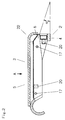
- FIG. 1 shows sections of the schematic longitudinal section through one of several rows of grate plates 26 formed grate 25 for the combustion of waste.
- the feed grate 25 is usually slightly inclined in the transport direction of the firing material.
- Transport and mixing or agitation of the firing material is due to the pushing movement of mechanical or hydraulic drive devices driven grate plate carrier 28 or rows of grate plates 26 causes, usually every second row of grate plates 26 is driven and the intermediate rows of grate plates 26 are stationary.
- Take over the grate plate carrier 28 the function of supporting the grate plates 1 and also the pushing movement.
- the feeder The primary combustion air to the firing material comes through the below the feed grate 25 arranged air zones 27 and the nozzle-shaped in the grate plates 1 Air gaps 6, the air zones 27 in the longitudinal direction and possibly also in the transverse direction of the feed grate 25 are divided into several zones.
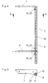
- grate plate 1 according to the invention, which extends over the entire width of the feed grate 25 or a grate track of a multi-track feed grate 25 and the from a base body 2 and, depending on the width of the grate plate 1, from one or more cover segments 3 exists.
- the base body 2 forms the grate plate base 4, which on the following, underlying row of grate plates 26 rests and forms the cover segment (s) 3 form the grate plate body 5, the front end of which closes with the grate plate head 22.
- the grate plate 1 enables the partial replacement of cover segments 3, which are more exposed to the firing material than the base body 2 and are therefore more worn or damaged.
- the base body 2 consists of two side plates 7, one bottom plate 8 arranged therebetween, depending on the width, with one or more if necessary Intermediate plates 9 and at least one, flowed through by a coolant and between the Side plates 7 or, in the case of existing intermediate plates 9, also between side plates 7 and intermediate plates 9 and between the intermediate plates 9 arranged hollow profiles 10 is formed.
- intermediate plates 9 these are preferably across the width of the base body 2 evenly distributed.
- the hollow profile 10 is preferably formed as a rectangular hollow profile and is in the longitudinal direction Grate plate 1 (i.e. in the direction of transport) seen opposite the front edge of the back plate 14 and lower plate 15 (grate plate head 22) of the cover segment 3 set back in such a way that between the lower plate 15 and the upper edge of the hollow profile 10, a nozzle-shaped air gap 6 is formed for supplying primary combustion air into the firing material.
- the nozzle-shaped Air gap 6 is thus formed by base body 2 and cover segment 3 and extends across the width of the grate plate 1, interrupted only if necessary by intermediate plates 9.
- the front edge of the base plate 8 is also opposite the front edge of the back plate 14 set back to the main load of the Brennguttransportes to the front to shift the back plate 14.
- a grate plate 1 extends depending on the width of the grate plate 1 between two side plates 7 or between side plates 7 and Intermediate plates 9 and possibly between the intermediate plates 9 of a base body 2.
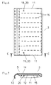
- the cover segment 3 consists of two side plates 11, support element 13 arranged between them, Back and bottom plate 14, 15.
- Side plates 11, support element 13, back and bottom plate 14, 15 form one of a coolant, e.g. B. water, flowed through cavity 12, which with several, a labyrinth-forming partition plates 16 is provided.
- a coolant e.g. B. water
- the cover segment 3 and the base body 2 each have separate coolant inflows and drains 18, 19 which are arranged to the side of the air zones 27. At least one each Inflow 18 is on one side of the lower plate 15 of the cover segment 3 and the hollow profile 10 of the base body 2 and at least one drain 19 is on the other side of the lower plate 15 of the cover segment 3 and the hollow profiles 10 of the base body 2 are arranged. Inlets and outlets 18, 19 are equipped with devices 20, for. B. a connecting piece for connection formed by connecting lines, not shown. For grate plates 1 with several in a row arranged hollow profiles 10 and cover segments 3 is the coolant drain 19th through a connecting line 21 to the coolant inflow 18 of the adjacent hollow profile 10 or cover segment 3 connected.
- the lower plate 15 is angled in the area of the grate plate head 22 such that the middle Outflow angle ⁇ of the nozzle-shaped air gap 6 is at an angle to the horizontal from 10 - 60 °.
- Base body 2 and cover segment 3 are preferably the same from steel sheets and profiles Made of material and welded in each case.
- the base plate 8 is opposite the back plate 14 formed from more wear-resistant material.
- the cover segment (s) 3 are with their side plates 11 by at least two Connecting means 17, e.g. B. screw connection, with the side plates 7 and intermediate plates 9th of the base body 2 connected.
- the air gap 6 can be arranged in parallel according to FIG. 8 by inserting a guide plate 23 Air gap walls should be formed. A divergent air gap 6, if necessary, is also through appropriate design of the lower plate 15 and the guide plate 23 possible (not shown).
- the upper part of the hollow profile 10 is designed in accordance with the contour of the guide plate 23 or in another desired shape be (not shown).
Landscapes
- Engineering & Computer Science (AREA)
- Chemical & Material Sciences (AREA)
- Combustion & Propulsion (AREA)
- Mechanical Engineering (AREA)
- General Engineering & Computer Science (AREA)
- Incineration Of Waste (AREA)
- Polishing Bodies And Polishing Tools (AREA)
- Laminated Bodies (AREA)
- Table Devices Or Equipment (AREA)
- Non-Silver Salt Photosensitive Materials And Non-Silver Salt Photography (AREA)
Applications Claiming Priority (2)
| Application Number | Priority Date | Filing Date | Title |
|---|---|---|---|
| DE19632316 | 1996-08-10 | ||
| DE19632316A DE19632316C1 (de) | 1996-08-10 | 1996-08-10 | Rostplatte |
Publications (3)
| Publication Number | Publication Date |
|---|---|
| EP0825383A2 true EP0825383A2 (fr) | 1998-02-25 |
| EP0825383A3 EP0825383A3 (fr) | 1998-09-16 |
| EP0825383B1 EP0825383B1 (fr) | 2002-01-23 |
Family
ID=7802317
Family Applications (1)
| Application Number | Title | Priority Date | Filing Date |
|---|---|---|---|
| EP97111615A Expired - Lifetime EP0825383B1 (fr) | 1996-08-10 | 1997-07-09 | Plaque de grille |
Country Status (7)
| Country | Link |
|---|---|
| EP (1) | EP0825383B1 (fr) |
| AT (1) | ATE212429T1 (fr) |
| CZ (1) | CZ291546B6 (fr) |
| DE (2) | DE19632316C1 (fr) |
| HU (1) | HU218993B (fr) |
| PL (1) | PL321534A1 (fr) |
| SK (1) | SK106697A3 (fr) |
Cited By (4)
| Publication number | Priority date | Publication date | Assignee | Title |
|---|---|---|---|---|
| DE19851471A1 (de) * | 1998-11-09 | 2000-05-11 | Mitteldeutsche Feuerungs Und U | Durchfallarmer Vorschubrostbelag |
| DE19912944C1 (de) * | 1999-03-23 | 2000-07-27 | Didier Werke Ag | Rostwangen-Abdichtkörper |
| FR2894012A1 (fr) * | 2005-11-28 | 2007-06-01 | Cometal France Sarl | Barreau pour grille de four d'incineration |
| CN112610955A (zh) * | 2020-12-18 | 2021-04-06 | 上海康恒环境股份有限公司 | 一种焚烧炉炉排组合式炉排条结构 |
Families Citing this family (4)
| Publication number | Priority date | Publication date | Assignee | Title |
|---|---|---|---|---|
| DE19753981C2 (de) * | 1997-12-05 | 2000-04-06 | Alstom Energy Syst Gmbh | Flüssigkeitsgekühlte Rostplatte |
| EP0924464A1 (fr) * | 1997-12-19 | 1999-06-23 | KOCH, Theodor | Grille d'une installation de combustion et méthode pour son refroidissement |
| DE19860552C2 (de) * | 1998-12-22 | 2001-02-08 | Mannesmann Ag | Kühlbarer Verbrennungsrost |
| DE19860553C2 (de) * | 1998-12-22 | 2001-03-29 | Mannesmann Ag | Flüssigkeitsgekühlter Verbrennungsrost |
Citations (1)
| Publication number | Priority date | Publication date | Assignee | Title |
|---|---|---|---|---|
| EP0621449B1 (fr) | 1993-04-20 | 1995-08-09 | Doikos Investments Ltd | Procédé pour la combustion de déchets sur une grille de combustion ainsi qu'une grille de combustion pour la mise en oeuvre du procédé et barreau pour la fabrication d'une telle grille |
Family Cites Families (3)
| Publication number | Priority date | Publication date | Assignee | Title |
|---|---|---|---|---|
| DE2833255A1 (de) * | 1978-07-28 | 1980-02-07 | Pauli Gmbh Waermetechnik | Luftgekuehlter roststab |
| IT1235900B (it) * | 1985-10-11 | 1992-12-02 | Vaifro Vittorio Bonomelli | Griglia di combustione a gradini mobili per combustibili solidi in particolare rifiuti solidi urbani e assimilabili |
| FR2694376B1 (fr) * | 1992-07-31 | 1994-09-30 | A3C Metal | Barreau pour grille d'incinération d'ordures ménagères. |
-
1996
- 1996-08-10 DE DE19632316A patent/DE19632316C1/de not_active Expired - Fee Related
-
1997
- 1997-06-13 HU HU9701047A patent/HU218993B/hu not_active IP Right Cessation
- 1997-07-09 AT AT97111615T patent/ATE212429T1/de not_active IP Right Cessation
- 1997-07-09 DE DE59706162T patent/DE59706162D1/de not_active Expired - Fee Related
- 1997-07-09 EP EP97111615A patent/EP0825383B1/fr not_active Expired - Lifetime
- 1997-08-06 SK SK1066-97A patent/SK106697A3/sk unknown
- 1997-08-06 CZ CZ19972492A patent/CZ291546B6/cs not_active IP Right Cessation
- 1997-08-08 PL PL97321534A patent/PL321534A1/xx unknown
Patent Citations (1)
| Publication number | Priority date | Publication date | Assignee | Title |
|---|---|---|---|---|
| EP0621449B1 (fr) | 1993-04-20 | 1995-08-09 | Doikos Investments Ltd | Procédé pour la combustion de déchets sur une grille de combustion ainsi qu'une grille de combustion pour la mise en oeuvre du procédé et barreau pour la fabrication d'une telle grille |
Cited By (4)
| Publication number | Priority date | Publication date | Assignee | Title |
|---|---|---|---|---|
| DE19851471A1 (de) * | 1998-11-09 | 2000-05-11 | Mitteldeutsche Feuerungs Und U | Durchfallarmer Vorschubrostbelag |
| DE19912944C1 (de) * | 1999-03-23 | 2000-07-27 | Didier Werke Ag | Rostwangen-Abdichtkörper |
| FR2894012A1 (fr) * | 2005-11-28 | 2007-06-01 | Cometal France Sarl | Barreau pour grille de four d'incineration |
| CN112610955A (zh) * | 2020-12-18 | 2021-04-06 | 上海康恒环境股份有限公司 | 一种焚烧炉炉排组合式炉排条结构 |
Also Published As
| Publication number | Publication date |
|---|---|
| CZ291546B6 (cs) | 2003-04-16 |
| HUP9701047A3 (en) | 1999-09-28 |
| SK106697A3 (en) | 1998-06-03 |
| EP0825383A3 (fr) | 1998-09-16 |
| HU9701047D0 (en) | 1997-08-28 |
| ATE212429T1 (de) | 2002-02-15 |
| EP0825383B1 (fr) | 2002-01-23 |
| DE59706162D1 (de) | 2002-03-14 |
| CZ249297A3 (cs) | 1998-03-18 |
| PL321534A1 (en) | 1998-02-16 |
| DE19632316C1 (de) | 1997-09-04 |
| HUP9701047A2 (hu) | 1998-04-28 |
| HU218993B (hu) | 2001-01-29 |
Similar Documents
| Publication | Publication Date | Title |
|---|---|---|
| EP0757206B1 (fr) | Grille pour un foyer | |
| DE69305095T2 (de) | Kühler zum kühlen von schüttgut | |
| EP0844438B1 (fr) | Grille pour un foyer | |
| EP0954722B1 (fr) | Grille de combustion a refroidissement par eau | |
| EP0921354B1 (fr) | Plaque de grille refroidie par liquide | |
| DD232539B5 (de) | Rostbodenelement zum Aufbau einer Rostflaeche | |
| DE2835854C2 (de) | Schlackenrinne für Hochöfen | |
| EP0499912B1 (fr) | Barreau de grille et grille pour installations de combustion | |
| EP0713056B1 (fr) | Barreau de grille avec dispositif de refroidissement | |
| EP0165432B1 (fr) | Four, notamment pour la combustion des ordures, du charbon, du bois et des déchets industriels | |
| EP0825383B1 (fr) | Plaque de grille | |
| DE2604611C2 (de) | Vorschubstufen-Rostkühler | |
| DE19613507C1 (de) | Rostplatte | |
| EP0060239B1 (fr) | Cheval de coulée pour métal en fusion | |
| WO1999032831A1 (fr) | Barreau de grille pour grille de combustion et procede pour son refroidissement | |
| DE19721206A1 (de) | Vorrichtung zur Entnahme und Kühlung von Bettasche aus einer Wirbelschichtfeuerung | |
| EP2306086B1 (fr) | Barreau de grille | |
| DE69505016T2 (de) | Brennstoffverbrennungs- und förderrost für verbrennungsanlagen, insbesondere müllverbrennungsanlagen | |
| EP0288597B1 (fr) | Feu à grille pour l'incinération des déchets | |
| DE3926125C1 (en) | Incinerator air cooled grate with transverse supports - has several grate bars bolted into groups, clad by wear-resistant plates on top and bottom | |
| DE102008056468B3 (de) | Rostplattenschubrost für Verbrennungsanlagen | |
| DE4026587C1 (fr) | ||
| DE19537904A1 (de) | Rostplatte | |
| DE3813441C2 (fr) | ||
| EP0981021A1 (fr) | Grille pour incinérateurs |
Legal Events
| Date | Code | Title | Description |
|---|---|---|---|
| PUAI | Public reference made under article 153(3) epc to a published international application that has entered the european phase |
Free format text: ORIGINAL CODE: 0009012 |
|
| AK | Designated contracting states |
Kind code of ref document: A2 Designated state(s): AT BE DE DK ES GR IT LU NL PT |
|
| AX | Request for extension of the european patent |
Free format text: AL;LT;LV;RO;SI PAYMENT 970716 |
|
| PUAL | Search report despatched |
Free format text: ORIGINAL CODE: 0009013 |
|
| AK | Designated contracting states |
Kind code of ref document: A3 Designated state(s): AT BE CH DE DK ES FI FR GB GR IE IT LI LU MC NL PT SE |
|
| AX | Request for extension of the european patent |
Free format text: AL;LT;LV;RO;SI PAYMENT 970716 |
|
| RAP1 | Party data changed (applicant data changed or rights of an application transferred) |
Owner name: ALSTOM ENERGY SYSTEMS GMBH |
|
| 17P | Request for examination filed |
Effective date: 19981002 |
|
| AKX | Designation fees paid |
Free format text: AT BE DE ES GR IT LU NL PT |
|
| AXX | Extension fees paid |
Free format text: SI PAYMENT 19970716 |
|
| RBV | Designated contracting states (corrected) |
Designated state(s): AT BE DE ES GR IT LU NL PT |
|
| RBV | Designated contracting states (corrected) |
Designated state(s): AT BE DE DK ES GR IT LU NL PT |
|
| GRAG | Despatch of communication of intention to grant |
Free format text: ORIGINAL CODE: EPIDOS AGRA |
|
| 17Q | First examination report despatched |
Effective date: 20010215 |
|
| GRAG | Despatch of communication of intention to grant |
Free format text: ORIGINAL CODE: EPIDOS AGRA |
|
| GRAH | Despatch of communication of intention to grant a patent |
Free format text: ORIGINAL CODE: EPIDOS IGRA |
|
| RAP1 | Party data changed (applicant data changed or rights of an application transferred) |
Owner name: ALSTOM POWER BOILER GMBH |
|
| GRAH | Despatch of communication of intention to grant a patent |
Free format text: ORIGINAL CODE: EPIDOS IGRA |
|
| GRAA | (expected) grant |
Free format text: ORIGINAL CODE: 0009210 |
|
| AK | Designated contracting states |
Kind code of ref document: B1 Designated state(s): AT BE DE DK ES GR IT LU NL PT |
|
| AX | Request for extension of the european patent |
Free format text: SI PAYMENT 19970716 |
|
| PG25 | Lapsed in a contracting state [announced via postgrant information from national office to epo] |
Ref country code: NL Free format text: LAPSE BECAUSE OF FAILURE TO SUBMIT A TRANSLATION OF THE DESCRIPTION OR TO PAY THE FEE WITHIN THE PRESCRIBED TIME-LIMIT Effective date: 20020123 Ref country code: IT Free format text: LAPSE BECAUSE OF FAILURE TO SUBMIT A TRANSLATION OF THE DESCRIPTION OR TO PAY THE FEE WITHIN THE PRESCRIBED TIME-LIMIT;WARNING: LAPSES OF ITALIAN PATENTS WITH EFFECTIVE DATE BEFORE 2007 MAY HAVE OCCURRED AT ANY TIME BEFORE 2007. THE CORRECT EFFECTIVE DATE MAY BE DIFFERENT FROM THE ONE RECORDED. Effective date: 20020123 Ref country code: GR Free format text: LAPSE BECAUSE OF FAILURE TO SUBMIT A TRANSLATION OF THE DESCRIPTION OR TO PAY THE FEE WITHIN THE PRESCRIBED TIME-LIMIT Effective date: 20020123 |
|
| REF | Corresponds to: |
Ref document number: 212429 Country of ref document: AT Date of ref document: 20020215 Kind code of ref document: T |
|
| REF | Corresponds to: |
Ref document number: 59706162 Country of ref document: DE Date of ref document: 20020314 |
|
| PG25 | Lapsed in a contracting state [announced via postgrant information from national office to epo] |
Ref country code: PT Free format text: LAPSE BECAUSE OF FAILURE TO SUBMIT A TRANSLATION OF THE DESCRIPTION OR TO PAY THE FEE WITHIN THE PRESCRIBED TIME-LIMIT Effective date: 20020423 Ref country code: DK Free format text: LAPSE BECAUSE OF FAILURE TO SUBMIT A TRANSLATION OF THE DESCRIPTION OR TO PAY THE FEE WITHIN THE PRESCRIBED TIME-LIMIT Effective date: 20020423 |
|
| NLV1 | Nl: lapsed or annulled due to failure to fulfill the requirements of art. 29p and 29m of the patents act | ||
| PG25 | Lapsed in a contracting state [announced via postgrant information from national office to epo] |
Ref country code: LU Free format text: LAPSE BECAUSE OF NON-PAYMENT OF DUE FEES Effective date: 20020709 |
|
| PG25 | Lapsed in a contracting state [announced via postgrant information from national office to epo] |
Ref country code: ES Free format text: LAPSE BECAUSE OF FAILURE TO SUBMIT A TRANSLATION OF THE DESCRIPTION OR TO PAY THE FEE WITHIN THE PRESCRIBED TIME-LIMIT Effective date: 20020730 |
|
| PG25 | Lapsed in a contracting state [announced via postgrant information from national office to epo] |
Ref country code: BE Free format text: LAPSE BECAUSE OF NON-PAYMENT OF DUE FEES Effective date: 20020731 |
|
| PGFP | Annual fee paid to national office [announced via postgrant information from national office to epo] |
Ref country code: AT Payment date: 20020731 Year of fee payment: 6 |
|
| PGFP | Annual fee paid to national office [announced via postgrant information from national office to epo] |
Ref country code: DE Payment date: 20020802 Year of fee payment: 6 |
|
| PLBE | No opposition filed within time limit |
Free format text: ORIGINAL CODE: 0009261 |
|
| STAA | Information on the status of an ep patent application or granted ep patent |
Free format text: STATUS: NO OPPOSITION FILED WITHIN TIME LIMIT |
|
| 26N | No opposition filed | ||
| BERE | Be: lapsed |
Owner name: *ALSTOM POWER BOILER G.M.B.H. Effective date: 20020731 |
|
| PG25 | Lapsed in a contracting state [announced via postgrant information from national office to epo] |
Ref country code: AT Free format text: LAPSE BECAUSE OF NON-PAYMENT OF DUE FEES Effective date: 20030709 |
|
| PG25 | Lapsed in a contracting state [announced via postgrant information from national office to epo] |
Ref country code: DE Free format text: LAPSE BECAUSE OF NON-PAYMENT OF DUE FEES Effective date: 20040203 |