EP0825403A2 - Labortrockner - Google Patents
Labortrockner Download PDFInfo
- Publication number
- EP0825403A2 EP0825403A2 EP97112127A EP97112127A EP0825403A2 EP 0825403 A2 EP0825403 A2 EP 0825403A2 EP 97112127 A EP97112127 A EP 97112127A EP 97112127 A EP97112127 A EP 97112127A EP 0825403 A2 EP0825403 A2 EP 0825403A2
- Authority
- EP
- European Patent Office
- Prior art keywords
- convection
- room
- laboratory dryer
- drying
- dryer according
- Prior art date
- Legal status (The legal status is an assumption and is not a legal conclusion. Google has not performed a legal analysis and makes no representation as to the accuracy of the status listed.)
- Withdrawn
Links
- 238000001035 drying Methods 0.000 claims abstract description 55
- 239000007789 gas Substances 0.000 claims abstract description 26
- 239000003973 paint Substances 0.000 claims abstract description 9
- 238000000034 method Methods 0.000 claims abstract description 8
- 238000000576 coating method Methods 0.000 claims description 26
- 239000011248 coating agent Substances 0.000 claims description 25
- 230000005855 radiation Effects 0.000 claims description 22
- 230000001105 regulatory effect Effects 0.000 claims description 6
- 238000009423 ventilation Methods 0.000 claims description 6
- 238000010438 heat treatment Methods 0.000 claims description 2
- 238000004088 simulation Methods 0.000 claims description 2
- 238000004519 manufacturing process Methods 0.000 claims 1
- 238000005406 washing Methods 0.000 claims 1
- 239000004922 lacquer Substances 0.000 description 4
- 238000013461 design Methods 0.000 description 2
- 239000002904 solvent Substances 0.000 description 2
- XLYOFNOQVPJJNP-UHFFFAOYSA-N water Substances O XLYOFNOQVPJJNP-UHFFFAOYSA-N 0.000 description 2
- 239000011230 binding agent Substances 0.000 description 1
- 238000010382 chemical cross-linking Methods 0.000 description 1
- 238000007872 degassing Methods 0.000 description 1
- 230000000694 effects Effects 0.000 description 1
- 238000001704 evaporation Methods 0.000 description 1
- 230000008020 evaporation Effects 0.000 description 1
- 238000011835 investigation Methods 0.000 description 1
- 239000007788 liquid Substances 0.000 description 1
- 238000010422 painting Methods 0.000 description 1
- 230000010076 replication Effects 0.000 description 1
- 238000012827 research and development Methods 0.000 description 1
Images

Classifications
-
- B—PERFORMING OPERATIONS; TRANSPORTING
- B01—PHYSICAL OR CHEMICAL PROCESSES OR APPARATUS IN GENERAL
- B01L—CHEMICAL OR PHYSICAL LABORATORY APPARATUS FOR GENERAL USE
- B01L99/00—Subject matter not provided for in other groups of this subclass
-
- F—MECHANICAL ENGINEERING; LIGHTING; HEATING; WEAPONS; BLASTING
- F26—DRYING
- F26B—DRYING SOLID MATERIALS OR OBJECTS BY REMOVING LIQUID THEREFROM
- F26B3/00—Drying solid materials or objects by processes involving the application of heat
- F26B3/28—Drying solid materials or objects by processes involving the application of heat by radiation, e.g. from the sun
- F26B3/283—Drying solid materials or objects by processes involving the application of heat by radiation, e.g. from the sun in combination with convection
Definitions
- the present invention relates to a device called a laboratory dryer for the Simulation of industrial paint drying systems.
- Drying is understood to mean the curing of the applied (liquid or powdery) lacquer layer. Drying usually consists of two processes: First, any solvents that may be present are evaporated, e.g. the water from water-based paints ( Flash-Off "). On the other hand, the drying causes the chemical crosslinking of the binders of the lacquer. The manner in which the process is carried out during the drying of the lacquer has decisive effects on the properties of the lacquer layer obtained Examine the drying process in the laboratory and thereby reproduce the conditions that occur in large industrial plants as precisely as possible.
- the present invention has the object that To avoid disadvantages of the prior art and a laboratory dryer To provide realistic, large-scale drying processes can be simulated, and for this purpose in particular the running different temperature profiles and an adjustment of the Drying allowed by convection. Furthermore, the Laboratory dryer according to the invention due to a compact design suitable for laboratory use Achieve dimensions and enable a high degree of utilization.
- the laboratory dryer according to the invention can surprisingly all above requirements are met. First of all, it is through the Arrangement of an irradiation room with IR radiators possible, one Coating sample to impress almost any temperature curve. To for this purpose there are preferably sensors in the radiation room, which record the temperature and, if necessary, other important parameters and these on Pass on control system, which (among other things) the heating power of the IR emitter controls. In this way, by specifying target curves almost any temperature curve can be generated in the coating sample. In particular, the temperature profiles can be adjusted Experience has shown that industrial drying processes in large plants, e.g. at automotive painting.
- the laboratory dryer according to the invention also contains a convection room, which is directly adjacent to the radiation room.
- Convection room Within the Convection room are means to generate the drying effecting convection. These are preferably single and Outlet openings for the drying gas and at least one Ventilation pump.
- the convection room those parts of one simulate the real drying process caused by convection.
- the convection space preferably contains sensors for important parameters such as Temperature, pressure or gas velocity, which report their measured values to a control system. The control system can then in a predetermined manner on the temperature or the volume flow Act on drying gases.
- the use of the described radiation and convection rooms within the device according to the invention is made possible by a conveyor system, which holds the coating samples and from the radiation room into the Convection room transported. As a rule, transportation is carried out in the specified order take place. It is due to the system according to the invention however, it also basically allows the sample to go through in reverse order to guide the laboratory dryer or, if desired, between the radiation and To move the convection room back and forth. Furthermore, the Device according to the invention door systems at the entrance and exit of the Laboratory dryer as well as between the ventilation and the convection room. Through these door systems, which are only for the introduction of the coating samples open, it is achieved that the two drying rooms are completed. Interference from outside or a release of evaporation products to the Surroundings are excluded.
- the laboratory dryer according to the invention initially has the advantage that it has two different drying methods, namely IR radiation and Convection, combined in one device. This makes it possible to use both components to simulate a real drying process. By placing in a single device is avoided that not reproducible Interference caused by the transport of a coating sample from one Laboratory dryers of one type occur in a laboratory dryer of another type. Furthermore, the laboratory dryer with its closed chambers and the Controllable conveyor system set up the coating samples for Predeterminable periods of time within the respective drying chambers rest to let. In contrast to a continuous furnace, the laboratory dryer can be built compact, since the drying elements are only as large as that Coating samples (and not the way they traveled) have to.
- the conveyor system for the coating samples is preferably around a treadmill.
- the conveyor system can be controlled or regulated be connected, which monitors the transport process and in particular on respects certain dwell times in the individual rooms.
- Both the radiation room and the convection room can be on Ventilation system must be connected. Through this ventilation system preferably evaporated solvent removed.
- the drying gases used within the convection room are preferably performed in a cycle.
- the drying gases can especially air.
- the invention also relates to a method for simulating drying processes in industrial paint drying plants, in which initially Coating samples are produced, these then in an irradiation room are transported and may stay there for a certain period of time. Infrared radiation acts on the inside of the radiation room Coating samples. This is preferably done in such a way that a regulated Temperature curve is generated. Furthermore, in the invention Move the samples to a place adjacent to the radiation room Convection room is transported and can be there for a certain period of time linger. The coating samples of Drying gases, preferably air, are washed around. It is particularly preferred if the temperature and volume flow of the drying gases within the Convection room can be monitored in a feedback control loop.
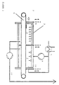
- the laboratory dryer according to FIG. 1 is essentially formed from the two neighboring chambers of the radiation room 1 and the convection room 2.
- the IR radiators 3 are arranged on the ceiling of the radiation room 1. This send their infrared radiation downwards and thus reach a wide area the coating sample 7 transported on the conveyor belt 6. It is According to the invention, however, it is also provided that the infrared radiators can be pivoted in this way to make it vertical (as opposed to the illustration in Figure 1) standing coating sample 7 by vertical irradiation of the surface can dry.
- the radiation chamber 1 is on the input side by the sliding door 8 and on the output side to the convection room 2 through the sliding door 9 closed.
- the convection room 2 there are inlets and outlets for drying gases intended.
- the inlets are on the ceiling of the Convection room 2. Drying gases (preferably air) through a Fan 4 are transported into the convection chamber, pass through the Inlet slots in the ceiling of the convection room 2 in and meet thus perpendicular to the coating sample 7 (lying on the belt).
- Figure 2 is a cross section through the to illustrate the flow Convection room 2 shown. Both through the inlet slots 13 in the ceiling of the room as well as through the side walls is drying gas in the Convection room 2 pressed and thus guided past the sample 7. The Drying gases leave the convection chamber 2 at its lower end and are in a circuit 12 again via the fan 4 to the convection room returned.
- the convection space loses through the degassing line 11 but also a certain proportion of the drying gases. This leakage must Circuit 12 are constantly replaced. This is done by feeding fresher Drying gases via a heater 5.
- the heater 5 can in particular with a temperature control of the system to be connected to the temperature to be able to determine the drying gases precisely.
- the fan can do the same 4 are controlled in terms of their output by the regulation.
- Typical values for the temperature of the drying gases in the convection room 2 are 30 to 100 ° C.
- the speed of the convection flow is typically 0.2 up to 2 m / s in the free cross-section of the furnace, whereby in the air outlet nozzles higher speeds (up to 10 m / s) can occur.
- Typical Dimensions of the laboratory dryer are (length x width x height): 3700 x 1700 x 2200 mm.
Landscapes
- Engineering & Computer Science (AREA)
- Life Sciences & Earth Sciences (AREA)
- Microbiology (AREA)
- Mechanical Engineering (AREA)
- General Engineering & Computer Science (AREA)
- Health & Medical Sciences (AREA)
- Clinical Laboratory Science (AREA)
- Chemical & Material Sciences (AREA)
- Chemical Kinetics & Catalysis (AREA)
- Drying Of Solid Materials (AREA)
- Coating Apparatus (AREA)
Abstract
Description

Claims (10)
- Labortrockner für die Simulation industrieller Lack-Trocknungsanlagen, enthaltenda) einen Bestrahlungsraum (1) mit Infrarotstrahlern (3),b) einen Konvektionsraum (2) mit Mitteln (4,5,13) zur Erzeugung, Lenkung und Bewegung von Trocknungsgasen,c) ein Fördersystem (6) zur Halterung und zum Transport von Beschichtungsproben (7) durch den Bestrahlungsraum (1) und den Konvektionsraum (2),d) Türsysteme (8,9,10) am Eingang und Ausgang des Labortrockners sowie zwischen den Belüftungsraum (1) und dem Konvektionsraum (2).
- Labortrockner nach Anspruch 1,
dadurch gekennzeichnet, daß eine Heizung (5) für die Trocknungsgase vorhanden ist. - Labortrockner nach einem der Ansprüche 1 oder 2,
dadurch gekennzeichnet, daß die Heizleistung der IR-Strahler (3) zeitlich gesteuert, insbesondere konstant vorgewählt, oder über Meßfühler rückgekoppelt geregelt werden kann. - Labortrockner nach einem der Ansprüche 1 bis 3,
dadurch gekennzeichnet, daß Temperatur und/oder Volumenstrom der Trocknungsgase zeitlich gesteuert oder über Meßfühler rückgekoppelt geregelt werden können. - Labortrockner nach einem der Ansprüche 1 bis 4,
dadurch gekennzeichnet, daß das Fördersystem (6) mit einer Steuerung oder Regelung für den Ablauf des Transportes verbunden ist. - Labortrockner nach einem der Ansprüche 1 bis 5,
dadurch gekennzeichnet, daß das Fördersystem (6) ein Laufband oder Kettenförderer ist. - Labortrockner nach einem der Ansprüche 1 bis 6,
dadurch gekennzeichnet, daß Strahlungsraum (1) und Konvektionsraum (2) an ein Entlüftungssystem (11) angeschlossen sind. - Labortrockner nach einem der Ansprüche 1 bis 7,
dadurch gekennzeichnet, daß die Trocknungsgase teilweise in einem Kreislauf (12) geführt werden. - Labortrockner nach einem der Ansprüche 1 bis 8,
dadurch gekennzeichnet, daß die Strahlungsrichtung der Infrarotstrahler und/oder die Strömungsrichtung der Trocknungsgase derart verändert werden kann, daß die bevorzugt getrocknete Fläche der Beschichtungsproben um 90 ° gedreht ist. - Verfahren zur Simulation industrieller Lacktrocknungsanlagen, umfassenda) die Herstellung von Beschichtungsproben (7),b) den Transport zu und ggfs. stationären Aufenthalt von Beschichtungsproben (7) in einem Bestrahlungsraum (1),c) die Einwirkung von IR-Strahlung auf die Beschichtungsproben (7), vorzugsweise nach einem geregelten Temperaturverlauf,d) den Weitertransport zu und ggfs. stationären Aufenthalt der Beschichtungsproben (7) in einem dem Bestrahlungsraum (1) benachbarten Konvektionsraum (2), unde) das Umspülen der Beschichtungsproben (7) mit Trocknungsgasen, vorzugsweise Luft, bei denen vorzugsweise Temperatur und Volumenstrom geregelt sind.
Applications Claiming Priority (3)
| Application Number | Priority Date | Filing Date | Title |
|---|---|---|---|
| DE19628831A DE19628831A1 (de) | 1996-07-17 | 1996-07-17 | Labortrockner |
| DE19628831 | 1996-07-17 | ||
| US08/896,247 US5888592A (en) | 1996-07-17 | 1997-07-17 | Laboratory drier and method |
Publications (2)
| Publication Number | Publication Date |
|---|---|
| EP0825403A2 true EP0825403A2 (de) | 1998-02-25 |
| EP0825403A3 EP0825403A3 (de) | 1998-03-11 |
Family
ID=26027609
Family Applications (1)
| Application Number | Title | Priority Date | Filing Date |
|---|---|---|---|
| EP97112127A Withdrawn EP0825403A3 (de) | 1996-07-17 | 1997-07-16 | Labortrockner |
Country Status (3)
| Country | Link |
|---|---|
| US (1) | US5888592A (de) |
| EP (1) | EP0825403A3 (de) |
| DE (1) | DE19628831A1 (de) |
Cited By (2)
| Publication number | Priority date | Publication date | Assignee | Title |
|---|---|---|---|---|
| CN105674708A (zh) * | 2016-03-18 | 2016-06-15 | 魏中富 | 多重隔断的烘干房及其工作程序 |
| CN111473612A (zh) * | 2020-03-14 | 2020-07-31 | 湖南左逸生态科技有限公司 | 一种静态式烘干设备 |
Families Citing this family (15)
| Publication number | Priority date | Publication date | Assignee | Title |
|---|---|---|---|---|
| US6200650B1 (en) * | 1999-05-26 | 2001-03-13 | Ppg Industries Ohio, Inc. | Processes for drying and curing primer coating compositions |
| US6231932B1 (en) * | 1999-05-26 | 2001-05-15 | Ppg Industries Ohio, Inc. | Processes for drying topcoats and multicomponent composite coatings on metal and polymeric substrates |
| US6863935B2 (en) | 1999-05-26 | 2005-03-08 | Ppg Industries Ohio, Inc. | Multi-stage processes for coating substrates with multi-component composite coating compositions |
| US6291027B1 (en) | 1999-05-26 | 2001-09-18 | Ppg Industries Ohio, Inc. | Processes for drying and curing primer coating compositions |
| US6221441B1 (en) * | 1999-05-26 | 2001-04-24 | Ppg Industries Ohio, Inc. | Multi-stage processes for coating substrates with liquid basecoat and powder topcoat |
| US6113764A (en) * | 1999-05-26 | 2000-09-05 | Ppg Industries Ohio, Inc. | Processes for coating a metal substrate with an electrodeposited coating composition and drying the same |
| US6596347B2 (en) | 1999-05-26 | 2003-07-22 | Ppg Industries Ohio, Inc. | Multi-stage processes for coating substrates with a first powder coating and a second powder coating |
| US7011869B2 (en) * | 1999-05-26 | 2006-03-14 | Ppg Industries Ohio, Inc. | Multi-stage processes for coating substrates with multi-component composite coating compositions |
| WO2002061355A1 (en) * | 2000-12-20 | 2002-08-08 | Yazaki Corporation | Apparatus and related method for rapid cure of sol-gel coatings |
| DE10127962B4 (de) * | 2001-06-08 | 2006-01-26 | Audi Ag | Trocknungsverfahren für auf Bauteile, insbesondere auf Fahrzeugkarosserien oder deren Teile applizierte Lackmaterialien und Vorrichtung zur Durchführung des Trocknungsverfahrens |
| DE10223591A1 (de) * | 2002-05-27 | 2003-12-18 | Albrecht Haensch | Gerät zum Trocknen von frisch-lackierten Finger- und Fußnägeln, ein Nagellacktrockengerät, vorläufig "Beautyboy" genannt |
| DE20304641U1 (de) * | 2003-03-21 | 2003-05-22 | Josef Schiele oHG, 56651 Niederzissen | Beschichtungsvorrichtung |
| DE102015205338A1 (de) * | 2015-03-24 | 2016-09-29 | Cefla Deutschland Gmbh | Trocknungsvorrichtung |
| CA3217713A1 (en) * | 2022-11-15 | 2024-05-15 | Truvian Sciences, Inc. | Systems and methods for drying reagents in multiwell plates |
| USD1116151S1 (en) | 2023-05-03 | 2026-03-03 | Truvian Sciences, Inc. | Monolayer |
Family Cites Families (8)
| Publication number | Priority date | Publication date | Assignee | Title |
|---|---|---|---|---|
| US2391195A (en) * | 1943-03-16 | 1945-12-18 | J O Ross Engineering Corp | Drier |
| GB1582437A (en) * | 1977-09-26 | 1981-01-07 | Casburt Ltd | Apparatus for drying ceramic articles |
| GB2047396B (en) * | 1979-03-29 | 1983-08-03 | Casburt Ltd | Drying slurries |
| DE3402505A1 (de) * | 1983-01-25 | 1984-08-09 | Citizen Watch Co. Ltd., Tanashi, Tokyo | Vorrichtung und verfahren zum aushaerten von unter lichteinwirkung aushaertenden kunstharzklebern |
| DE3406789C1 (de) * | 1984-02-24 | 1989-07-20 | Adolf 7251 Weissach Berkmann | Verfahren zum Trocknen von insbesondere pulverbeschichteten Werkstuecken durch Infrarotstrahlung |
| SE453222B (sv) * | 1985-08-15 | 1988-01-18 | Tri Innovations Ab | Vermebehandlingsugn |
| DE3809654C1 (en) * | 1988-03-22 | 1989-11-09 | Adolf 7251 Weissach De Berkmann | Device for drying coated, in particular powder-coated workpieces by IR radiation |
| DE3821848C1 (de) * | 1988-06-29 | 1989-02-16 | Herberts Gmbh, 5600 Wuppertal, De |
-
1996
- 1996-07-17 DE DE19628831A patent/DE19628831A1/de not_active Withdrawn
-
1997
- 1997-07-16 EP EP97112127A patent/EP0825403A3/de not_active Withdrawn
- 1997-07-17 US US08/896,247 patent/US5888592A/en not_active Expired - Lifetime
Non-Patent Citations (1)
| Title |
|---|
| None |
Cited By (2)
| Publication number | Priority date | Publication date | Assignee | Title |
|---|---|---|---|---|
| CN105674708A (zh) * | 2016-03-18 | 2016-06-15 | 魏中富 | 多重隔断的烘干房及其工作程序 |
| CN111473612A (zh) * | 2020-03-14 | 2020-07-31 | 湖南左逸生态科技有限公司 | 一种静态式烘干设备 |
Also Published As
| Publication number | Publication date |
|---|---|
| DE19628831A1 (de) | 1998-01-22 |
| US5888592A (en) | 1999-03-30 |
| EP0825403A3 (de) | 1998-03-11 |
Similar Documents
| Publication | Publication Date | Title |
|---|---|---|
| DE19628831A1 (de) | Labortrockner | |
| EP1080333B1 (de) | Vorrichtung und verfahren zum vakuumtrocknen | |
| DE69115831T2 (de) | Verbesserungen für Pulverbeschichtungskabinen mit geregelter Lüftung zur Beschichtung von Kraftfahrzeugen | |
| DE102010024840B4 (de) | Trockner | |
| DE19937901A1 (de) | Trockner für eine Lackieranlage | |
| EP1208341A1 (de) | Lacktrockner und lacktrockneranlage | |
| WO2012167885A1 (de) | Lackieranlage | |
| DE69002298T2 (de) | Vakuumtrocknungsverfahren für Stückgüter und Vorrichtung zur Durchführung des Verfahrens. | |
| EP0348882B1 (de) | Verfahren und Vorrichtung zum Herstellen eines Probestücks für die Qualitätsprüfung wasserlöslicher Lacke | |
| WO2005014182A2 (de) | Vorrichtung zur aushärtung einer aus einem material, das unter elektromagnetischer strahlung aushärtet, insbesondere aus einem uv-lack oder thermisch aushärtendem lack bestehenden beschichtung eines gegenstandes | |
| DD229613A5 (de) | Vorrichtung zum auftragen von beschichtungsmedien | |
| DE102010002179A1 (de) | Schleuse zum Überführen eines Werkstücks zwischen einem Außenraum und einem Innenraum eines Werkstückbehandlungsbereichs | |
| DE8434317U1 (de) | Bestrahlungseinheit in form eines portals, insbesondere als trocken- und einbrennkanal fuer die automobilindustrie | |
| DE102010012173B3 (de) | Vorrichtung zum Trocknen von Gegenständen | |
| EP2466237B1 (de) | Infrarot-Trocknungsanlage | |
| DE102015001408A1 (de) | Anlage zum Formhärten von Werkstücken | |
| DE69603391T2 (de) | Trockner für Tonwaren | |
| WO2025036528A1 (de) | Temperieranlage zum temperieren von werkstücken und verfahren zum temperieren von werkstücken | |
| DE60023444T2 (de) | Vorrichtung zur hochtemperaturwärmebehandlung von holzartigem material | |
| DE3016437C2 (de) | ||
| DE102010012534B4 (de) | Anlage zum Beschichten von Gegenständen und Aushärten der Beschichtung mit elektromagnetischer Strahlung | |
| WO2002000377A1 (de) | Verfahren zum sintern von aluminium-basierten sinterteilen sowie vorrichtung zum sintern von aluminium-basierten sinterteilen | |
| DE3902679A1 (de) | Verfahren und vorrichtung zur kontinuierlichen behandlung von pflanzlichen produkten, wie bohnen, insbesondere kakaobohnen, kernen, getreide u. dgl. | |
| DE2852815C2 (de) | ||
| DE3914220C2 (de) |
Legal Events
| Date | Code | Title | Description |
|---|---|---|---|
| PUAI | Public reference made under article 153(3) epc to a published international application that has entered the european phase |
Free format text: ORIGINAL CODE: 0009012 |
|
| PUAL | Search report despatched |
Free format text: ORIGINAL CODE: 0009013 |
|
| AK | Designated contracting states |
Kind code of ref document: A2 Designated state(s): DE ES FR GB IT NL SE |
|
| AX | Request for extension of the european patent |
Free format text: AL;LT;LV;RO;SI |
|
| AK | Designated contracting states |
Kind code of ref document: A3 Designated state(s): AT BE CH DE DK ES FI FR GB GR IE IT LI LU MC NL PT SE |
|
| AX | Request for extension of the european patent |
Free format text: AL;LT;LV;RO;SI |
|
| 17P | Request for examination filed |
Effective date: 19980821 |
|
| AKX | Designation fees paid |
Free format text: DE ES FR GB IT NL SE |
|
| RBV | Designated contracting states (corrected) |
Designated state(s): DE ES FR GB IT NL SE |
|
| 17Q | First examination report despatched |
Effective date: 20000614 |
|
| STAA | Information on the status of an ep patent application or granted ep patent |
Free format text: STATUS: THE APPLICATION IS DEEMED TO BE WITHDRAWN |
|
| 18D | Application deemed to be withdrawn |
Effective date: 20001029 |