EP0825464B1 - Procédé de fabrication et d'assemblage d'un dispositif de couplage optique collectif sur l'extrémité d'un faisceau de plusieurs fibres optiques monomodes - Google Patents
Procédé de fabrication et d'assemblage d'un dispositif de couplage optique collectif sur l'extrémité d'un faisceau de plusieurs fibres optiques monomodes Download PDFInfo
- Publication number
- EP0825464B1 EP0825464B1 EP97401942A EP97401942A EP0825464B1 EP 0825464 B1 EP0825464 B1 EP 0825464B1 EP 97401942 A EP97401942 A EP 97401942A EP 97401942 A EP97401942 A EP 97401942A EP 0825464 B1 EP0825464 B1 EP 0825464B1
- Authority
- EP
- European Patent Office
- Prior art keywords
- fibres
- fiber
- index
- lengths
- optical
- Prior art date
- Legal status (The legal status is an assumption and is not a legal conclusion. Google has not performed a legal analysis and makes no representation as to the accuracy of the status listed.)
- Expired - Lifetime
Links
- 230000003287 optical effect Effects 0.000 title claims description 43
- 230000008878 coupling Effects 0.000 title claims description 39
- 238000010168 coupling process Methods 0.000 title claims description 39
- 238000005859 coupling reaction Methods 0.000 title claims description 39
- 238000000034 method Methods 0.000 title claims description 28
- 239000013307 optical fiber Substances 0.000 title claims description 14
- 238000004519 manufacturing process Methods 0.000 title claims description 9
- VYPSYNLAJGMNEJ-UHFFFAOYSA-N Silicium dioxide Chemical compound O=[Si]=O VYPSYNLAJGMNEJ-UHFFFAOYSA-N 0.000 claims description 80
- 239000000377 silicon dioxide Substances 0.000 claims description 40
- 230000005693 optoelectronics Effects 0.000 claims description 8
- 239000000835 fiber Substances 0.000 description 128
- YFXPPSKYMBTNAV-UHFFFAOYSA-N bensultap Chemical compound C=1C=CC=CC=1S(=O)(=O)SCC(N(C)C)CSS(=O)(=O)C1=CC=CC=C1 YFXPPSKYMBTNAV-UHFFFAOYSA-N 0.000 description 13
- 238000006073 displacement reaction Methods 0.000 description 5
- 238000003776 cleavage reaction Methods 0.000 description 3
- 230000000977 initiatory effect Effects 0.000 description 3
- 230000007017 scission Effects 0.000 description 3
- 238000005476 soldering Methods 0.000 description 3
- 238000003466 welding Methods 0.000 description 3
- 238000010438 heat treatment Methods 0.000 description 2
- 238000005286 illumination Methods 0.000 description 2
- 238000009434 installation Methods 0.000 description 2
- 238000005259 measurement Methods 0.000 description 2
- 239000004065 semiconductor Substances 0.000 description 2
- 238000013519 translation Methods 0.000 description 2
- XUIMIQQOPSSXEZ-UHFFFAOYSA-N Silicon Chemical compound [Si] XUIMIQQOPSSXEZ-UHFFFAOYSA-N 0.000 description 1
- 230000006978 adaptation Effects 0.000 description 1
- 238000003491 array Methods 0.000 description 1
- 210000001520 comb Anatomy 0.000 description 1
- 238000004891 communication Methods 0.000 description 1
- 238000005520 cutting process Methods 0.000 description 1
- 230000007423 decrease Effects 0.000 description 1
- 238000010586 diagram Methods 0.000 description 1
- 238000009826 distribution Methods 0.000 description 1
- 230000000694 effects Effects 0.000 description 1
- 238000005516 engineering process Methods 0.000 description 1
- 239000003999 initiator Substances 0.000 description 1
- 238000005459 micromachining Methods 0.000 description 1
- 230000000737 periodic effect Effects 0.000 description 1
- 238000012545 processing Methods 0.000 description 1
- 230000000644 propagated effect Effects 0.000 description 1
- 230000001902 propagating effect Effects 0.000 description 1
- 229910052710 silicon Inorganic materials 0.000 description 1
- 239000010703 silicon Substances 0.000 description 1
Images


Classifications
-
- G—PHYSICS
- G02—OPTICS
- G02B—OPTICAL ELEMENTS, SYSTEMS OR APPARATUS
- G02B6/00—Light guides; Structural details of arrangements comprising light guides and other optical elements, e.g. couplings
- G02B6/24—Coupling light guides
- G02B6/255—Splicing of light guides, e.g. by fusion or bonding
- G02B6/2552—Splicing of light guides, e.g. by fusion or bonding reshaping or reforming of light guides for coupling using thermal heating, e.g. tapering, forming of a lens on light guide ends
-
- G—PHYSICS
- G02—OPTICS
- G02B—OPTICAL ELEMENTS, SYSTEMS OR APPARATUS
- G02B6/00—Light guides; Structural details of arrangements comprising light guides and other optical elements, e.g. couplings
- G02B6/24—Coupling light guides
- G02B6/26—Optical coupling means
- G02B6/32—Optical coupling means having lens focusing means positioned between opposed fibre ends
-
- G—PHYSICS
- G02—OPTICS
- G02B—OPTICAL ELEMENTS, SYSTEMS OR APPARATUS
- G02B6/00—Light guides; Structural details of arrangements comprising light guides and other optical elements, e.g. couplings
- G02B6/24—Coupling light guides
- G02B6/42—Coupling light guides with opto-electronic elements
- G02B6/4201—Packages, e.g. shape, construction, internal or external details
- G02B6/4202—Packages, e.g. shape, construction, internal or external details for coupling an active element with fibres without intermediate optical elements, e.g. fibres with plane ends, fibres with shaped ends, bundles
- G02B6/4203—Optical features
-
- G—PHYSICS
- G02—OPTICS
- G02B—OPTICAL ELEMENTS, SYSTEMS OR APPARATUS
- G02B6/00—Light guides; Structural details of arrangements comprising light guides and other optical elements, e.g. couplings
- G02B6/24—Coupling light guides
- G02B6/42—Coupling light guides with opto-electronic elements
- G02B6/4201—Packages, e.g. shape, construction, internal or external details
- G02B6/4249—Packages, e.g. shape, construction, internal or external details comprising arrays of active devices and fibres
Definitions
- the present invention relates to a method of manufacturing and assembling a collective optical coupling device on the end of a bundle of several single-mode fibers, in order to allow the optical coupling of said single mode fibers with an optoelectronic module.
- the field of the invention is that of optical telecommunications and more particularly that of distribution networks which concern short distance links and require effort important in terms of cost both in terms of infrastructure as end components.
- the wavelength is most often 1.3 or 1.55 ⁇ m.
- optical coupling constitutes a step of which it is necessary to lower the cost.
- One solution is to treat this step collectively.
- the difficulty is twofold: on the one hand it is linked to the mismatch in the shape and size of the modes optics of the elements to be coupled, on the other positioning details which are submicron.
- the coupled power drops by 1 dB when moving away from a distance less than micrometer of the optimal position in the plane perpendicular to the optical axis, and a few micrometers ( ⁇ m) on the optical axis.
- the passive assembly between bars of fiber components and combs, which consists of position the different elements without feeding the components, is difficult to achieve.
- K. SHIRAISHI et al. offer in particular a lens consisting of a fiber section without end core hemispherical, obtained by micro-machining, welded to a single mode fiber with locally enlarged core by heating.
- the coupling rates obtained were with severe positioning tolerances.
- Document WO-A-86 04156 describes an optical coupling device between a single mode fiber and an optoelectronic module.
- the coupling device comprises a lens formed of a cylindrical section of index gradient fiber having a diameter 125 ⁇ m exterior tuned to single-mode fiber.
- the Patent Abstracts of Japan document summarizing the Japanese patent application for publication number JP-58202413 describes an optical coupling device between a single mode fiber and a laser.
- the coupling device present comprises a lens and a section of silica fiber placed between the single-mode fiber and the lens.
- the fiber stretch silica thus arranged improves the coupling between the laser and the single mode optical fiber.
- the coupling device comprises a fiber bar silica. This device is soldered to one end of the optical fiber and cut to a length defined. The free end is rounded off by heat treatment. The length of the coupling device is greater than the diameter of the single mode fiber.
- Document EP-A-0 531 225 describes a method of cleaving an optical fiber intended to obtain an oblique face at the end of an optical fiber. Two points of the fiber optics are moved transversely relative to each other and a fracture initiator is made in the fiber between the displaced points. This process is particularly applied to an optical fiber with a diameter of 125 ⁇ m. The process described is also applicable to the cleavage of a plurality of optical fibers.
- the first object of the present invention is to propose a method for manufacturing a coupling allowing the tolerances to be relaxed fiber positioning on the optical axis and in the perpendicular plane of this axis.
- the sections of silica are replaced by any type of fiber of suitable index, a fiber with index jump for example.
- an optical coupling device will also be described between minus a single-mode fiber and an optoelectronic module, comprising at least one lens, in which each lens is formed by a cylindrical section fiber with an index gradient of 125 ⁇ m in diameter exterior, not covered by the present invention.
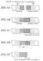
- a process includes the assembly steps, to a ribbon of single-mode fibers 10, a multimode fiber ribbon with a gradient of index 20 and fracture of index gradient fibers.
- An embodiment of the method according to the invention includes (Fig. 2A-2J) the steps for assembling a fiber ribbon multimode gradient index 20 to a ribbon of fibers silica 30, fracture of silica fibers 30, assembly of this set to a ribbon of monomode fibers 10 and finally fiber fracture of the multimode fiber ribbon to index gradient 20 extended by sections of silica fiber.
- the beams propagate periodically following the optical axis. This is due to lateral refractions successive periods undergone by the electromagnetic wave when propagated in an index medium which decreases from the center of the fiber to the periphery.
- the period P (often called pitch) depends on the profile fiber index, which follows a parabolic law, and the wavelength of the light propagating there.
- the mode adaptation between the object and the image is made thanks to the fiber section with gradient index of the same way as with a gradient lens of standard plane-plane index (10).
- silica The role of silica is to spatially extend the light beam at the output of single mode fiber. This extension allows to use all the volume of the gradient index. The index gradient segment is then best used as a lens since the occupancy volume of the light beam is equal to volume of the index gradient.
- silica sections could be replaced by sections of fibers of suitable index, fibers with hint hints for example
- Figure 3 qualitatively illustrates the beam propagation difference with and without section of silica between the single mode fiber and the gradient index lens. (NB: the actual odds do not are not respected)
- the silica sections can have a zero length, in which case the index gradient fiber ribbon is directly soldered to the ribbon of single-mode fibers.
- the maximum mode diameter is of the order of 28 ⁇ m for a length of index gradient of P / 4 (ie 365 ⁇ m), the working distance is then zero.
- the maximum distance between fibers is 460 ⁇ m, for an associated mode diameter of 20 ⁇ m.
- the maximum mode diameter is 80 ⁇ m instead of 28 and the maximum distance between fibers is 1.8 mm instead of 460 ⁇ m.
- the loss of coupling being equivalent in both cases (0.5 db).
- optical coupling devices produced according to the method of the invention have several applications in transmitter or receiver modules multichannel in the field of telecommunications by optical fiber.
- This optical system is compatible in particular with a passive collective assembly on PIN photodiode array silicon platform or semiconductor lasers in front of ribbons single mode fibers.
- connectors high-performance and highly aligned multi-path connectors tolerant.
- the multimode gradient fiber section index only soldered at the end of single-mode fiber does not allow not to adapt the diameter of the mode at the optical output to that of the laser (approximately 2 ⁇ m). Indeed, this diameter does not cannot go below 10 ⁇ m, and this for a length of P / 2 index gradient, i.e. 730 ⁇ m.
- the silica section typically of 500 ⁇ m between the index gradient lens (typically 400 ⁇ m in length) and the single-mode fiber, a mode diameter is obtained at the optical output adapted to that of the laser.
- This improves the coupling performance, the losses typically go from 10 to 4.5 db for lasers with 1.6 ⁇ m mode diameter. It is a very good performance for optics produced by a simple entirely collective process.
- the laser-fiber working distance is of the order of 50 ⁇ m, instead of contact for the cleaved fiber or the section with a pure index gradient.
- Figure 4 shows the block diagram of coupling between a laser strip and a ribbon of single mode fibers provided with a device according to the invention.
- angles of divergence as well as the mode rays of the Gaussian beam of the laser measured at 1 / e 2 of the maximum intensity in the planes parallel and perpendicular to the plane of the junction of the laser are the following:
- the coupling losses between the laser described above and the optical device presented in table T2 are 3.9 dB, for a working distance of 63 ⁇ m (T2) I (microns) L (microns) working distance ( ⁇ m) coupling losses (dB) tolerances in x and y at -1dB ( ⁇ m) tolerance in z at -1 dB ( ⁇ m) 1063 330 63 3.9 ⁇ 1.1 ⁇ 6
- the coupling efficiency between the same laser and a cleaved single-mode fiber is 9.1 dB for a working distance of 20 ⁇ m, it is 12 dB for a working distance of 63 ⁇ m.
- the Gaussian beam of the cleaved single-mode fiber used has a symmetry of revolution and a fashion radius 4.5 ⁇ m, or a half angle of divergence of 5.2 °.
- the cleaved fiber should be in contact with the laser to get the least loss, 8.6 dB, but you can't place it there without damaging the laser.
- the illustrated device therefore makes it possible to reduce coupling losses compared to a fiber cleaved placed at best and increase the distance of 63 ⁇ m work.
- the optical coupling device makes it possible to obtain the illumination of PIN photodiodes.
- the optical device described in table T3 allows you to move the focus point back from 0 to 200 ⁇ m and increase the mode diameter from 9 to 12 ⁇ m, compared to a cleaved fiber.
- optical coupling device has been represented schematically on the Figure 5 in a fiber connector application fiber, and is not covered by the claims.
- positioning tolerances at -1 dB in the plane perpendicular to the optical axis between two fibers of the device are ⁇ 5 ⁇ m against ⁇ 1.5 ⁇ m between two cleaved fibers.
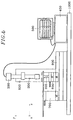
- optical devices are produced according to the process using a standard tape welder and the fractures of the sections of precise length are carried out well on the bench shown in Figure 6.
- the video microscope 300 is connected to a camera 300 whose image is displayed on a video monitor 500 after processing by a 400 distance measurement system. system projects lines that we can move on the screen and allows, with prior calibration, measure distances.
- the fracturing pliers 10 can move according to three directions x, y and z using block 600 including 3 manual displacement stages micrometric, itself fixed to the rail 900 by through a jumper.
- Alignment between the welding plane and the trace of the knife is done visually using the video microscope.
- the displacement of the ribbon is adjusted to the desired dimension thanks to the 400 measurement system.
- the video microscope is maintained by a gallows 800, the whole and supported by a stable base 1000.
Landscapes
- Physics & Mathematics (AREA)
- General Physics & Mathematics (AREA)
- Optics & Photonics (AREA)
- Engineering & Computer Science (AREA)
- Plasma & Fusion (AREA)
- Optical Couplings Of Light Guides (AREA)
Description
- Dans une application de mise en oeuvre du procédé le module optoélectronique est constitué de composants actifs dont le nombre correspond au nombre de fibres à coupler.
- Ces composants actifs sont soit des lasers soit des photodiodes.
- Dans le cas où le dispositif réalise un couplage entre plusieurs fibres monomodes et un module optoélectronique, les fibres monomodes sont dans une structure sous forme de ruban ;
- Selon certaines applications, le module
électronique est composé d'un ensemble de composants
actifs ;
- les composants actifs sont des lasers ;
- les composants actifs sont des photodiodes ;
- Pour d'autres applications, le module électronique est composé soit d'une fibre monomode soit d'un faisceau de fibres, le dispositif servant alors à coupler des fibres optiques entre-elles ;
- Selon un mode préféré de réalisation, les fibres sont structurées sous forme d'au moins un ruban.
- Mise en place et alignement des deux rubans de fibres 10 et 20 dans la soudeuse, (1A)
- Soudure des fibres des deux rubans 10, 20, (1B)
- Alignement du plan de soudure avec la trace du plan de fracture, 1C
- Déplacement de l'ensemble d'une distance L et amorce de fracture, 1D
- Fracture du ruban de fibres multimodes à gradient d'indice, 1E.
- dénudage et clivage des rubans de silice 30 et de fibres multimodes à gradient d'indice 20 et mise en place dans une soudeuse à structure périodique en V selon un pas correspondant au pas du ruban utilisé, 250 µm par exemple, chaque V correspondant au diamètre extérieur d'une fibre soit 125 µm par exemple. (figure 2A)
- soudage du ruban de fibres de silice 30 au ruban de fibres à gradient d'indice 20 (2B),
- Alignement du plan de soudure avec la trace du plan de fracture (2C),
- Translation de l'ensemble sur une distance 1 puis amorce de la fracture (2D).
- Fracture des fibres du ruban de fibres de silice à l'aide d'un banc de fracture de manière à réaliser n tronçons de silice de longueur l, n étant le nombre de fibres comprises dans le ruban.
- Reproduction de ces étapes sur l'ensemble ainsi réalisé et un ruban de fibres monomodes 10. On obtient ainsi un dispositif de couplage optique collectif constitué de tronçons cylindriques de fibres à continuité de forme de bout en bout :
- Mise en place et alignement des rubans 10 et 20 dans la soudeuse, (2G)
- Soudure des fibres monomodes aux tronçons de silice 31, (2G)
- Alignement du plan de soudure avec le plan de fracture, (2H)
- Déplacement de l'ensemble d'une distance L et amorce de fracture, (2I)
- Fracture du ruban de fibres multimodes à gradient d'indice. (2J)
- la zone 1, dans laquelle l'extension spatiale du faisceau lumineux est supérieure à celle obtenue sans tronçon de silice.
- la zone 2, dans laquelle l'extension spatiale du faisceau lumineux est inférieure à celle obtenue sans tronçon de silice.
Avec un tronçon de silice interposé entre la lentille à gradient d'indice et la fibre monomode le diamètre de mode maximum est de 80 µm au lieu de 28 et la distance maximum entre fibres est de 1.8 mm au lieu de 460 µm. La perte de couplage étant équivalente dans les deux cas (0.5 db).
De plus, du fait ,de la présence du tronçon de silice, la distance de travail laser-fibre est de l'ordre de 50 µm, au lieu du contact pour la fibre clivée ou le tronçon de gradient d'indice pur.

| (T2) | |||||
| I(µm) | L(µm) | distance de travail (µm) | pertes de couplage (dB) | tolérances en x et y à -1dB (µm) | tolérance en z à -1 dB (µm) |
| 1063 | 330 | 63 | 3.9 | ±1.1 | ±6 |
| (T3) | |||
| 1(µm) | L(µm) | distance de focalisation z (µm) | diamètre de mode D en z (µm) |
| 169 | 350 | 200 | 12 |
Claims (6)
- Procédé de fabrication et d'assemblage d'un dispositif optique de couplage optique sur l'extrémité d'un faisceau (10) de plusieurs fibres monomodes, en vue de permettre le couplage optique desdites fibres monomodes avec un module optoélectronique (40), caractérisé en ce que ledit procédé comporte au moins les étapes suivantes:assemblage collectif des faces terminales des fibres d'un faisceau (20) de plusieurs fibres à gradient d'indice aux faces terminales des fibres respectives d'un faisceau (30) de plusieurs fibres de silice,fracture collective des fibres du faisceau (30) de fibres de silice de manière à laisser des tronçons de fibres de silice (31) accolés aux fibres respectives du faisceau (20) de fibres à gradient d'indice,assemblage collectif des faces terminales des tronçons de fibres de silice (31) ainsi accolés aux fibres respectives du faisceau (20) aux faces terminales des fibres respectives d'un faisceau (10) de plusieurs fibres monomodes, etfracture collective des fibres du faisceau (20) de fibres à gradient d'indice ainsi reliées aux fibres respectives du faisceau (10) de fibres monomodes via les tronçons de fibres de silice (31) de manière à laisser accolés à ces tronçons (31) des tronçons de fibres à gradient d'indice destinés chacun à former une lentille sur l'extrémité correspondante desdits tronçons de fibres de silice (31), ces tronçons de fibres de silice (31) ayant en outre été réalisés pour placer les faces terminales des fibres monomodes à la bonne distance desdits tronçons de fibres à gradient d'indice destinés à servir de lentilles accolés aux extrémités des tronçons de fibres de silice (31) respectifs et/ou à adapter l'indice du milieu de propagation desdites fibres monomodes auxdites lentilles.
- Procédé selon la revendication 1, caractérisé en ce que le faisceau (30) de fibres de silice est remplacé par un faisceau de fibres à saut d'indice.
- Procédé selon l'une quelconque des revendications précédentes, caractérisé en ce que les faisceaux de fibres (10, 20, 30) ont une structure sous forme d'au moins un ruban.
- Procédé selon l'une des revendications précédentes, caractérisé en ce que les fibres monomodes ainsi pourvues desdits tronçons de fibre de silice (31) prolongés par lesdits tronçons de fibres à gradient d'indice sont destinées à être couplées avec un module optoélectronique constitué d'un ensemble d'au moins un composant actif.
- Procédé selon la revendication 4, caractérisé en ce que le composant actif est un laser.
- Procédé selon la revendication 4, caractérisé en ce que le composant actif est une photodiode.
Applications Claiming Priority (2)
| Application Number | Priority Date | Filing Date | Title |
|---|---|---|---|
| FR9610327 | 1996-08-21 | ||
| FR9610327A FR2752623B1 (fr) | 1996-08-21 | 1996-08-21 | Procede de fabrication d'un dispositif de couplage optique collectif et dispositif obtenu par un tel procede |
Publications (2)
| Publication Number | Publication Date |
|---|---|
| EP0825464A1 EP0825464A1 (fr) | 1998-02-25 |
| EP0825464B1 true EP0825464B1 (fr) | 2004-01-21 |
Family
ID=9495139
Family Applications (1)
| Application Number | Title | Priority Date | Filing Date |
|---|---|---|---|
| EP97401942A Expired - Lifetime EP0825464B1 (fr) | 1996-08-21 | 1997-08-18 | Procédé de fabrication et d'assemblage d'un dispositif de couplage optique collectif sur l'extrémité d'un faisceau de plusieurs fibres optiques monomodes |
Country Status (4)
| Country | Link |
|---|---|
| US (1) | US6014483A (fr) |
| EP (1) | EP0825464B1 (fr) |
| DE (1) | DE69727270T2 (fr) |
| FR (1) | FR2752623B1 (fr) |
Families Citing this family (41)
| Publication number | Priority date | Publication date | Assignee | Title |
|---|---|---|---|---|
| US6111645A (en) | 1991-04-29 | 2000-08-29 | Massachusetts Institute Of Technology | Grating based phase control optical delay line |
| US6485413B1 (en) | 1991-04-29 | 2002-11-26 | The General Hospital Corporation | Methods and apparatus for forward-directed optical scanning instruments |
| US6058228A (en) * | 1997-10-06 | 2000-05-02 | Nec Research Institute, Inc. | Cost-effective side-coupling polymer fiber optics for optical interconnections |
| JPH11305082A (ja) * | 1998-02-23 | 1999-11-05 | Oki Electric Ind Co Ltd | 光結合モジュール |
| FR2794871B1 (fr) * | 1999-06-09 | 2002-07-05 | France Telecom | Procede de realisation collective de micro-lentilles au bout d'un ensemble de fibres optiques du type ruban de fibres |
| US6480650B2 (en) * | 1999-06-30 | 2002-11-12 | Nortel Networks Limited | Fibre termination compound graded index lenses |
| US6445939B1 (en) | 1999-08-09 | 2002-09-03 | Lightlab Imaging, Llc | Ultra-small optical probes, imaging optics, and methods for using same |
| FR2804251B1 (fr) * | 2000-01-26 | 2002-03-08 | France Telecom | Procede et dispositif de commutation en longueur d'onde d'une source laser |
| US6415076B1 (en) * | 2000-02-24 | 2002-07-02 | International Business Machines Corporation | Mode conditioning patch for facilitating signal transmission from single mode optical fiber to multimode optical fiber |
| JP2001326714A (ja) | 2000-05-18 | 2001-11-22 | Nec Corp | 情報処理装置および情報処理方法、並びに記録媒体 |
| US6751369B1 (en) | 2000-07-28 | 2004-06-15 | Moog Components Group Inc. | Fiber lens assembly for singlemode optical switches |
| FR2815421B1 (fr) * | 2000-10-16 | 2003-09-19 | France Telecom | Collimateur optique pour fibres monomodes, fibre monomode a collimateur integre et procede de fabrication |
| JP2002196181A (ja) * | 2000-12-25 | 2002-07-10 | Nippon Sheet Glass Co Ltd | レンズ機能付き光ファイバおよびその製造方法 |
| FR2820827B1 (fr) * | 2001-02-13 | 2004-06-04 | Get Enst Bretagne | Dispositif d'attenuation d'un signal vehicule par fibre optique sous la forme d'un faisceau lumineux, systeme d'attenuation et applications correspondantes |
| US6542665B2 (en) | 2001-02-17 | 2003-04-01 | Lucent Technologies Inc. | GRIN fiber lenses |
| US20020150333A1 (en) * | 2001-02-17 | 2002-10-17 | Reed William Alfred | Fiber devices using grin fiber lenses |
| US6760112B2 (en) | 2001-02-17 | 2004-07-06 | Lucent Technologies Inc. | Grin-fiber lens based optical endoscopes |
| US20020140942A1 (en) * | 2001-02-17 | 2002-10-03 | Fee Michale Sean | Acousto-optic monitoring and imaging in a depth sensitive manner |
| US6873768B2 (en) * | 2001-03-16 | 2005-03-29 | Jds Uniphase Corporation | Compact optical fiber coupler |
| JP2003043270A (ja) * | 2001-08-03 | 2003-02-13 | Japan Aviation Electronics Industry Ltd | 光ファイバ端部構造及びその製造方法 |
| FR2830334B1 (fr) * | 2001-10-01 | 2004-07-16 | Highwave Optical Tech | Composant optique a fonction de separation spectrale |
| US6795242B2 (en) * | 2002-02-06 | 2004-09-21 | Lightwaves 2020, Inc. | Miniature circulator devices and methods for making the same |
| US6813416B2 (en) * | 2002-02-20 | 2004-11-02 | Lightwaves 2020, Inc. | Miniature fiberoptic filter and method of manufacture therefor |
| US20030185269A1 (en) * | 2002-03-26 | 2003-10-02 | Gutin Mikhail A. | Fiber-coupled vertical-cavity surface emitting laser |
| FR2838200B1 (fr) * | 2002-04-08 | 2004-08-06 | Optogone Sa | Collimateur optique pour fibre monomode presentant une section de fibre a gradient d'indice, fibre monomode a coeur etendu et procede de fabrication correspondants |
| FR2839160B1 (fr) * | 2002-04-24 | 2004-10-15 | Optogone Sa | Dispositif optique de filtrage mettant un element diffractif programmable, routeur spatial de bandes spectrales et dispositif de compensation de dispersion chromatique correspondants |
| US6891984B2 (en) * | 2002-07-25 | 2005-05-10 | Lightlab Imaging, Llc | Scanning miniature optical probes with optical distortion correction and rotational control |
| JP4502323B2 (ja) * | 2002-09-25 | 2010-07-14 | ホーヤ コーポレイション ユーエスエイ | 光学装置 |
| CA2461081C (fr) * | 2003-03-27 | 2007-05-22 | Japan Aviation Electronics Industry Limited | Module moniteur optique |
| US7653588B2 (en) * | 2003-04-24 | 2010-01-26 | Chicago Board Options Exchange, Incorporated | Method and system for providing order routing to a virtual crowd in a hybrid trading system |
| US7190864B2 (en) * | 2004-04-02 | 2007-03-13 | Beamtek, Inc. | Fiber collimating lenses and method |
| US7280734B2 (en) * | 2004-09-09 | 2007-10-09 | Micro Optics, Inc. | Expanding single mode fiber mode field for high power applications by fusion with multimode fiber |
| US7920763B1 (en) * | 2007-02-09 | 2011-04-05 | Agiltron, Inc. | Mode field expanded fiber collimator |
| JP2007148450A (ja) * | 2007-03-12 | 2007-06-14 | Kyocera Corp | 光デバイスおよびその製造方法 |
| US7773844B2 (en) * | 2008-05-16 | 2010-08-10 | International Business Machines Corporation | Method for reducing bandwidth loss in data center applications with multiple fiber type connectivity |
| WO2015013264A1 (fr) | 2013-07-22 | 2015-01-29 | Adc Telecommunications, Inc. | Ensemble câble à fibres optiques et connecteur de fibres optiques à fonctionnalité améliorée intégrée |
| US9829647B2 (en) | 2013-07-22 | 2017-11-28 | Commscope Technologies Llc | Expanded beam fiber optic connector, and cable assembly, and methods for manufacturing |
| US10488598B2 (en) | 2015-08-20 | 2019-11-26 | Commscope Technologies Llc | Ferrule assembly with beam expansion section and sacrificial optical fiber |
| US10969560B2 (en) | 2017-05-04 | 2021-04-06 | Lightpath Technologies, Inc. | Integrated optical assembly and manufacturing the same |
| JP7110553B2 (ja) * | 2017-06-26 | 2022-08-02 | 東洋製罐グループホールディングス株式会社 | レンズ付き光ファイバの製造方法、及び切断装置 |
| WO2025216022A1 (fr) * | 2024-04-12 | 2025-10-16 | 日本板硝子株式会社 | Connecteur optique et procédé de fabrication associé |
Citations (3)
| Publication number | Priority date | Publication date | Assignee | Title |
|---|---|---|---|---|
| US4456330A (en) * | 1981-01-17 | 1984-06-26 | International Standard Electric Corporation | Optical coupling system and method for manufacturing same |
| JPH03189607A (ja) * | 1989-12-19 | 1991-08-19 | Nippon Telegr & Teleph Corp <Ntt> | ファイバ形光学結合器の製造法 |
| EP0531225A1 (fr) * | 1991-09-06 | 1993-03-10 | Radiall | Procédé de clivage de fibre optique |
Family Cites Families (11)
| Publication number | Priority date | Publication date | Assignee | Title |
|---|---|---|---|---|
| JPS58202413A (ja) * | 1982-05-21 | 1983-11-25 | Hitachi Ltd | 光フアイバ先端の構造 |
| GB8421105D0 (en) * | 1984-08-20 | 1984-09-26 | British Telecomm | Microlens |
| US4701011A (en) * | 1985-01-15 | 1987-10-20 | American Telephone And Telegraph Company, At&T Bell Laboratories | Multimode fiber-lens optical coupler |
| DE3605659A1 (de) * | 1986-02-21 | 1987-08-27 | Standard Elektrik Lorenz Ag | Ankoppeloptik fuer lichtwellenleiter |
| GB8827242D0 (en) * | 1988-11-22 | 1988-12-29 | Plessey Co Plc | Optical coupling of optical fibres & optical devices |
| US5095519A (en) * | 1990-11-30 | 1992-03-10 | At&T Bell Laboratories | Apparatus and method for producing an in-line optical fiber attenuator |
| CA2098903C (fr) * | 1992-06-24 | 1999-02-16 | Shigeru Hirai | Dispositif fonctionnel a fibre optique |
| FR2699293B1 (fr) * | 1992-12-15 | 1995-03-03 | France Telecom | Système optique monolithique comportant des moyens de couplage perfectionnés entre une fibre optique et un phototransducteur. |
| GB9326429D0 (en) * | 1993-12-24 | 1994-02-23 | Bt & D Technologies Ltd | An optical device and method of making the same |
| US5488506A (en) * | 1994-06-09 | 1996-01-30 | Ceramoptec Industries, Inc. | Enhanced power fiber laser with controllable output beam |
| US5757993A (en) * | 1995-06-05 | 1998-05-26 | Jds Fitel Inc. | Method and optical system for passing light between an optical fiber and grin lens |
-
1996
- 1996-08-21 FR FR9610327A patent/FR2752623B1/fr not_active Expired - Fee Related
-
1997
- 1997-08-13 US US08/910,848 patent/US6014483A/en not_active Expired - Lifetime
- 1997-08-18 DE DE69727270T patent/DE69727270T2/de not_active Expired - Lifetime
- 1997-08-18 EP EP97401942A patent/EP0825464B1/fr not_active Expired - Lifetime
Patent Citations (3)
| Publication number | Priority date | Publication date | Assignee | Title |
|---|---|---|---|---|
| US4456330A (en) * | 1981-01-17 | 1984-06-26 | International Standard Electric Corporation | Optical coupling system and method for manufacturing same |
| JPH03189607A (ja) * | 1989-12-19 | 1991-08-19 | Nippon Telegr & Teleph Corp <Ntt> | ファイバ形光学結合器の製造法 |
| EP0531225A1 (fr) * | 1991-09-06 | 1993-03-10 | Radiall | Procédé de clivage de fibre optique |
Non-Patent Citations (2)
| Title |
|---|
| Journal of Optical Communications, Vol.10, No.2, Juin 1989, pages 61-66 * |
| PATENT ABSTRACTS OF JAPAN vol. 015, no. 449 (P - 1275) 14 November 1994 (1994-11-14) * |
Also Published As
| Publication number | Publication date |
|---|---|
| US6014483A (en) | 2000-01-11 |
| EP0825464A1 (fr) | 1998-02-25 |
| DE69727270D1 (de) | 2004-02-26 |
| DE69727270T2 (de) | 2004-11-25 |
| FR2752623B1 (fr) | 1998-10-30 |
| FR2752623A1 (fr) | 1998-02-27 |
Similar Documents
| Publication | Publication Date | Title |
|---|---|---|
| EP0825464B1 (fr) | Procédé de fabrication et d'assemblage d'un dispositif de couplage optique collectif sur l'extrémité d'un faisceau de plusieurs fibres optiques monomodes | |
| EP0205359B1 (fr) | Composant optoélectronique bidirectionnel formant coupleur optique | |
| FR2699293A1 (fr) | Système optique monolithique comportant des moyens de couplage perfectionnés entre une fibre optique et un phototransducteur. | |
| FR2947347A1 (fr) | Structure et procede d'alignement d'une fibre optique et d'un guide d'ondes submicronique | |
| US20040120672A1 (en) | Waveguides with integrated lenses and reflective surfaces | |
| EP0061378A1 (fr) | Procédé de modification contrôlée des caractéristiques géométriques de l'extrémité d'une fibre optique monomode, et application au couplage optique | |
| EP0677758B1 (fr) | Système optique pour coupler une fibre à mode circulaire et un phototransducteur à mode elliptique et son procédé de fabrication | |
| WO2020254760A1 (fr) | Procédé de fixation d'une fibre optique monomode et d'une fibre optique multimode, équipement de couplage optique | |
| FR2699292A1 (fr) | Procédé de préparation par lentillage multiple d'une fibre optique en vue d'un couplage optimum avec un phototransducteur et système optique obtenu. | |
| FR2838200A1 (fr) | Collimateur optique pour fibre monomode presentant une section de fibre a gradient d'indice, fibre monomode a coeur etendu et procede de fabrication correspondants | |
| EP1183562B1 (fr) | Procede de realisation collective de micro-lentilles au bout d'un ensemble de fibres optiques du type ruban de fibres | |
| FR2860599A1 (fr) | Dispositif de couplage optique d'une fibre monomode multi-coeurs, et procede de fabrication correspondant | |
| Chanclou et al. | Focusing and coupling properties of collective micro-optics on fiber ribbon | |
| EP3987337B1 (fr) | Source lumineuse comportant au moins une puce a semi-conducteur portant au moins une diode | |
| WO2003071326A1 (fr) | Connecteur de ferules optiques | |
| EP1151334B1 (fr) | Dispositif d'attenuation en ligne pour fibre monomode et procede de fabrication associe | |
| CA2424907C (fr) | Dispositif d'injection pour fibre optique et procede de preparation | |
| EP1030412B1 (fr) | Amplificateur optique | |
| FR2822313A1 (fr) | Composant optique a base de fibre bi-coeur avec entrees/sorties en fibres mono-coeur | |
| FR2827969A1 (fr) | Dispositif optique comprenant des fibres a expansion de mode pour la realisation d'au moins une fonction optique, et systeme optique correspondant | |
| FR3139396A1 (fr) | Routeur optique pour la distribution de signaux optiques | |
| Thual et al. | Focusing and coupling properties of collective micro-optics on fiber ribbon | |
| FR2876191A1 (fr) | Procede et dispositif de couplage de composants optiques | |
| FR2747799A1 (fr) | Procede de realisation d'un dispositif de couplage pour fibre optique | |
| Pocha et al. | Glass, Plastic and Semiconductors: Packaging Techniques for Miniature Optoelectric Components |
Legal Events
| Date | Code | Title | Description |
|---|---|---|---|
| PUAI | Public reference made under article 153(3) epc to a published international application that has entered the european phase |
Free format text: ORIGINAL CODE: 0009012 |
|
| AK | Designated contracting states |
Kind code of ref document: A1 Designated state(s): DE FR GB |
|
| 17P | Request for examination filed |
Effective date: 19980624 |
|
| AKX | Designation fees paid |
Free format text: DE FR GB |
|
| RBV | Designated contracting states (corrected) |
Designated state(s): DE FR GB |
|
| 17Q | First examination report despatched |
Effective date: 20020521 |
|
| RTI1 | Title (correction) |
Free format text: PROCESS OF MANUFACTURING AND ASSEMBLING A COLLECTIVE OPTICAL COUPLING DEVICE ONTO THE END OF A BUNDLE OF SEVERAL MONOMODE |
|
| GRAP | Despatch of communication of intention to grant a patent |
Free format text: ORIGINAL CODE: EPIDOSNIGR1 |
|
| GRAS | Grant fee paid |
Free format text: ORIGINAL CODE: EPIDOSNIGR3 |
|
| GRAA | (expected) grant |
Free format text: ORIGINAL CODE: 0009210 |
|
| AK | Designated contracting states |
Kind code of ref document: B1 Designated state(s): DE FR GB |
|
| REG | Reference to a national code |
Ref country code: GB Ref legal event code: FG4D Free format text: NOT ENGLISH |
|
| REF | Corresponds to: |
Ref document number: 69727270 Country of ref document: DE Date of ref document: 20040226 Kind code of ref document: P |
|
| GBT | Gb: translation of ep patent filed (gb section 77(6)(a)/1977) |
Effective date: 20040510 |
|
| PLBE | No opposition filed within time limit |
Free format text: ORIGINAL CODE: 0009261 |
|
| STAA | Information on the status of an ep patent application or granted ep patent |
Free format text: STATUS: NO OPPOSITION FILED WITHIN TIME LIMIT |
|
| 26N | No opposition filed |
Effective date: 20041022 |
|
| REG | Reference to a national code |
Ref country code: FR Ref legal event code: PLFP Year of fee payment: 20 |
|
| PGFP | Annual fee paid to national office [announced via postgrant information from national office to epo] |
Ref country code: GB Payment date: 20160726 Year of fee payment: 20 Ref country code: DE Payment date: 20160721 Year of fee payment: 20 |
|
| PGFP | Annual fee paid to national office [announced via postgrant information from national office to epo] |
Ref country code: FR Payment date: 20160720 Year of fee payment: 20 |
|
| REG | Reference to a national code |
Ref country code: DE Ref legal event code: R071 Ref document number: 69727270 Country of ref document: DE |
|
| REG | Reference to a national code |
Ref country code: GB Ref legal event code: PE20 Expiry date: 20170817 |
|
| PG25 | Lapsed in a contracting state [announced via postgrant information from national office to epo] |
Ref country code: GB Free format text: LAPSE BECAUSE OF EXPIRATION OF PROTECTION Effective date: 20170817 |