EP0825630A2 - Commutateur, en particulier relais - Google Patents
Commutateur, en particulier relais Download PDFInfo
- Publication number
- EP0825630A2 EP0825630A2 EP97112418A EP97112418A EP0825630A2 EP 0825630 A2 EP0825630 A2 EP 0825630A2 EP 97112418 A EP97112418 A EP 97112418A EP 97112418 A EP97112418 A EP 97112418A EP 0825630 A2 EP0825630 A2 EP 0825630A2
- Authority
- EP
- European Patent Office
- Prior art keywords
- contact
- switch according
- switch
- drive part
- voltage
- Prior art date
- Legal status (The legal status is an assumption and is not a legal conclusion. Google has not performed a legal analysis and makes no representation as to the accuracy of the status listed.)
- Granted
Links
Images


Classifications
-
- H—ELECTRICITY
- H01—ELECTRIC ELEMENTS
- H01H—ELECTRIC SWITCHES; RELAYS; SELECTORS; EMERGENCY PROTECTIVE DEVICES
- H01H57/00—Electrostrictive relays; Piezoelectric relays
-
- H—ELECTRICITY
- H01—ELECTRIC ELEMENTS
- H01H—ELECTRIC SWITCHES; RELAYS; SELECTORS; EMERGENCY PROTECTIVE DEVICES
- H01H55/00—Magnetostrictive relays
-
- H—ELECTRICITY
- H01—ELECTRIC ELEMENTS
- H01H—ELECTRIC SWITCHES; RELAYS; SELECTORS; EMERGENCY PROTECTIVE DEVICES
- H01H3/00—Mechanisms for operating contacts
- H01H3/001—Means for preventing or breaking contact-welding
-
- H—ELECTRICITY
- H01—ELECTRIC ELEMENTS
- H01H—ELECTRIC SWITCHES; RELAYS; SELECTORS; EMERGENCY PROTECTIVE DEVICES
- H01H47/00—Circuit arrangements not adapted to a particular application of the relay and designed to obtain desired operating characteristics or to provide energising current
- H01H47/002—Monitoring or fail-safe circuits
Definitions
- the invention relates to a switch, in particular a Relay, according to the preamble of claim 1.
- contact springs are used as switching elements provided by a slide with each other are connected. It is turned into a by the contact springs Starting position, in which the slide on the drive part is present, which is an armature of an electromagnet forms. If the relay is energized, the armature deflected, which opens a break contact of the relay and / or a closer is closed. Once the relay drops, the slider is normally replaced by the Spring preload of the contact spring or an additional Spring pushed back into the starting position. The anchor itself is under its own spring preload, so that it swung back into the starting position when the relay drops out becomes.
- the invention has for its object the generic Train switches so that it consists of only a few Components exists, has only a small construction volume and has a short switching time.
- this is a switching element firmly connected to the drive part, which is a solid-state energy converter is. Because of the fixed connection of switching element and drive part remains with one possible welding of the switching elements to one another also the drive part in its adjusted position, so that simply and without additional sensors this state of the Switch can be detected and evaluated. Because the drive part trained as a solid-state energy converter very short switching times are achieved. Especially the masses to be moved are very small also has an advantageous effect on the switching times. Due to the fixed connection of the switching element and drive part basically two switching elements are sufficient to monitor the proper operation of the switch to be able to.
- Fig. 1 shows a switch 1 in the illustrated embodiment is designed as a relay.
- the desk 1 can also be a quick switch, for example Undervoltage release, a residual current circuit breaker and the like.
- switch 1 described in the form of a relay.
- the switch 1 has two contact springs as switching elements 2, 3, in a known manner in a switch housing 4th are stored.
- the protruding from the switch housing 4 Ends of the contact springs 2, 3 form connections, via which the current is passed on in a known manner.
- the two contact springs 2, 3 can each be a contact piece 5, 6 wear.
- the longer contact spring 2 is firmly connected to an energy converter 7. He is through a ferroelectric piezoceramic, a film that is used for Example made of lead zirconate titanate or polyvinylidene fluoride exists, or through magnetostrictive rare earth metals, such as Terfenol-D.
- the contact spring 2 is bent so elastically that their contact piece 5 in contact with the contact piece 6 the contact spring 3 arrives.
- the schematic representation 1 is the result of the deflection of the Energy converter 7 generated force F and the corresponding Adjustment path s symbolized by an arrow.
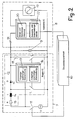
- the desk 1 is to an evaluation electronics 8 and to a control electronics 9 connected.
- the evaluation electronics 8 detects the electrical terminal behavior of the energy converter 7 and gives a corresponding signal to a monitoring unit 10.
- the contact points 5, 6 are not welded together, receives the monitoring unit a corresponding signal. She then enters in turn corresponding signal to the control electronics 9, the can control switch 1 again.
- the Evaluation electronics 8 recognized that a corresponding Delivers blocking signal to the monitoring unit 10. she gives a corresponding signal to the control electronics 9, so that this no longer controls switch 1.
- the energy converter 7 is formed by a piezo element.
- the monitoring unit 10 supplies a control signal to a switch 11 of the control electronics 9. It is identified by a dashed line.
- the switch 11 is followed by a step-up converter 12, which is identified by a dash-dotted line. It transforms a low voltage, for example 24 V, into a high voltage, for example 400 V, required for operating the piezo element 7.
- the step-up converter 12 has, for example, a resistor 13, an inductor 14 and a diode 15. These components are in series with one another and with Switch 11.
- the voltage applied to the piezo element 7 is monitored by an output voltage monitor 16.
- the switch T 1 is parallel to the piezo element 7 (in series with the diode 15) and, like the output voltage monitor 16, is part of the step-up converter 12.
- the switch 11 of the control electronics 9 is opened by the monitoring unit 10 via a corresponding signal, there is no input voltage. This is determined by an input voltage monitor 17 of the step-up converter 12, to which a switch T 2 is connected. It is parallel to the piezo element 7 and in series with a resistor 18 of the step-up converter 12. If there is no input voltage, the switch T 2 is closed by the input voltage monitor 17. As a result, the charge of the piezo element 7 can flow off rapidly via the resistor 18 and the closed switch T 2 . If the piezo element 7 is discharged, the switch T 2 is opened again by the input voltage monitor 17.
- the output voltage monitor 16 and the input voltage monitor 17 are advantageous in an IC chip summarized.
- the evaluation electronics 8 has an oscillator 19 which generates an alternating voltage. It is replaced by a Current / voltage measuring unit 20 is detected, via which Capacitor 21, the piezo element 7 is connected. The Piezo element 7 and capacitor 21 form a load of the oscillator 19.
- the piezo element 7 When the piezo element 7 is excited, it changes Impedance and thus also the voltage or the current. This is detected by the measuring unit 20, the corresponding one Provides signals to an evaluation / decision unit 22. It compares the transmitted values with one predetermined setpoint. It corresponds to a state at which the contact points 5, 6 (Fig. 1) of the switch 1 are not welded together.
- the two measuring units 20 and 22 are advantageous in an IC chip the evaluation electronics 8 summarized.
- the piezo element 7 If the piezo element 7 is excited, then it expands and deflects the contact spring 2 (Fig. 1) until their contact point 5 the contact point 6 of the contact spring 3 touched. If switch 1 is operating correctly returns the contact spring 2 when the piezo element 7 is not is actuated, in its starting position shown in Fig. 1 back, in which the two contact points 5, 6 Distance from each other. If contact points 5, 6 stick to each other due to welding remains also the piezo element 7 deflected, since it is fixed to the Contact spring 2 is connected. This has the consequence that the measuring unit 20 has a current and Measures voltage value.
- the measuring unit 20 then delivers appropriate signals to the evaluation / decision unit 22, which these transmitted signals with a Compare setpoint and if the two measured values deviate a corresponding control signal to the monitoring unit 10 issues. It then provides in connection with the Control electronics 9 that the switch 1 is not again is actuated, as explained with reference to FIG. 1 has been.
- the described relay 1 is corresponding fewer contact springs required.
- the relay has only one single make contact with the two contact springs 2, 3.
- positively driven contacts is in the simplest training in addition to such a closer, there is also an opener required.
- the switch can also be used, for example as a fault current and fault voltage switch, as a circuit breaker or designed as a motor protection switch be.
- the electrical terminal behavior such as transducer resonance or damping, the condition is monitored when there is a load of the energy converter 7 possible. In particular, too an evaluation was carried out in the static operating case will.
- the device described can for this Basically excellent as a relay drive in safety-relevant Facilities are used.
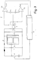
- the energy converter 7 is formed by a piezoelectric bending converter, which can be a two, three or multi-layer converter. In the exemplary embodiment shown, it has two layers which are electrically separated from one another and are firmly connected to one another. If the switch 11 is activated, the one layer of the bending transducer 7 contracts, the second piezo layer also being bent accordingly as a result of the fixed connection. This results in a charge separation in the second piezo layer, ie a voltage pulse occurs which is detected and evaluated by the evaluation electronics 8. It has two comparators 23, 24, to which the bending transducer 7 is connected.
- comparators 23, 24 a reference voltage U ref1 or U ref2 supplied to them is compared with the voltage pulses occurring on the second piezo layer of the bending transducer 7.
- the two comparators 23, 24 deliver a corresponding output signal U out1 and U out2 , which is fed to the monitoring unit 10.
- U out1 and U out2 As has been described in detail with reference to FIGS. 1 and 2, it gives corresponding signals to the control electronics 9, which are of the same design as in the previous exemplary embodiment.
- a two, three or multi-layer converter can also be used in the manner previously described in FIG. 2 and Used and evaluated.
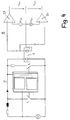
- the exemplary embodiment according to FIG. 4 differs from the previous embodiment only in that a monitoring unit 10, which is connected to the control electronics 9, is not provided.
- the voltage output signals U out1 and U out2 of the comparators 23, 24 of the evaluation electronics 8 are supplied, for example, to a display which lights up when the contact pieces 5, 6 are welded and thus visually indicates an error at the switch 1.
- an acoustic signal can also be generated, for example.
- the embodiment according to FIG. 4 works the same as the embodiment according to FIG. 3.
- Fig. 5 shows in longitudinal section a designed as a relay Switch 1.
- This switch 1 has the piezoelectric Bending transducer 7 with two piezo layers 7a and 7b, which are electrically separated from one another.
- the bending transducer 7 is in a bottom 25 of the switch housing 4 attached.
- the bending transducer 7 is fixed at the upper end connected to a slider 26, which in turn is fixed is connected to the contact spring 2.
- the slider 26 can, for example, on the upper end of the bending transducer 7 put on and held in a clamped manner. Likewise it is possible to unscrew the slider 26 with the bending transducer 7 to connect it, for example on the bending transducer to stick.
- the two form Contact springs 2 and 3 an NC contact, i.e. the contact pieces 5 and 6 of the contact springs 2, 3 lie against each other.
- Relay 1 points to the other, below the drawing level a corresponding closer whose two contact springs carry contact pieces, which are spaced apart when the relay is not energized.
- One of the contact springs of this closer is also firmly with the slide 26 and thus firmly with the bending transducer 7 connected.
- the bending transducer 7 in 5 bent to the right.
- the slider 26 rigidly connected to it accordingly also shifted to the right and takes the Contact spring 2 with.
- the corresponding contact spring of the (not shown) normally open relay 1 taken away.
- the contact piece 5 of the contact spring 2 lifts thereby from the contact piece 6 of the contact spring 3, so that the normally closed contact of the relay is opened.
- Be accordingly on the other side of the relay the contact pieces of the Contact springs of the closer brought into contact with each other.
- FIG. 5 Piezo layer 7b located on the right.
- the in Fig. 5 piezo layer 7a on the left is connected to the evaluation electronics 8 (Fig. 1 to 4) connected, which the Impedance change or occurring voltage pulses Piezo layer 7a evaluates in the manner described. If relay 1 is no longer actuated or the bending transducer 7 no longer controlled, he returns to the in Fig. 5 shown starting position back. About the slider 26 he takes the contact spring 2 with her until you Contact piece 5 on the contact piece 6 of the contact spring 3 for Facility is coming. On the opposite side of the relay become the two contact pieces of the contact springs disengaged from each other again.
- the contact spring 2 of the opener is advantageous in the direction its contact opening (Fig. 5) elastically biased. This supports the bending of the bending transducer 7 in the actuation position, not shown in FIG. 5. In particular when closing the contact 5, 6 of the (not shown) closer the required Contact pressure only insignificant from the force of the Bending converter 7, but mainly from the bias the contact spring 2 determines so that the required Contact pressure is reached properly. The preload the contact spring 2 is selected so that even longer service life of the relay and accordingly Wear of the contact pieces 5, 6 is still sufficient Contact pressure is ensured.
- the contact spring 2 of the (not shown) Closer are biased in the direction of actuation.
- multi-contact relays it is possible to use a Combination of the preloads of the contact springs always to achieve a state of power that prevents the movement of the supports piezoelectric transducer and the required Contact forces generated.
- the piezo layer 7b which is advantageously designed in the form of a strip forms an actuator piezo layer, while the opposite piezo layer 7a is a sensory one Piezo layer forms.
- the bending transducer 7 and the Contact springs 2, 3 can be easily installed in the relay housing 4 mount.
- the slider 26 can also simply on Bending converter 7 and on the corresponding contact springs of the NC and NO contacts of the relay.
- One contact spring 3 each of the break contact and the make contact of relay 1 is not connected to slide 26. It consists of electrically non-conductive material, preferably made of plastic. For easy attachment to reach on the contact springs, the slide 26th with corresponding plug openings for the contact springs Mistake.
- FIGS. 6 and 7 show a further embodiment of a switch designed as a relay 1.
- FIGS. 6 and 7 the two sides of the relay are shown, which have the contact springs 2, 3.
- the contact springs 6 form a closer, while the contact springs 2, 3 form a break contact according to FIG. 7.
- the contact pieces 5, 6 of the contact springs forming the closer 2, 3 (Fig. 6) have in the starting position Distance from each other.
- the contact pieces 5, 6 of the opener Forming contact springs 2, 3 are in the starting position to each other.
- the two contact sets are through a wall 27 of the relay housing 4 or its contact base separated from each other.
- the lower ends of the contact springs 2, 3 are in the bottom 25 of the contact base in attached in a known manner.
- the contact springs protrude upwards 2, 3 over the wall 27.
- the piezoelectric transducer 7 is located in the relay housing 4 attached.
- the top of the Bending converter 7 projects over wall 27.
- the slider 26, the plate-shaped in the illustrated embodiment is fixed to the upper end of the Bending transducer 7 connected.
- the slide 26 the contact spring 2 of the closer (Fig. 6) and the Contact spring 3 of the opener (Fig. 7) attached.
- the two other contact springs of the make contact and the break contact are without connection to the slider 26, the low Distance above the wall 27 is arranged. Since the Slider 26 fixed to the piezoelectric bending transducer 7 is connected, the one connected to the slide Contact spring be elastically biased.
- the slide 26 moves in Fig. 6 right or left in Fig. 7. That’s where they come from Contact pieces 5, 6 of the closer (Fig. 6) with each other in contact while the contacts 5, 6 of the opener (Fig. 7) from each other. Because the contact springs 2 of the closer and the opener advantageously elastic are biased, the closer 26 with support the bias moves and the corresponding Contact 5, 6 closed or opened. Especially when closing the contact 5, 6 (Fig. 6) the required Contact pressure only insignificant from the force of the bending transducer 7, but essentially from the Preload of the contact spring 2 determined.
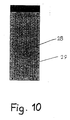
- a resistance measuring section 28 apply (Fig. 10) and it as a sensor use.
- the sensory layer 29 bends Likewise.
- stretching the meandering for example extending resistance measuring section 28, Similar to strain gauges, this bend can be detected.
Landscapes
- Keying Circuit Devices (AREA)
- Push-Button Switches (AREA)
- Transmitters (AREA)
- Relay Circuits (AREA)
- Control Of Electric Motors In General (AREA)
Applications Claiming Priority (2)
| Application Number | Priority Date | Filing Date | Title |
|---|---|---|---|
| DE19632347A DE19632347A1 (de) | 1996-08-10 | 1996-08-10 | Schalter, insbesondere Relais |
| DE19632347 | 1996-08-10 |
Publications (3)
| Publication Number | Publication Date |
|---|---|
| EP0825630A2 true EP0825630A2 (fr) | 1998-02-25 |
| EP0825630A3 EP0825630A3 (fr) | 1999-03-24 |
| EP0825630B1 EP0825630B1 (fr) | 2004-01-28 |
Family
ID=7802340
Family Applications (1)
| Application Number | Title | Priority Date | Filing Date |
|---|---|---|---|
| EP97112418A Expired - Lifetime EP0825630B1 (fr) | 1996-08-10 | 1997-07-19 | Commutateur, en particulier relais |
Country Status (7)
| Country | Link |
|---|---|
| US (1) | US5886428A (fr) |
| EP (1) | EP0825630B1 (fr) |
| JP (1) | JPH10125204A (fr) |
| KR (1) | KR19980018398A (fr) |
| CN (1) | CN1181606A (fr) |
| AT (1) | ATE258714T1 (fr) |
| DE (2) | DE19632347A1 (fr) |
Families Citing this family (11)
| Publication number | Priority date | Publication date | Assignee | Title |
|---|---|---|---|---|
| DE19623892A1 (de) * | 1996-06-06 | 1997-12-11 | Hoechst Schering Agrevo Gmbh | Substituierte Pyrazolyl-pyrazolderivate |
| US6173424B1 (en) * | 1997-12-31 | 2001-01-09 | Micron Technology, Inc. | Programmable pulse generator and method for using same |
| DE19944461C1 (de) | 1999-09-16 | 2001-01-11 | Siemens Ag | Überwachungsverfahren für ein elektromagnetisches Schaltgerät und hiermit korrespondierendes elektromagnetisches Schaltgerät |
| US6839211B2 (en) | 2002-02-21 | 2005-01-04 | Broadcom Corporation | Methods and systems for reducing power-on failure of integrated circuits |
| US7106221B2 (en) * | 2003-04-30 | 2006-09-12 | Harman International Industries, Incorporated | Capacitive touch switch system for an audio device |
| DE102004026963B4 (de) * | 2004-06-02 | 2007-04-12 | Festo Ag & Co | Ventilanordnung zur Fluidsteuerung |
| EP1949399A1 (fr) * | 2005-11-15 | 2008-07-30 | Abb Ag | Appareil de commutation electrique a magnetostriction |
| EP2053625A1 (fr) * | 2007-10-23 | 2009-04-29 | Siemens Aktiengesellschaft | Dispositif de commutation |
| EP2208215B1 (fr) * | 2007-11-15 | 2016-01-13 | Siemens Aktiengesellschaft | Dispositif de commutation et procédé de contrôle d'un relais électromagnétique |
| WO2009135500A1 (fr) * | 2008-05-06 | 2009-11-12 | Siemens Aktiengesellschaft | Dispositif de commutation |
| US8198757B2 (en) * | 2009-03-04 | 2012-06-12 | International Business Machines Corporation | Energy savings for a system powering a lower voltage device from a higher voltage power source, and wherein the system includes a power plug that outputs power to a converter, and a switch actuator |
Family Cites Families (12)
| Publication number | Priority date | Publication date | Assignee | Title |
|---|---|---|---|---|
| DE943481C (de) * | 1952-01-26 | 1956-05-24 | Siemens Ag | Elektromagnetisches Relais, Schuetz od. dgl. mit zwitverzoegerter Ansprechzeit |
| US3688135A (en) * | 1970-10-09 | 1972-08-29 | Clare & Co C P | Piezoelectrically actuated lever switch |
| US3777093A (en) * | 1972-05-25 | 1973-12-04 | R Sterns | Electromechanical relay |
| US4425524A (en) * | 1980-07-09 | 1984-01-10 | Northern Telecom Inc. | Piezoelectric switch using piezoceramic bending elements, and in particular a relay utilizing such elements |
| US4461968A (en) * | 1982-01-11 | 1984-07-24 | Piezo Electric Products, Inc. | Piezoelectric relay with magnetic detent |
| US4473859A (en) * | 1982-09-22 | 1984-09-25 | Piezo Electric Products, Inc. | Piezoelectric circuit breaker |
| US4678957A (en) * | 1986-06-24 | 1987-07-07 | General Electric Company | Piezoelectric ceramic switching devices and systems and methods of making the same |
| US4620123A (en) * | 1984-12-21 | 1986-10-28 | General Electric Company | Synchronously operable electrical current switching apparatus having multiple circuit switching capability and/or reduced contact resistance |
| DE3719298A1 (de) * | 1987-06-10 | 1988-12-22 | Bayerische Motoren Werke Ag | Verfahren zum loesen der kontakte eines klebenden relais sowie schaltungsanordnung zur durchfuehrung des verfahrens |
| DE3909261A1 (de) * | 1988-03-25 | 1989-10-05 | Gen Electric | Verfahren und system zum regeln der eingangsleistung einer elektrischen heizvorrichtung, insbesondere eines elektroherdes |
| DE4034714C2 (de) * | 1990-11-01 | 1999-11-11 | Kaco Elektrotechnik Gmbh | Kontaktträger für ein elektromagnetisches Relais |
| DE19503235A1 (de) * | 1995-02-02 | 1995-10-19 | Trenkler Gerhard Univ Prof Dr | Anordnung zum schnellen Schalten von Strömen |
-
1996
- 1996-08-10 DE DE19632347A patent/DE19632347A1/de not_active Withdrawn
-
1997
- 1997-07-19 DE DE59711251T patent/DE59711251D1/de not_active Expired - Lifetime
- 1997-07-19 EP EP97112418A patent/EP0825630B1/fr not_active Expired - Lifetime
- 1997-07-19 AT AT97112418T patent/ATE258714T1/de active
- 1997-08-05 KR KR1019970037409A patent/KR19980018398A/ko not_active Withdrawn
- 1997-08-08 JP JP9215088A patent/JPH10125204A/ja active Pending
- 1997-08-08 CN CN97117400A patent/CN1181606A/zh active Pending
- 1997-08-08 US US08/907,771 patent/US5886428A/en not_active Expired - Fee Related
Also Published As
| Publication number | Publication date |
|---|---|
| US5886428A (en) | 1999-03-23 |
| ATE258714T1 (de) | 2004-02-15 |
| KR19980018398A (ko) | 1998-06-05 |
| EP0825630B1 (fr) | 2004-01-28 |
| DE59711251D1 (de) | 2004-03-04 |
| CN1181606A (zh) | 1998-05-13 |
| JPH10125204A (ja) | 1998-05-15 |
| EP0825630A3 (fr) | 1999-03-24 |
| DE19632347A1 (de) | 1998-02-12 |
Similar Documents
| Publication | Publication Date | Title |
|---|---|---|
| EP0825630B1 (fr) | Commutateur, en particulier relais | |
| WO2001037302A1 (fr) | Commutateur de securite servant a la mise sous tension et a la mise hors tension de securite d'un recepteur electrique, en particulier d'une machine a entrainement electrique | |
| DE2805876C2 (fr) | ||
| DE102020005313B4 (de) | Elektromagnetisches Relais | |
| EP0944925A1 (fr) | Dispositif procede pour la commande d'un actionneur capacitif | |
| DE3402759A1 (de) | Stromregler fuer elektromagnetische stellantriebe | |
| EP1099260B1 (fr) | Procede et dispositif pour commander au moins un actionneur capacitif | |
| EP0986704B1 (fr) | Dispositif et procede de commande d'au moins un organe de reglage capacitif | |
| DE3934952A1 (de) | Ueberwachungsvorrichtung fuer ein verbindungselement | |
| DE4409010B4 (de) | Elektromagnetische Schaltvorrichtung | |
| DE102004030249A1 (de) | Piezoaktor-Ansteuerschaltung zur Aufladung und Entladung eines Piezoaktors | |
| EP2782793B1 (fr) | Procédé et système pour commander au moins un élément de déclenchement pour un moyen de protection de la personne | |
| DE10113801B4 (de) | Vorrichtung zum Ansteuern wenigstens eines kapazitiven Stellgliedes und Verfahren zum Betreiben einer solchen Vorrichtung | |
| DE19843621A1 (de) | Entladeschaltung für ein kapazitives Stellglied | |
| EP0831509A2 (fr) | Système d'entraínement pour commutateurs, en particulier pour relais | |
| EP3952112A1 (fr) | Procédé de détection d'un changement de position d'un élément métallique d'actionnement | |
| DE10154795B4 (de) | Verfahren und Vorrichtung zur Reduzierung des Schaltgeräusches eines elektromagnetischen Schaltgerätes | |
| DE69929947T2 (de) | Durch einen piezoelektrischen Motor angetriebener Schalter | |
| DE3532229A1 (de) | Elektronischer sicherheitstemperaturbegrenzer | |
| EP1400997A2 (fr) | Interrupteur électrique | |
| DE102004054109A1 (de) | Vorrichtung zur Ansteuerung eines kapazitiven Lastelements | |
| DE19709715A1 (de) | Vorrichtung und Verfahren zum Ansteuern wenigstens eines kapazitiven Stellgliedes | |
| DE102018009112B4 (de) | Formgedächtnisaktor mit Schutzfunktion | |
| DE102010051222B4 (de) | Sicherheitsschaltung für eine Zweihandsteuerung | |
| DE19700898B4 (de) | Schaltungsanordnung für eine Schutzeinrichtung |
Legal Events
| Date | Code | Title | Description |
|---|---|---|---|
| PUAI | Public reference made under article 153(3) epc to a published international application that has entered the european phase |
Free format text: ORIGINAL CODE: 0009012 |
|
| AK | Designated contracting states |
Kind code of ref document: A2 Designated state(s): AT CH DE FI FR GB IT LI SE |
|
| AX | Request for extension of the european patent |
Free format text: AL;LT;LV;RO;SI |
|
| PUAL | Search report despatched |
Free format text: ORIGINAL CODE: 0009013 |
|
| AK | Designated contracting states |
Kind code of ref document: A3 Designated state(s): AT BE CH DE DK ES FI FR GB GR IE IT LI LU MC NL PT SE |
|
| AX | Request for extension of the european patent |
Free format text: AL;LT;LV;RO;SI |
|
| RAP1 | Party data changed (applicant data changed or rights of an application transferred) |
Owner name: HENGSTLER GMBH |
|
| 17P | Request for examination filed |
Effective date: 19990915 |
|
| AKX | Designation fees paid |
Free format text: AT CH DE FI FR GB IT LI SE |
|
| 17Q | First examination report despatched |
Effective date: 20010808 |
|
| GRAP | Despatch of communication of intention to grant a patent |
Free format text: ORIGINAL CODE: EPIDOSNIGR1 |
|
| GRAS | Grant fee paid |
Free format text: ORIGINAL CODE: EPIDOSNIGR3 |
|
| GRAA | (expected) grant |
Free format text: ORIGINAL CODE: 0009210 |
|
| AK | Designated contracting states |
Kind code of ref document: B1 Designated state(s): AT CH DE FI FR GB IT LI SE |
|
| PG25 | Lapsed in a contracting state [announced via postgrant information from national office to epo] |
Ref country code: GB Free format text: LAPSE BECAUSE OF FAILURE TO SUBMIT A TRANSLATION OF THE DESCRIPTION OR TO PAY THE FEE WITHIN THE PRESCRIBED TIME-LIMIT Effective date: 20040128 Ref country code: FR Free format text: LAPSE BECAUSE OF FAILURE TO SUBMIT A TRANSLATION OF THE DESCRIPTION OR TO PAY THE FEE WITHIN THE PRESCRIBED TIME-LIMIT Effective date: 20040128 Ref country code: FI Free format text: LAPSE BECAUSE OF FAILURE TO SUBMIT A TRANSLATION OF THE DESCRIPTION OR TO PAY THE FEE WITHIN THE PRESCRIBED TIME-LIMIT Effective date: 20040128 |
|
| REG | Reference to a national code |
Ref country code: GB Ref legal event code: FG4D Free format text: NOT ENGLISH |
|
| REG | Reference to a national code |
Ref country code: CH Ref legal event code: EP |
|
| REF | Corresponds to: |
Ref document number: 59711251 Country of ref document: DE Date of ref document: 20040304 Kind code of ref document: P |
|
| REG | Reference to a national code |
Ref country code: CH Ref legal event code: NV Representative=s name: PATENTANWALTSBUERO JEAN HUNZIKER |
|
| PG25 | Lapsed in a contracting state [announced via postgrant information from national office to epo] |
Ref country code: SE Free format text: LAPSE BECAUSE OF FAILURE TO SUBMIT A TRANSLATION OF THE DESCRIPTION OR TO PAY THE FEE WITHIN THE PRESCRIBED TIME-LIMIT Effective date: 20040428 |
|
| GBV | Gb: ep patent (uk) treated as always having been void in accordance with gb section 77(7)/1977 [no translation filed] |
Effective date: 20040128 |
|
| PLBE | No opposition filed within time limit |
Free format text: ORIGINAL CODE: 0009261 |
|
| STAA | Information on the status of an ep patent application or granted ep patent |
Free format text: STATUS: NO OPPOSITION FILED WITHIN TIME LIMIT |
|
| 26N | No opposition filed |
Effective date: 20041029 |
|
| EN | Fr: translation not filed | ||
| PG25 | Lapsed in a contracting state [announced via postgrant information from national office to epo] |
Ref country code: IT Free format text: LAPSE BECAUSE OF NON-PAYMENT OF DUE FEES Effective date: 20090719 |
|
| PGRI | Patent reinstated in contracting state [announced from national office to epo] |
Ref country code: IT Effective date: 20110616 |
|
| PGFP | Annual fee paid to national office [announced via postgrant information from national office to epo] |
Ref country code: CH Payment date: 20110726 Year of fee payment: 15 |
|
| PGFP | Annual fee paid to national office [announced via postgrant information from national office to epo] |
Ref country code: DE Payment date: 20120925 Year of fee payment: 16 Ref country code: IT Payment date: 20120703 Year of fee payment: 16 |
|
| PGFP | Annual fee paid to national office [announced via postgrant information from national office to epo] |
Ref country code: AT Payment date: 20120801 Year of fee payment: 16 |
|
| REG | Reference to a national code |
Ref country code: CH Ref legal event code: PL |
|
| REG | Reference to a national code |
Ref country code: AT Ref legal event code: MM01 Ref document number: 258714 Country of ref document: AT Kind code of ref document: T Effective date: 20130719 |
|
| PG25 | Lapsed in a contracting state [announced via postgrant information from national office to epo] |
Ref country code: CH Free format text: LAPSE BECAUSE OF NON-PAYMENT OF DUE FEES Effective date: 20130731 Ref country code: DE Free format text: LAPSE BECAUSE OF NON-PAYMENT OF DUE FEES Effective date: 20140201 Ref country code: LI Free format text: LAPSE BECAUSE OF NON-PAYMENT OF DUE FEES Effective date: 20130731 |
|
| REG | Reference to a national code |
Ref country code: DE Ref legal event code: R119 Ref document number: 59711251 Country of ref document: DE Effective date: 20140201 |
|
| PG25 | Lapsed in a contracting state [announced via postgrant information from national office to epo] |
Ref country code: IT Free format text: LAPSE BECAUSE OF NON-PAYMENT OF DUE FEES Effective date: 20130719 Ref country code: AT Free format text: LAPSE BECAUSE OF NON-PAYMENT OF DUE FEES Effective date: 20130719 |