EP0825634B1 - Lampe fluorescente avec un film mince photocatalyseur et son procédé de fabrication - Google Patents
Lampe fluorescente avec un film mince photocatalyseur et son procédé de fabrication Download PDFInfo
- Publication number
- EP0825634B1 EP0825634B1 EP97113974A EP97113974A EP0825634B1 EP 0825634 B1 EP0825634 B1 EP 0825634B1 EP 97113974 A EP97113974 A EP 97113974A EP 97113974 A EP97113974 A EP 97113974A EP 0825634 B1 EP0825634 B1 EP 0825634B1
- Authority
- EP
- European Patent Office
- Prior art keywords
- thin film
- glass tube
- fluorescent lamp
- light
- photocatalyst
- Prior art date
- Legal status (The legal status is an assumption and is not a legal conclusion. Google has not performed a legal analysis and makes no representation as to the accuracy of the status listed.)
- Expired - Lifetime
Links
- 239000010409 thin film Substances 0.000 title claims description 159
- 239000011941 photocatalyst Substances 0.000 title claims description 115
- 238000000034 method Methods 0.000 title claims description 38
- GWEVSGVZZGPLCZ-UHFFFAOYSA-N Titan oxide Chemical compound O=[Ti]=O GWEVSGVZZGPLCZ-UHFFFAOYSA-N 0.000 claims description 116
- 239000011521 glass Substances 0.000 claims description 95
- UQSXHKLRYXJYBZ-UHFFFAOYSA-N Iron oxide Chemical compound [Fe]=O UQSXHKLRYXJYBZ-UHFFFAOYSA-N 0.000 claims description 70
- 239000004408 titanium dioxide Substances 0.000 claims description 44
- 239000010408 film Substances 0.000 claims description 34
- 239000000126 substance Substances 0.000 claims description 29
- 239000013078 crystal Substances 0.000 claims description 28
- OGIDPMRJRNCKJF-UHFFFAOYSA-N titanium oxide Inorganic materials [Ti]=O OGIDPMRJRNCKJF-UHFFFAOYSA-N 0.000 claims description 19
- 239000000203 mixture Substances 0.000 claims description 12
- LFQSCWFLJHTTHZ-UHFFFAOYSA-N Ethanol Chemical compound CCO LFQSCWFLJHTTHZ-UHFFFAOYSA-N 0.000 claims description 9
- QSHDDOUJBYECFT-UHFFFAOYSA-N mercury Chemical compound [Hg] QSHDDOUJBYECFT-UHFFFAOYSA-N 0.000 claims description 8
- 229910052753 mercury Inorganic materials 0.000 claims description 8
- 230000000704 physical effect Effects 0.000 claims description 7
- LLZRNZOLAXHGLL-UHFFFAOYSA-J titanic acid Chemical compound O[Ti](O)(O)O LLZRNZOLAXHGLL-UHFFFAOYSA-J 0.000 claims description 7
- 239000002253 acid Substances 0.000 claims description 5
- 238000003980 solgel method Methods 0.000 claims description 5
- 238000001035 drying Methods 0.000 claims description 2
- 150000002506 iron compounds Chemical class 0.000 claims description 2
- 238000012360 testing method Methods 0.000 description 45
- QGZKDVFQNNGYKY-UHFFFAOYSA-N Ammonia Chemical group N QGZKDVFQNNGYKY-UHFFFAOYSA-N 0.000 description 30
- 239000000243 solution Substances 0.000 description 30
- 230000000694 effects Effects 0.000 description 25
- 239000002245 particle Substances 0.000 description 25
- 239000000758 substrate Substances 0.000 description 23
- 239000003921 oil Substances 0.000 description 22
- 238000002834 transmittance Methods 0.000 description 21
- 241000233866 Fungi Species 0.000 description 18
- 241000894006 Bacteria Species 0.000 description 17
- 229910021529 ammonia Inorganic materials 0.000 description 15
- 238000000354 decomposition reaction Methods 0.000 description 15
- 238000001228 spectrum Methods 0.000 description 15
- 238000005259 measurement Methods 0.000 description 14
- JZQOJFLIJNRDHK-CMDGGOBGSA-N alpha-irone Chemical compound CC1CC=C(C)C(\C=C\C(C)=O)C1(C)C JZQOJFLIJNRDHK-CMDGGOBGSA-N 0.000 description 12
- 238000006243 chemical reaction Methods 0.000 description 12
- 239000007789 gas Substances 0.000 description 12
- 229910000859 α-Fe Inorganic materials 0.000 description 12
- 238000004332 deodorization Methods 0.000 description 11
- XLYOFNOQVPJJNP-UHFFFAOYSA-N water Substances O XLYOFNOQVPJJNP-UHFFFAOYSA-N 0.000 description 10
- 229910001868 water Inorganic materials 0.000 description 10
- 230000000844 anti-bacterial effect Effects 0.000 description 9
- 239000011230 binding agent Substances 0.000 description 8
- 230000003247 decreasing effect Effects 0.000 description 8
- 230000000855 fungicidal effect Effects 0.000 description 8
- 239000000463 material Substances 0.000 description 8
- 238000002441 X-ray diffraction Methods 0.000 description 7
- 239000000428 dust Substances 0.000 description 7
- 230000001954 sterilising effect Effects 0.000 description 7
- IJGRMHOSHXDMSA-UHFFFAOYSA-N Atomic nitrogen Chemical compound N#N IJGRMHOSHXDMSA-UHFFFAOYSA-N 0.000 description 6
- CURLTUGMZLYLDI-UHFFFAOYSA-N Carbon dioxide Chemical compound O=C=O CURLTUGMZLYLDI-UHFFFAOYSA-N 0.000 description 6
- LYCAIKOWRPUZTN-UHFFFAOYSA-N Ethylene glycol Chemical compound OCCO LYCAIKOWRPUZTN-UHFFFAOYSA-N 0.000 description 6
- 238000005202 decontamination Methods 0.000 description 6
- 230000003588 decontaminative effect Effects 0.000 description 6
- 238000005070 sampling Methods 0.000 description 6
- 239000005361 soda-lime glass Substances 0.000 description 6
- 238000004659 sterilization and disinfection Methods 0.000 description 6
- 239000010936 titanium Substances 0.000 description 6
- 229910052719 titanium Inorganic materials 0.000 description 6
- 240000008415 Lactuca sativa Species 0.000 description 5
- RTAQQCXQSZGOHL-UHFFFAOYSA-N Titanium Chemical compound [Ti] RTAQQCXQSZGOHL-UHFFFAOYSA-N 0.000 description 5
- 238000000576 coating method Methods 0.000 description 5
- 230000008569 process Effects 0.000 description 5
- 235000012045 salad Nutrition 0.000 description 5
- 238000001179 sorption measurement Methods 0.000 description 5
- 238000009825 accumulation Methods 0.000 description 4
- 239000007864 aqueous solution Substances 0.000 description 4
- QVGXLLKOCUKJST-UHFFFAOYSA-N atomic oxygen Chemical compound [O] QVGXLLKOCUKJST-UHFFFAOYSA-N 0.000 description 4
- 239000011248 coating agent Substances 0.000 description 4
- 125000002887 hydroxy group Chemical group [H]O* 0.000 description 4
- 239000001301 oxygen Substances 0.000 description 4
- 229910052760 oxygen Inorganic materials 0.000 description 4
- 230000003405 preventing effect Effects 0.000 description 4
- 238000012545 processing Methods 0.000 description 4
- 230000005476 size effect Effects 0.000 description 4
- VXUYXOFXAQZZMF-UHFFFAOYSA-N titanium(IV) isopropoxide Chemical compound CC(C)O[Ti](OC(C)C)(OC(C)C)OC(C)C VXUYXOFXAQZZMF-UHFFFAOYSA-N 0.000 description 4
- 229910003145 α-Fe2O3 Inorganic materials 0.000 description 4
- MHAJPDPJQMAIIY-UHFFFAOYSA-N Hydrogen peroxide Chemical compound OO MHAJPDPJQMAIIY-UHFFFAOYSA-N 0.000 description 3
- 239000001569 carbon dioxide Substances 0.000 description 3
- 229910002092 carbon dioxide Inorganic materials 0.000 description 3
- 238000004140 cleaning Methods 0.000 description 3
- 238000011109 contamination Methods 0.000 description 3
- 230000005284 excitation Effects 0.000 description 3
- 229910052757 nitrogen Inorganic materials 0.000 description 3
- 230000003647 oxidation Effects 0.000 description 3
- 238000007254 oxidation reaction Methods 0.000 description 3
- 230000001699 photocatalysis Effects 0.000 description 3
- XKRFYHLGVUSROY-UHFFFAOYSA-N Argon Chemical compound [Ar] XKRFYHLGVUSROY-UHFFFAOYSA-N 0.000 description 2
- 239000004215 Carbon black (E152) Substances 0.000 description 2
- GRYLNZFGIOXLOG-UHFFFAOYSA-N Nitric acid Chemical compound O[N+]([O-])=O GRYLNZFGIOXLOG-UHFFFAOYSA-N 0.000 description 2
- 238000001237 Raman spectrum Methods 0.000 description 2
- VYPSYNLAJGMNEJ-UHFFFAOYSA-N Silicium dioxide Chemical compound O=[Si]=O VYPSYNLAJGMNEJ-UHFFFAOYSA-N 0.000 description 2
- 238000010521 absorption reaction Methods 0.000 description 2
- -1 alcohol amines Chemical class 0.000 description 2
- 230000005540 biological transmission Effects 0.000 description 2
- 239000011203 carbon fibre reinforced carbon Chemical group 0.000 description 2
- 239000012531 culture fluid Substances 0.000 description 2
- 238000010586 diagram Methods 0.000 description 2
- 229930195733 hydrocarbon Natural products 0.000 description 2
- 150000002430 hydrocarbons Chemical class 0.000 description 2
- MVFCKEFYUDZOCX-UHFFFAOYSA-N iron(2+);dinitrate Chemical compound [Fe+2].[O-][N+]([O-])=O.[O-][N+]([O-])=O MVFCKEFYUDZOCX-UHFFFAOYSA-N 0.000 description 2
- 230000031700 light absorption Effects 0.000 description 2
- 230000007246 mechanism Effects 0.000 description 2
- VUZPPFZMUPKLLV-UHFFFAOYSA-N methane;hydrate Chemical compound C.O VUZPPFZMUPKLLV-UHFFFAOYSA-N 0.000 description 2
- 238000002156 mixing Methods 0.000 description 2
- 229910017604 nitric acid Inorganic materials 0.000 description 2
- 238000013032 photocatalytic reaction Methods 0.000 description 2
- 238000012643 polycondensation polymerization Methods 0.000 description 2
- 230000009467 reduction Effects 0.000 description 2
- 229910052814 silicon oxide Inorganic materials 0.000 description 2
- VHUUQVKOLVNVRT-UHFFFAOYSA-N Ammonium hydroxide Chemical compound [NH4+].[OH-] VHUUQVKOLVNVRT-UHFFFAOYSA-N 0.000 description 1
- 206010020751 Hypersensitivity Diseases 0.000 description 1
- CBENFWSGALASAD-UHFFFAOYSA-N Ozone Chemical compound [O-][O+]=O CBENFWSGALASAD-UHFFFAOYSA-N 0.000 description 1
- 238000001069 Raman spectroscopy Methods 0.000 description 1
- 150000004703 alkoxides Chemical class 0.000 description 1
- 208000026935 allergic disease Diseases 0.000 description 1
- 230000007815 allergy Effects 0.000 description 1
- 238000004458 analytical method Methods 0.000 description 1
- 229910052786 argon Inorganic materials 0.000 description 1
- 230000004888 barrier function Effects 0.000 description 1
- 230000008901 benefit Effects 0.000 description 1
- 239000003054 catalyst Substances 0.000 description 1
- 230000007423 decrease Effects 0.000 description 1
- 230000000593 degrading effect Effects 0.000 description 1
- 230000001877 deodorizing effect Effects 0.000 description 1
- 238000001514 detection method Methods 0.000 description 1
- 201000010099 disease Diseases 0.000 description 1
- 208000037265 diseases, disorders, signs and symptoms Diseases 0.000 description 1
- 238000011156 evaluation Methods 0.000 description 1
- 238000002474 experimental method Methods 0.000 description 1
- 238000004817 gas chromatography Methods 0.000 description 1
- 238000010438 heat treatment Methods 0.000 description 1
- XLYOFNOQVPJJNP-UHFFFAOYSA-M hydroxide Chemical compound [OH-] XLYOFNOQVPJJNP-UHFFFAOYSA-M 0.000 description 1
- 239000011261 inert gas Substances 0.000 description 1
- 239000012212 insulator Substances 0.000 description 1
- 230000001678 irradiating effect Effects 0.000 description 1
- 229910052743 krypton Inorganic materials 0.000 description 1
- DNNSSWSSYDEUBZ-UHFFFAOYSA-N krypton atom Chemical compound [Kr] DNNSSWSSYDEUBZ-UHFFFAOYSA-N 0.000 description 1
- 229910052754 neon Inorganic materials 0.000 description 1
- GKAOGPIIYCISHV-UHFFFAOYSA-N neon atom Chemical compound [Ne] GKAOGPIIYCISHV-UHFFFAOYSA-N 0.000 description 1
- 230000007935 neutral effect Effects 0.000 description 1
- 230000001590 oxidative effect Effects 0.000 description 1
- 239000002243 precursor Substances 0.000 description 1
- 238000003672 processing method Methods 0.000 description 1
- 230000003134 recirculating effect Effects 0.000 description 1
- 238000004611 spectroscopical analysis Methods 0.000 description 1
- 230000004083 survival effect Effects 0.000 description 1
- 208000024891 symptom Diseases 0.000 description 1
- 230000002195 synergetic effect Effects 0.000 description 1
- 238000012546 transfer Methods 0.000 description 1
- 229910052724 xenon Inorganic materials 0.000 description 1
- FHNFHKCVQCLJFQ-UHFFFAOYSA-N xenon atom Chemical compound [Xe] FHNFHKCVQCLJFQ-UHFFFAOYSA-N 0.000 description 1
Images





Classifications
-
- H—ELECTRICITY
- H01—ELECTRIC ELEMENTS
- H01J—ELECTRIC DISCHARGE TUBES OR DISCHARGE LAMPS
- H01J61/00—Gas-discharge or vapour-discharge lamps
- H01J61/02—Details
- H01J61/30—Vessels; Containers
- H01J61/35—Vessels; Containers provided with coatings on the walls thereof; Selection of materials for the coatings
-
- A—HUMAN NECESSITIES
- A61—MEDICAL OR VETERINARY SCIENCE; HYGIENE
- A61L—METHODS OR APPARATUS FOR STERILISING MATERIALS OR OBJECTS IN GENERAL; DISINFECTION, STERILISATION OR DEODORISATION OF AIR; CHEMICAL ASPECTS OF BANDAGES, DRESSINGS, ABSORBENT PADS OR SURGICAL ARTICLES; MATERIALS FOR BANDAGES, DRESSINGS, ABSORBENT PADS OR SURGICAL ARTICLES
- A61L9/00—Disinfection, sterilisation or deodorisation of air
- A61L9/16—Disinfection, sterilisation or deodorisation of air using physical phenomena
- A61L9/18—Radiation
- A61L9/20—Ultraviolet radiation
- A61L9/205—Ultraviolet radiation using a photocatalyst or photosensitiser
Definitions
- the invention relates to a fluorescent lamp with a coating of thin film photocatalyst which is provided in a space such as a resident space, a vehicle, etc., requiring lighting equipment for lighting the space, purifying air in the space, and cutting off ultraviolet radiated from the fluorescent lamp.
- a lamp on a surface of which a titanium oxide film is coated, is disclosed in the DE 4410476 A1.
- malodorous substances in air can be decomposed and removed by oxidation and reduction initiated by pairs of an electron and a hole generated in the titanium oxide film on which light is irradiated from the inside of the lamp.
- JP-A-07/100378 describes a photocatalyst which is produced by coating a base plate with a titania sol prepared from the alkoxide of titanium and alcohol amines etc., then heating up the base plate gradually from room temperature up to the final temperature of 600 to 700 °C, thereby baking the titania sol.
- the resulting titanium oxide film contains crystals having the anatase crystal structure and crystals of the rutile structure.
- An object of the invention is to provide a fluorescent lamp with a coating of thin film photocatalyst on the outer surface, having higher activity in deodorizing, sterilizing and decontaminating effects than the above-mentioned lamp.
- Another object of the invention is to present a method of creating a fluorescent lamp with a thin film photocatalyst to attain the above objectives.
- the present invention provides a fluorescent lamp including a light transmissive glass tube, a thin film fluorescent substance applied on an inside wall of the glass tube, bases and pins provided at the both sides of the glass tube, mercury and buffer gas enclosed in the glass tube, and a light transmissive and transparent thin film photocatalyst made of one of titanium oxide having anatase-type crystal structure or iron oxide having alpha-crystal structure ⁇ -Fe 2 O 3 , applied on an outside surface of the glass tube.
- the present invention provides a fluorescent lamp including a light transmissive glass tube, a thin film fluorescent substance applied on an inside wall of the glass tube, bases and pins provided at the both sides of the glass tube, and mercury and buffer gas enclosed in the glass tube, the fluorescent lamp comprising:
- the thickness of the thin film photocatalyst made of anatase titanium dioxide is in a range of 0.02 ⁇ m to 2 ⁇ m, or that the thickness of the thin film photocatalyst made of alpha iron oxide is in a range of 0.01 ⁇ m to 0.1 ⁇ m. If the thickness of the photocatalyst is too thin below these ranges, the effects of deodorization, sterilization and decontamination can not be sufficiently obtained, and if the thickness is too large beyond these ranges, the light transmittance is rather degraded and this results in the loss of function as a lamp.
- a fluorescent lamp according to the present invention is different from a fluorescent lamp disclosed in DE 4 410 476 A1, in which a titanium oxide film with unspecified crystal structure is coated on a surface of the lamp, whereas an anatase-type titanium dioxide is coated on an outside surface of the fluorescent lamp in the present invention.
- a crystal structure is not disclosed in that document, the structure of the titanium oxide film was examined and found to be amorphous and not the anatase-type crystal structure we have in our invention.
- the thin film photocatalyst is prepared so that electrons and holes generated within the thin film photocatalyst by light irradiated on the film can rapidly move throughout the film, which is realized by improving light transmission and transparency of the film.
- a highly light-transmissive and transparent photocatalyst is obtained, for example, by preparing the film so that the crystal of anatase titanium dioxide or alpha iron oxide are two-dimensionally and continuously structured to form a sheet of thin film.
- the above-mentioned thin film photocatalyst can be formed by our method based on sol-gel process.
- the film transmits light with a wave length range of 290 nm - 1200 nm, and transmits more than 90 % of light with a wave length range of 290 nm - 750 nm.
- the present invention provides a method to produce a fluorescent lamp including a light transmissive glass tube, a thin film fluorescent substance applied on an inside wall of the glass tube, bases and pins provided at the both sides of the glass tube, and mercury and buffer gas enclosed in the glass tube, the method comprising the steps of:
- the sol solution made of a mixture of titanium alkoxide, acid and alcohol is used to form the thin film titanium dioxide, and also the sol solution made of a mixture of iron compound, acid and alcohol is used to form the thin film alpha iron oxide.
- the temperature for baking the sol solution adhered to the outside wall of the glass tube is in a rang of 450 - 600 °C in the case of forming an thin film anatase-type titanium oxide, and in a range of 560-770 °C in the case of forming an alpha iron oxide.
- a light-transmissive and transparent thin film photocatalyst is formed on an outside surface of a glass tube inside of which a light source exists. Therefore, although light is irradiated on the thin film photocatalyst from the opposite side of the reaction surface, since the distance between the light source and the photocatalyst is very short, the feeble light energy of the fluorescent lamp is maximally utilized.
- light transmissive means that light of a wave length range of 290 nm - 1200 nm in the natural light can be transmitted. Therefore, it is necessary that light irradiated on a surface of the thin film photocatalyst can pass through the film and reach the outside front surface of the film. It is needless to say that the glass tube itself is transparent since the above-mentioned lamp is a fluorescent lamp.
- the word transparent means that an object on one side of the thin film photocatalyst is visible by viewing from the other side of the film with a naked-eye.
- a transparent substance should be able to transmit light of a wave length range with 290 nm - 750 nm.
- a light of the above mentioned wave length range is the light which can be sensed by a naked-eye.
- light radiated from a fluorescent lamp has wave lengths within the above-mentioned range.
- Photocatalyst is a special catalyst that can initiate chemical reactions at room temperature by absorbing light energy. If light is irradiated on photocatalyst, electrons are excited from a valence band to a conduction band beyond a band gap characteristic of the photocatalytic material, and a pair of an electron (e - ) and a hole (h + ) are generated. That is, in the light irradiation, if photons with the larger than the energy band gap, that is, a shorter wave length than that corresponding to the bang gap energy ( the critical wave length ), are irradiated on the photocatalyst, the above-mentioned electron excitation occurs.
- the critical wave length is about 400 nm in case of anatase-type titanium dioxide, and about 540 nm in alpha iron oxide.
- the photon generation rate per unit irradiation area and unit time is proportional to the energy intensity of irradiated light having a wave length within the excitation wave length range.
- the electrons and holes generated by the photon-excitation produces various kinds of active species at the surface of the photocatalyst.
- the electrons react the oxygen from the air, and produce active oxygen (O 2 - ).
- the holes react with water from the air, and produce protons ( H + ) and oxygen molecules.
- active ozone O 3 -
- hydroxide ion OH -
- hydroxide radical OH •
- a hydrogen peroxide molecule H 2 O 2
- the generation rate of the above-mentioned active species per unit irradiation area and unit time is proportional to the generation rate of electrons and holes, that is, the generation rate of photons
- the decomposition rate of harmful substances is proportional to the above-mentioned generation rates.
- Fig. 1 shows a longitudinal cross-section of a fluorescent lamp of an embodiment according to the present invention.
- Fig. 2 shows a cross-section of the fluorescent lamp viewed from the position II - II in Fig. 1.
- Fig. 3 is an illustration for explaining operations and effects of the fluorescent lamp of the present invention.
- Fig. 4 is a laser Raman spectrum showing the crystal structure of a thin film titanium oxide applied on a glass substrate.
- Fig. 5 is a X-ray diffraction spectrum of the thin film titanium oxide.
- Fig. 6(A) and 6(B) are a processed spectrum of the spectrum shown in Fig. 5 and the analyzed results of the processed spectrum, respectively.
- Fig. 7 is a graph showing the light transmittance of the thin film titanium oxide applied on a glass substrate.
- Fig. 8 is a graph showing the ultraviolet cut percentage of the thin film titanium oxide applied on a glass substrate.
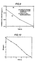
- Fig. 9 is a graph showing the decontamination effects ( decomposition of salad oil ) of the thin film titanium oxide applied on a glass substrate.
- Fig. 10 is a graph showing the deodorization effects ( decomposition of ammonia ) of the thin film titanium oxide applied on a glass substrate.
- Fig. 11 is a graph showing the sterilization effects ( sterilization of bacteria and fungi in the air) of the thin film titanium oxide applied on a glass substrate.
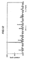
- Fig. 12 is a processed X-ray diffraction spectrum of the thin film iron oxide applied on a glass substrate.
- Fig. 13 is a graph showing the light transmittance of a thin film iron oxide applied on a glass substrate.
- Fig. 14 is a graph showing the visible light cut percentage of the thin film iron oxide applied on a glass substrate.
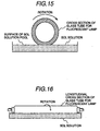
- Fig. 15 a side cross-sectional view showing the thin film photocatalyst forming process by using a contact rotation method.
- Fig. 16 a longitudinal cross-sectional view showing the thin film photocatalyst forming process by using a contact rotating method.
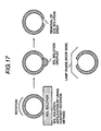
- Fig. 17 is a diagram for explaining the processing states of the thin film photocatalyst formed by using the contact rotating method.
- Fig. 18 is a composition diagram of a reaction testing apparatus for examining the bactericidal and fungicidal activity and the deodorization effect of the fluorescent lamp with photocatalyst of the embodiment according to the present invention.
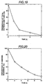
- Fig. 19 is a graph showing the relation between the percentage survival of total bacteria and fungi, and the laps of time, which indicates the sterilization effects of the fluorescent lamp with photocatalyst of the embodiment according to the present invention.
- Fig. 20 is a graph showing results of an experiment for testing the decomposition of ammonia, which indicates the deodorization effects of the fluorescent lamp with photocatalyst of the embodiment according to the present invention.
- FIG. 1 A fluorescent lamp of an embodiment according to they present invention is shown in Fig. 1 and Fig. 2.
- Fig. 2 is a cross-section of the fluorescent lamp viewed from the position II - II in Fig. 1.
- the fluorescent lamp possesses a thin film photocatalyst 2 on an outside surface of a straight tube type glass tube 1.
- a fluorescent material film 3 is coated on an inside surface of the glass tube 1.
- mercury and buffer gas In the glass tube 1, mercury and buffer gas is enclosed.
- the electric discharge is generated by electrically connecting the lamp to a power source via bases 5 and pins 6, and the mercury radiates ultraviolet.
- the fluorescent material film 3 receives the radiated ultraviolet and emits light.
- As the buffer gas inert gas such as neon, argon, krypton, xenon, and so forth, is used.
- the thin film photocatalyst 2 absorbs the ultraviolet radiated from the fluorescent lamp and the other ultraviolet irradiated on a surface of the photocatalyst 2, and decomposes malodorous substances, bacteria and fungi or oil substances which are deposited on the surface of the fluorescent lamp, into such safe chemicals as carbon dioxide, nitrogen and water.
- the energy of the light radiated from the thin film fluorescent material 3 can be efficiently utilized.
- a feeble light source such as a fluorescent lamp
- the above-mentioned composition of the lamp can use the most of the light radiated from the light source.
- the decomposition of harmful substances such as malodorous substances is caused by the light irradiated on the back surface of the thin film photocatalyst. Consequently, the light which transmitted through the thin film photocatalyst, can further go to the outside of the fluorescent lamp.
- the above-mentioned mechanism of light passing through the thin film photocatalyst for example, by providing two or more fluorescent lamps neighboring each other, multiple light receptions and excitations can be realized among thin film photocatalysts of plural fluorescent lamps. Thus, a synergistic effect can be realized.
- the whole of the thin film photocatalyst is made of anatase-type titanium dioxide or alpha iron oxide, and crystallites composing the whole of the thin film are two-dimensionally and continuously arranged to be a thin sheet of the photocatalyst.
- a conventional thin film photocatalyst is formed by adhering photocatalyst particles with a binder, and this is distinctly different from the thin film photocatalyst of the present invention, in which no binder is used.
- the photocatalyst 2 can be excited in the thin film and at a surface of the thin film.
- the light passes through the thin film photocatalyst, the light excites the photocatalyst and produces pairs of an electron and a hole, in its inside region and at its surface.
- the produced pairs of an electron and a hole in the inside of the thin film photocatalyst 2 rapidly move to the surface of the thin film.
- the pairs of an electron and a hole generate various kinds of active species, and the generated active species chemically decompose harmful substances.
- the thin film photocatalyst of the present invention crystallites of the photocatalyst are tightly connected to each other, and two-dimensionally and continuously arranged, which forms one thin sheet of the photocatalyst. Therefore, light can pass through the film without absorption in other material, and be effectively used. Thus, the efficiency of the photocatalyst is remarkably improved in the thin film photocatalyst of the present invention.
- the laminated photocatalyst particle layer it is preferred to use smaller particles of photocatalyst to increase the surface area of the particles per unit volume.
- the band gap of photocatalyst increases by a quantum size effect if a size of particle is decreased below a critical size, the photocatalyst is excited only by ultraviolet of a shorter wave length having higher energy. Therefore, in the case that photocatalyst is excited by a light source such as a fluorescent lamp in which the radiated light has a comparatively low photon energy in the ultraviolet region, or light ray from the sun, the quantum size effect disadvantageously affects the laminated particle layer type photocatalyst.
- the critical size of a particle is 10 nm - 20 nm. If particles or grains of a smaller size than the critical size are used, although the transparency of the laminated particle layer can be increased, it is not preferable because of the above-mentioned problem of the quantum size effect. Thus, the thin film photocatalyst of the present invention is more advantageous since the quantum size effect does not become a problem.
- titanium tetra isopropoxide was hydrolyzed by adding a mixture solution of acid and alcohol to a mixture solution of titanium tetra isopropoxide and alcohol, and titanium sol solution was obtained by processing the obtained titanium hydroxide.
- the titanium sol solution was coated on a glass substrate of the same composition ( soda-lime glass ) as that of a glass tube used to a fluorescent lamp, and heated to about 500 °C, and dried and baked at the temperature.
- soda-lime glass soda-lime glass
- condensation polymerization between hydroxyl groups of titanium hydroxide and hydroxyl groups existing at the surface of the glass substrate proceeded, and chemical bonding between titanium dioxide and silicon oxide which is the dominant component of soda-lime glass also proceeded. Consequently, a light transmissive and transparent thin film titanium dioxide was formed on the surface of the glass substrate.
- the crystal structure of the thin film titanium dioxide of which the thickness is 530 nm was the structure of 100 % anatase-type crystal.
- the main peak positions ( 640, 518, 396, and 197 cm -1 ) in the obtained spectrum coincide with the peak positions ( 640, 515, 400, and 197 ) in the spectrum of a single crystal anatase-type titanium dioxide, which is reported in a paper Proc. Roy. Soc. ( London ) A, vol.
- the bulk crystal structure of a sample of the film formed by the above-mentioned processing method is the structure of 100 % anatase-type crystal. From the peak positions of the intensity pair 2 ⁇ spectrum shown in Fig. 5 and the analysis results of the peaks shown in Figs. 6(A) and 6(B), the peaks peculiar to the anatase-type crystal structure, that is, peaks at the intensity pair 2 ⁇ positions of 25.35, 37.9, 48.15, and 53.95, were observed. The size of a crystallite in the film sample was analyzed by the X-ray diffraction method, and determined to be 34.6 nm.
- the light transmittance of the film formed by the above-mentioned method was measured by using a light measurement apparatus having a light source of a fluorescent lamp which radiates light having a light spectrum of the wave length range 290 nm - 750 nm.
- the light was irradiated on one surface of a test piece, and the light passing through the test piece was detected from the opposite side.
- the test piece was composed such that a thin film titanium dioxide was formed on each of the both surfaces of a glass substrate. Therefore, two thin films of titanium dioxide, each thin film having the thickness of 530 nm, sandwich the glass substrate.
- the measurement results showed that 98.8 % - 99.9 % of the irradiated light can pass through each thin film, and the intensity of the irradiated light was scarcely decreased by the thin films of titanium dioxide.
- the above-mentioned value for one thin film of the thickness of 530 nm was calculated, based on the measured light transmittance of the test piece composed of a glass substrate and two thin films of titanium dioxide sandwiching the glass substrate and the measured light transmittance of only the glass substrate.
- the measured light transmittance of the thin film indicated the high value, independently of the light energy intensity irradiated on the film.
- the light transmittance value of 99.9 % was obtained under the irradiation condition in which the light having the light energy intensity ( 22.7 mW/cm 2 ) at an outside surface of the fluorescent lamp was irradiated on the test piece, and the light irradiation condition is almost the same as the condition of the case that a thin film titanium dioxide is formed on an outside surface of a fluorescent lamp.
- the light transmittance value of 98.8 % was obtained under the irradiation condition in which the light having the light energy intensity 0.69 mW/cm 2 at a position remote from an outside surface of the fluorescent lamp was irradiated on the test piece. Both of the obtained light transmittance values were high. Therefore, it was shown that the light transmittance of the thin film titanium dioxide is sufficiently high at least within the light energy intensity range of 0.69 - 22,7 mW/cm 2 .
- the relation between the light transmittance and the light energy intensity is shown in Fig. 7. In the figure, effects of the thickness on the light transmittance are also shown.
- the film has the high transmittance value of 96.3 % even under the conditions of the 740 nm thickness and the 0.69 mW/cm 2 irradiated light energy intensity.
- a thin film titanium dioxide shows double effects of absorbing and cutting ultraviolet rays of a less than 400 nm wave length corresponding to the band gap of the titanium dioxide, and of being excited by the absorbed ultraviolet light.
- the measurement results of the light cut percentage for various wave lengths included in the light at a surface of a fluorescent lamp are shown in Fig. 8. In the measurement, the above-mentioned test piece was used. It is shown by curve ( a ) in Fig. 8 that the light having a 365 nm wave length corresponding to the energy higher than the band gap is absorbed.
- the deodorization effect of the thin film photocatalyst was measured by using the test piece used in the above-mentioned test.
- the measurement was carried out in a test system made of a closed-circulation system.
- inert material was used to make an inside wall of a reactor so as not to adsorb a very small quantity of substances to the inside wall, and gas contained in the reactor was stirred by a bellows circulation pump in which oil is not used to avoid contamination by oil.
- a sample holder for holding the test piece was provided at the central part of the reactor, and light was irradiated on the test piece through a special light-transmissive window from the outside.
- the gas contained in the reactor was lead to an atmospheric gas measurement device ( apparatus for sending atmospheric gas to a gas chromatography mass spectrometer system ) via a sampling valve, and the concentration time-changes of harmful substances in the gas contained inside the reactor were traced.
- an atmospheric gas measurement device apparatus for sending atmospheric gas to a gas chromatography mass spectrometer system
- the concentration time-changes of harmful substances in the gas contained inside the reactor were traced.
- Fig. 10 the measurement results in decomposition reactions of ammonia were shown when light from a fluorescent lamp was irradiated on the test piece.
- the total light energy intensity of the irradiated light at a surface of the test piece was 1.5 mW/cm 2
- the light energy intensity of a light component of a 365 nm wave length in the irradiated light was 20 ⁇ W/cm 2 .
- the bactericidal and fungicidal activity of the thin film photocatalyst was tested by using the same test piece and the same test system. Tested bacteria and fungi were those living in the air of a room. The same light source of the fluorescent lamp was used, and the total light energy intensity of light at the surface of the test piece and the light energy intensity of the light of the 365 nm wave length were the same as those of the light used in the above-mentioned test. The bactericidal and fungicidal activity was measured by a method in which the room air was enclosed in the test system, and after the photocatalytic reactions in the test system continued for a definite time, the bacteria and fungi in the enclosed air were sampled for a definite time.
- the sampling was repeated periodically.
- the sampling was carried out by a by-pass method in which a new sampler was provided in the circulation system in each time.
- a culture fluid was fed into the sampler, and after the bacteria and fungi in the sampler were cultivated for 48 hours in an incubator in which the temperature was kept at 30 °C, the number of fungus colonies was counted.
- the results of the test is shown in Fig. 11.
- the number of colonies counted at the start time of the test was 9, and the number of colonies counted at 4 hours after the start time was 0 which means that all detectable bacteria and fungi contained in the enclosed air died after 4 hours from the start of the test.
- the thin film photocatalyst has a bactericidal and fungicidal effect. Furthermore, the same test piece which was turned upward, was immersed below and in the vicinity of a surface of water containing mold bacteria and fungi, and light of a fluorescent lamp was irradiated on the test piece. It was confirmed that the mold bacteria and fungi decreased remarkably.
- Sol solution was made by mixing iron nitrate, ethylene glycol and nitric acid. After the sol solution was coated on a surface of a glass substrate of the same composition as that of a soda-lime glass tube used to a fluorescent lamp, a thin film iron oxide was formed by a sol-gel processing method in which the coated sol solution were dried as the temperature is increased from 100 °C, and baked at 600 °C. By the above-mentioned processing, a colored and very light-transmissive thin film iron oxide was formed.
- the formed light-transmissive iron oxide of which the thickness is 50 nm is alpha iron oxide ( ⁇ -Fe 2 O 3 ).
- the spectrum has four peaks particular to alpha iron oxide, that is, peaks at 2 ⁇ values of 51.9, 38.1, 34.0 and 33.4.
- the thin film iron oxide transmit light of a wave length range of 290-1200 nm, similar to the thin film titanium dioxide.
- the thin film iron oxide In the light transmittance measurement of the thin film iron oxide, a light energy intensity measurement apparatus was used, in which a fluorescent lamp radiating light of a wave length range of 290 nm - 750 nm, was provided as a light source. From the measurement results, it was confirmed that the thin film ⁇ -Fe 2 O 3 had a more than 75 % light transmittance which was almost independent of the energy intensity of the irradiated light, as shown in Fig. 13. In the case of the irradiated light energy intensity of 20.8 mW/cm 2 at an outside surface of the fluorescent lamp, the thin film iron oxide of the thickness of 50 nm had the light transmittance of 75.8 %. In measuring the light transmittance of the thin film as increasing the thickness of the thin film to 90 nm and 260 nm, the light transmittance decreased to 64.8 % and 38.9 %.
- the thin film iron oxide has the physical property of absorbing light of a less than 540 nm wave length corresponding to its band gap. As shown in Fig. 14, the thin film iron oxide absorbs visible light of 405 nm and 436 nm wave lengths, besides ultraviolet of a 365 nm wave length, and is excited by the absorbed light. The iron oxide is different from the titanium in the above-mentioned light absorption property of the visible light.
- the light cut percentage of a 365 nm ultraviolet increased to 66.7 %, 83.8 % and 100 % , as the thickness of the thin film increased to 50 nm, 90 nm and 260 nm.
- An outside surface of a soda-lime glass tube used for a fluorescent lamp was horizontally held and contacted to a surface of the same sol solution as the solution used in the embodiment 1, which was contained in a vessel, as shown in Fig. 15 and Fig. 16.
- the glass tube of which the outside surface was contacted to a surface of a pool of the sol solution was rotated at a constant speed by one rotation, and the rotation was stopped.
- the outside surface of the glass tube was lifted from the surface of the sol solution pool.
- droplets of the solution dripping from the adhered sol solution on the glass tube were formed, and the droplets caused a non-uniformity in the thickness of the coated sol solution.
- the adhered sol solution was baked at 500 °C.
- condensation polymerization between hydroxyl groups of titanium hydroxide and hydroxyl groups existing at the surface of the glass substrate proceeded, and strong chemical bonding of titanium dioxide and silicon oxide which is a dominant component of soda-lime glass also proceeded.
- a high light transmissive and transparent thin film titanium dioxide was obtained on the outside surface of the glass tube.
- the thickness of the thin film titanium dioxide formed on the outside surface of the glass tube used for the fluorescent lamp was measured by using a sectional image of the thin film and the glass obtained by a scanning electron microscope, to be 370 nm ⁇ 10 nm which indicates the highly uniform thickness. It was determined by analyzing a measured X-ray diffraction pattern that the crystal structure of the thin film has the 100 % anatase-type titanium dioxide, likely to the measurement results in the embodiment 1. The d value at the intensity pair 2 ⁇ of 25.35 was 3.5105 characteristic of anatase-type titanium dioxide.
- the light transmittance of the above-mentioned anatase type titanium dioxide was measured to be 96.3 % to light having a spectrum of a 200 - 1200 nm wave length range, and 97.6 % to light having a spectrum of a 200 - 700 nm wave length range.
- UVA near ultraviolet which has a 325 nm - 388 nm wave length range
- mainly includes ultraviolet of a 365 nm wave length mainly includes ultraviolet of a 365 nm wave length
- the absorption of about 20 % of the ultraviolet was observed. It was confirmed that the absorption of light did not occur in the case of irradiation with light having a wave length in a range of 405 nm - 436 nm outside the ultraviolet range including light of a wave length shorter than 400 nm.
- the bactericidal and fungicidal activity to bacteria and fungi in the air of a room, of a fluorescent lamp with a thin film photocatalyst formed by the above-mentioned process was tested by using a reaction testing apparatus in which a fluorescent lamp with the film photocatalyst was provided and turned on, and a part of the air including bacteria and fungi was enclosed.
- the reaction testing apparatus was a closed gas circulation system.
- the activity was confirmed by a method in which after the photocatalytic reactions of the enclosed air were continued for a definite time, the bacteria and fungi included in the enclosed air were sampled for a definite time.
- the sampling was carried out by a by-pass method in which a new sampler was provided in the circulation system in each sampling.
- a culture fluid was fed into the sampler, and after the sampler were cultivated for 72 hours in an incubator in which the temperature was kept at 30 °C, the number of colonies was counted. As shown in Fig. 19 indicating test results, the surviving percentage decreased to 0 at about 3 hours after the light irradiation on the thin film photocatalyst by switching on the fluorescent lamp with the photocatalyst coating. Therefore, the bactericidal and fungicidal effect caused by the fluorescent lamp with the thin film photocatalyst was clearly shown.
- the light radiated from the fluorescent lamp passed through the glass tube and generated various kinds of active species at an outside surface of the thin film photocatalyst as the light was passed through the thin film, and the generated active species sterilized the bacteria and fungi in the air.
- the deodorization effect of a fluorescent lamp with the thin film photocatalyst was confirmed by using the above-mentioned reaction testing apparatus.
- the air contained in the testing apparatus was exhausted and the testing apparatus was evacuated, then the air containing ammonia by 10 ppm was fed into the testing apparatus.
- the concentration of ammonia in the apparatus was measured by a gas detection system at a predetermined sampling period under the air recirculating condition, while the fluorescent lamp with the thin film photocatalyst was kept at a turned-on state. As shown in Fig.
- the remaining percentage of ammonia decreased to 10 % at about 10 hours after starting the test, which clearly shows the decomposition effect of ammonia caused by the fluorescent lamp with the thin film photocatalyst.
- the contamination preventing effect of a fluorescent lamp with the thin film photocatalyst was tested.
- salad oil was applied on a surface of a thin film titanium dioxide (the thickness of 530 nm) formed on a glass substrate of the same composition as that of a soda-lime glass tube for a fluorescent lamp
- the initial weight of the applied oil and decreasing changes of the oil irradiated by light radiated from a fluorescent lamp were measured. Similar results to ones which were shown in Fig. 9 were obtained, and at two hours after the start of reaction ( irradiation of the light ), the applied oil was decomposed by oxidation, and vanished. A self-cleaning effect of the thin film titanium dioxide was also confirmed.
- sol solution was made by mixing iron nitrate, ethylene glycol and nitric acid. After the sol solution was coated on an outside surface of a glass tube used to a fluorescent lamp, a thin film iron oxide was formed by the contact rotating method explained in the embodiment 4, as shown in Fig. 15 and Fig. 16, in which the coated sol solution were being dried as the temperature was increased from 100 °C, and baked at 600 °C. By the above-mentioned processing, a colored and considerably light-transmissive thin film iron oxide was formed.
- the thin film can transmit light of a wave length range of 200 nm - 1200 nm, and also transmit light of a wave length range of 200 nm - 700 nm by 70 % of the light.
- the thin film iron oxide has the physical property of absorbing light of a less than 540 nm wave length corresponding to its band gap.
- the thin film iron oxide absorbs visible light of 405 nm and 436 nm wave lengths, besides ultraviolet of a 365 nm wave length, and is excited by the absorbed light.
- the iron oxide is different from the titanium in the above-mentioned visible light absorbing property.
- the light cut percentages of light of wave lengths 365 nm, 405 nm and 436 nm were 66.7 %, 69.2 % and 69.2 %, respectively.
Landscapes
- Catalysts (AREA)
- Vessels And Coating Films For Discharge Lamps (AREA)
- Disinfection, Sterilisation Or Deodorisation Of Air (AREA)
Claims (15)
- Lampe fluorescente comportant un tube de verre translucide (1), une substance fluorescente de type film mince (3) appliquée sur une paroi intérieure du tube de verre (1), des bases (5) et des broches (6) agencées sur les deux côtés dudit tube de verre (1), du mercure et un gaz tampon enfermés dans ledit tube de verre (1), et un photocatalyseur de type film mince translucide et transparent (2) constitué d'oxyde de titane ayant une structure cristalline de type anatase appliqué sur une surface extérieure dudit tube de verre par cuisson d'un sol d'hydroxyde de titane.
- Lampe fluorescente comportant un tube de verre translucide (1), une substance fluorescente de type film mince (3) appliquée sur une paroi intérieure du tube de verre (1), des bases (5) et des broches (6) agencées sur les deux côtés dudit tube de verre (1), du mercure et un gaz tampon enfermés dans ledit tube de verre (1), un photocatalyseur de type film mince translucide et transparent (2) constitué d'un oxyde de fer ayant une structure cristalline alpha, appliqué sur une surface extérieure dudit tube de verre.
- Lampe fluorescente selon la revendication 1 ou 2, caractérisée en ce que ledit photocatalyseur de type film mince est formé de sorte que des électrons et des trous générés dans ledit photocatalyseur de type film mince (2) peuvent rapidement se déplacer vers une surface dudit photocatalyseur de type film mince.
- Lampe fluorescente selon la revendication 1 ou 3, caractérisée en ce que l'épaisseur dudit photocatalyseur de type film mince (2) constitué de dioxyde de titane se trouve dans la plage allant de 0,02 à 2 µm.
- Lampe fluorescente selon la revendication 2, caractérisée en ce que l'épaisseur dudit photocatalyseur de type film mince (2) constitué d'oxyde de fer se trouve dans la plage allant de 0,01 à 0,1 µm.
- Lampe fluorescente selon l'une quelconque des revendications 1 à 4, caractérisée en ce que ledit photocatalyseur de type film mince (2) est formé de sorte que des électrons générés dans le photocatalyseur de type film mince (2) par une lumière irradiée sur ledit film (2) peuvent rapidement se déplacer dans une région entière au sein dudit film (2).
- Lampe fluorescente selon l'une quelconque des revendications 1 à 5, caractérisée en ce que ledit photocatalyseur de type film mince (2) est formé en une feuille mince dans laquelle des cristallites constituées d'un élément parmi du dioxyde de titane et de l'oxyde de fer sont agencées de manière continue et bidimensionnelle.
- Lampe fluorescente selon l'une quelconque des revendications 1 à 7, caractérisée en ce que ledit photocatalyseur de type film mince (2) est formé par un procédé de traitement sol-gel.
- Lampe fluorescente selon l'une quelconque des revendications 1 à 8, caractérisée en ce que ledit photocatalyseur de type film mince (2) a une propriété physique de transmission d'une lumière ayant une plage de longueurs d'onde allant de 290 nm à 1200 nm, et de transmission de plus de 90 % d'une lumière ayant une plage de longueurs d'onde allant de 290 nm à 750 nm.
- Procédé de production d'une lampe fluorescente comportant un tube de verre translucide (1), une substance fluorescente de type film mince (3) appliquée sur une paroi intérieure dudit tube de verre (1), des bases (5) et des broches (6) agencées sur les deux côtés dudit tube de verre (1) et du mercure et un gaz tampon enfermés dans ledit tube de verre (1), ledit procédé comportant les étapes consistant à :dans lequel ladite solution colloïdale d'hydroxyde de titane est constituée d'un mélange d'alkoxyde de titane, d'acide et d'alcool, qui est vieilli suffisamment pour former un sol d'hydroxyde de titane, et est utilisée en tant que ladite solution colloïdale pour former ledit photocatalyseur de type film mince (2) de dioxyde de titane.faire adhérer une solution colloïdale contenant un élément parmi de l'hydroxyde de titane et de l'oxyde de fer sur une surface extérieure dudit tube de verre (1), un film mince fluorescent étant appliqué sur une surface intérieure dudit tube de verre (1), etsécher et cuire ladite solution colloïdale adhérant à ladite surface extérieure dudit tube de verre (1) afin de former un photocatalyseur de type film mince translucide et transparent (2) constitué d'un élément parmi de l'oxyde de titane ayant une structure cristalline de type anatase et de l'oxyde de fer ayant une structure cristalline alpha sur une surface extérieure dudit tube de verre (1),
- Procédé de production d'une lampe fluorescente selon la revendication 10, caractérisé en ce qu'une solution colloïdale constituée d'un mélange de composé ferreux, d'acide et d'alcool, est utilisée en tant que ladite solution colloïdale pour former ledit photocatalyseur de type film mince (2) d'oxyde de fer.
- Procédé de production d'une lampe fluorescente selon la revendication 10, caractérisé en ce que l'étape de cuisson de ladite solution colloïdale adhérant à ladite surface extérieure dudit tube de verre (1) est réalisée à la température de 450 à 600°C dans le cas de la formation d'un oxyde de titane de type film mince (2).
- Procédé de production d'une lampe fluorescente selon la revendication 10 ou 11, caractérisé en ce que l'étape de cuisson de ladite solution colloïdale adhérant à ladite surface extérieure dudit tube de verre(1) est réalisée à la température de 560 à 770°C dans le cas de la formation d'un oxyde de fer de type film mince (2).
- Procédé de production d'une lampe fluorescente selon l'une quelconque des revendications 10 à 13, caractérisé en ce que l'étape d'adhésion de ladite solution colloïdale à ladite surface extérieure dudit tube de verre (1) est réalisée en mettant en contact ladite surface extérieure dudit tube de verre (1) et une surface dans un bain de ladite solution colloïdale et en mettant en rotation ledit tube de verre (1), afin de former un film mince de solution colloïdale uniforme et lisse (2) sur ladite surface extérieure dudit tube de verre (1).
- Procédé de production d'une lampe fluorescent selon l'une quelconque des revendications 10 à 14, caractérisé en ce que l'étape d'adhésion de ladite solution colloïdale comporte une étape consistant à retirer des gouttelettes de ladite solution colloïdale, lesdites gouttelettes étant formées lorsque ladite rotation dudit tube de verre (1) est stoppée, et ledit tube de verre (1) est soulevé.
Applications Claiming Priority (6)
| Application Number | Priority Date | Filing Date | Title |
|---|---|---|---|
| JP22099296 | 1996-08-22 | ||
| JP22099296 | 1996-08-22 | ||
| JP220992/96 | 1996-08-22 | ||
| JP40336/97 | 1997-02-25 | ||
| JP4033697 | 1997-02-25 | ||
| JP4033697A JPH10241560A (ja) | 1997-02-25 | 1997-02-25 | 蛍光ランプ用ガラス管の表面に光触媒を形成する方法及び光触媒付き蛍光用ガラス管 |
Publications (3)
| Publication Number | Publication Date |
|---|---|
| EP0825634A2 EP0825634A2 (fr) | 1998-02-25 |
| EP0825634A3 EP0825634A3 (fr) | 1998-05-13 |
| EP0825634B1 true EP0825634B1 (fr) | 2002-01-09 |
Family
ID=26379789
Family Applications (1)
| Application Number | Title | Priority Date | Filing Date |
|---|---|---|---|
| EP97113974A Expired - Lifetime EP0825634B1 (fr) | 1996-08-22 | 1997-08-13 | Lampe fluorescente avec un film mince photocatalyseur et son procédé de fabrication |
Country Status (3)
| Country | Link |
|---|---|
| US (1) | US6024929A (fr) |
| EP (1) | EP0825634B1 (fr) |
| DE (1) | DE69709508T2 (fr) |
Families Citing this family (16)
| Publication number | Priority date | Publication date | Assignee | Title |
|---|---|---|---|---|
| JP3573392B2 (ja) * | 1996-12-09 | 2004-10-06 | 東芝ライテック株式会社 | 光触媒体、光源および照明器具 |
| DE19654109C2 (de) * | 1996-12-23 | 1999-12-09 | Karl F Massholder | Desinfizierbare Oberflächenschicht |
| KR19990063369A (ko) * | 1997-12-26 | 1999-07-26 | 가노 다다오 | 광 촉매체, 램프 및 조명 기구 |
| US7112306B2 (en) * | 2002-05-06 | 2006-09-26 | Carrier Corporation | Electrodeless ultraviolet discharge fluid remediation |
| US20030230477A1 (en) * | 2002-06-14 | 2003-12-18 | Fink Ronald G. | Environmental air sterilization system |
| US8828222B2 (en) * | 2002-09-26 | 2014-09-09 | Hydro-Photon, Inc. | Photocatalytic intermittent flow-through purification module |
| TW592837B (en) * | 2003-04-25 | 2004-06-21 | Chung Shan Inst Of Science | Photo-catalyst-coated air-cleaning fluorescent lamp and method for producing the same |
| TW200425940A (en) * | 2003-05-16 | 2004-12-01 | Chung Shan Inst Of Science | An air cleaning florescent lamp coated with photocatalysis materials |
| EP1491218A1 (fr) * | 2003-05-30 | 2004-12-29 | Taiwan Fluorescent Lamp Co., Ltd. | Source lumineuse pour nettoyer l'air |
| US20050147543A1 (en) * | 2004-01-07 | 2005-07-07 | Lin Pi C. | Photocatalysis water-supply device |
| US7988923B2 (en) * | 2004-02-23 | 2011-08-02 | Rgf Environmental Group, Inc. | Device, system and method for an advanced oxidation process using photohydroionization |
| EP1815499B1 (fr) | 2004-11-09 | 2009-10-21 | Philips Intellectual Property & Standards GmbH | Lampe fluorescente a diffusion lente de matieres organiques s'evaporant a basse temperature |
| CN100425330C (zh) * | 2005-03-31 | 2008-10-15 | 鸿富锦精密工业(深圳)有限公司 | 光催化增强装置 |
| US8168963B2 (en) * | 2007-01-19 | 2012-05-01 | Ratcliffe William R | System and methods for self-decontaminating a surface |
| US7763565B2 (en) * | 2007-08-31 | 2010-07-27 | Millennium Inorganic Chemicals, Inc. | Transparent, stable titanium dioxide sols |
| US9839901B2 (en) | 2014-11-14 | 2017-12-12 | Rgf Enviornmental Group, Inc. | Device, system, and method for producing advanced oxidation products |
Family Cites Families (8)
| Publication number | Priority date | Publication date | Assignee | Title |
|---|---|---|---|---|
| JPS61222542A (ja) * | 1985-03-28 | 1986-10-03 | Toshiba Corp | 半導体光触媒 |
| JPH01231926A (ja) * | 1988-03-14 | 1989-09-18 | Hitachi Ltd | 空気清浄機 |
| US5069885A (en) * | 1990-04-23 | 1991-12-03 | Ritchie David G | Photocatalytic fluid purification apparatus having helical nontransparent substrate |
| GB9102767D0 (en) * | 1991-02-09 | 1991-03-27 | Tioxide Group Services Ltd | Destruction process |
| JP2545727B2 (ja) * | 1993-04-19 | 1996-10-23 | 工業技術院長 | 消臭灯及びその製造方法 |
| JP3502412B2 (ja) * | 1993-04-23 | 2004-03-02 | 日揮ユニバーサル株式会社 | エチレン分解光触媒ランプおよびエチレン分解装置 |
| JP2517874B2 (ja) * | 1993-09-30 | 1996-07-24 | 工業技術院長 | 酸化チタン薄膜光触媒の製造方法 |
| JP2681031B2 (ja) * | 1994-03-29 | 1997-11-19 | 科学技術庁無機材質研究所長 | 層状構造とトンネル構造が互層した構造を有するチタン酸化物を光触媒とする水の分解方法 |
-
1997
- 1997-08-13 DE DE69709508T patent/DE69709508T2/de not_active Expired - Lifetime
- 1997-08-13 EP EP97113974A patent/EP0825634B1/fr not_active Expired - Lifetime
- 1997-08-20 US US08/914,754 patent/US6024929A/en not_active Expired - Lifetime
Also Published As
| Publication number | Publication date |
|---|---|
| DE69709508T2 (de) | 2002-08-08 |
| EP0825634A2 (fr) | 1998-02-25 |
| EP0825634A3 (fr) | 1998-05-13 |
| US6024929A (en) | 2000-02-15 |
| DE69709508D1 (de) | 2002-02-14 |
Similar Documents
| Publication | Publication Date | Title |
|---|---|---|
| US6024929A (en) | Fluorescent lamp with a thin film photocatalyst, and method of creating the same | |
| EP0875289B1 (fr) | Photocatalyseur composite et procédé pour le produire | |
| US6306343B1 (en) | Photocatalyst having visible light activity and uses thereof | |
| US7541509B2 (en) | Photocatalytic nanocomposites and applications thereof | |
| US20110091514A1 (en) | Quaternary oxides and catalysts containing quaternary oxides | |
| US20140076404A1 (en) | Ir-activated photoelectric systems | |
| US7327087B2 (en) | Photocatalytic fluorescent lamp provided with an anatase TiO2 coating film | |
| EP2633907A1 (fr) | Photo-catalyseur d'oxyde de titane supportant un composé cuivre, et procédé de fabrication associé | |
| EP1942079A1 (fr) | Oxyde de titane, et photocatalyseur et composition de revêtement de photocatalyseur l'utilisant | |
| US20100193449A1 (en) | Materials and methods for removing arsenic from water | |
| HK1039465A1 (en) | Visible radiation type photocatalyst and production method thereof | |
| JP2001332216A (ja) | 放電ランプ、光照射装置、殺菌装置、液体処理装置および空気清浄装置 | |
| Iihoshi et al. | Improvement of photocatalytic activity under visible-light irradiation by heterojunction of Cu ion loaded WO3 and Cu ion loaded N-TiO2 | |
| JP4250332B2 (ja) | 可視光反応型チタン酸化物及びその製造方法並びに汚染物質の除去方法 | |
| EP4324554A1 (fr) | Photocatalyseur, filtre de catalyseur, module de catalyseur et système de purification d'air les comprenant | |
| KR101817855B1 (ko) | 그래핀옥사이드에 분산된 은이 도핑된 산화아연을 포함하는 수처리용 촉매, 이의 제조방법 및 이를 이용한 수처리 방법 | |
| KR20140104471A (ko) | 광촉매 및 광촉매의 제조 방법 | |
| JP3647954B2 (ja) | 光触媒担持照明用光源 | |
| Darab et al. | Application of phosphorescent material in activation of N: Cu: TiO2 photocatalyst as antibacterial and dye removal agent from solid surfaces used in hospitals | |
| JPH10116587A (ja) | 光触媒付き蛍光ランプとその製造方法 | |
| EP4173648B1 (fr) | Dispositif et procédé de stérilisation, dispositif d'alimentation en oxygène actif et dispositif de traitement par de l'oxygène actif | |
| KR100823976B1 (ko) | 광촉매용 복합 소재 및 그 제조방법 | |
| WO2023210675A1 (fr) | Appareil de traitement d'aliments et source de lumière avec catalyseur | |
| JP2000316373A (ja) | 農産物から発生するエチレンガスの光触媒ガス分解装置 | |
| JP2002358929A (ja) | 光触媒付き蛍光ランプとその製造方法 |
Legal Events
| Date | Code | Title | Description |
|---|---|---|---|
| PUAI | Public reference made under article 153(3) epc to a published international application that has entered the european phase |
Free format text: ORIGINAL CODE: 0009012 |
|
| AK | Designated contracting states |
Kind code of ref document: A2 Designated state(s): DE FR GB NL |
|
| AX | Request for extension of the european patent |
Free format text: AL;LT;LV;RO;SI |
|
| PUAL | Search report despatched |
Free format text: ORIGINAL CODE: 0009013 |
|
| AK | Designated contracting states |
Kind code of ref document: A3 Designated state(s): AT BE CH DE DK ES FI FR GB GR IE IT LI LU MC NL PT SE |
|
| AX | Request for extension of the european patent |
Free format text: AL;LT;LV;RO;SI |
|
| 17P | Request for examination filed |
Effective date: 19980416 |
|
| AKX | Designation fees paid |
Free format text: DE FR GB NL |
|
| RBV | Designated contracting states (corrected) |
Designated state(s): DE FR GB NL |
|
| 17Q | First examination report despatched |
Effective date: 20000811 |
|
| GRAG | Despatch of communication of intention to grant |
Free format text: ORIGINAL CODE: EPIDOS AGRA |
|
| GRAG | Despatch of communication of intention to grant |
Free format text: ORIGINAL CODE: EPIDOS AGRA |
|
| GRAH | Despatch of communication of intention to grant a patent |
Free format text: ORIGINAL CODE: EPIDOS IGRA |
|
| GRAH | Despatch of communication of intention to grant a patent |
Free format text: ORIGINAL CODE: EPIDOS IGRA |
|
| GRAA | (expected) grant |
Free format text: ORIGINAL CODE: 0009210 |
|
| REG | Reference to a national code |
Ref country code: GB Ref legal event code: IF02 |
|
| AK | Designated contracting states |
Kind code of ref document: B1 Designated state(s): DE FR GB NL |
|
| REF | Corresponds to: |
Ref document number: 69709508 Country of ref document: DE Date of ref document: 20020214 |
|
| ET | Fr: translation filed | ||
| PLBE | No opposition filed within time limit |
Free format text: ORIGINAL CODE: 0009261 |
|
| STAA | Information on the status of an ep patent application or granted ep patent |
Free format text: STATUS: NO OPPOSITION FILED WITHIN TIME LIMIT |
|
| 26N | No opposition filed | ||
| PGFP | Annual fee paid to national office [announced via postgrant information from national office to epo] |
Ref country code: DE Payment date: 20140806 Year of fee payment: 18 Ref country code: NL Payment date: 20140710 Year of fee payment: 18 |
|
| PGFP | Annual fee paid to national office [announced via postgrant information from national office to epo] |
Ref country code: GB Payment date: 20140813 Year of fee payment: 18 Ref country code: FR Payment date: 20140808 Year of fee payment: 18 |
|
| REG | Reference to a national code |
Ref country code: DE Ref legal event code: R119 Ref document number: 69709508 Country of ref document: DE |
|
| GBPC | Gb: european patent ceased through non-payment of renewal fee |
Effective date: 20150813 |
|
| REG | Reference to a national code |
Ref country code: NL Ref legal event code: MM Effective date: 20150901 |
|
| REG | Reference to a national code |
Ref country code: FR Ref legal event code: ST Effective date: 20160429 |
|
| PG25 | Lapsed in a contracting state [announced via postgrant information from national office to epo] |
Ref country code: NL Free format text: LAPSE BECAUSE OF NON-PAYMENT OF DUE FEES Effective date: 20150901 |
|
| PG25 | Lapsed in a contracting state [announced via postgrant information from national office to epo] |
Ref country code: GB Free format text: LAPSE BECAUSE OF NON-PAYMENT OF DUE FEES Effective date: 20150813 Ref country code: DE Free format text: LAPSE BECAUSE OF NON-PAYMENT OF DUE FEES Effective date: 20160301 |
|
| PG25 | Lapsed in a contracting state [announced via postgrant information from national office to epo] |
Ref country code: FR Free format text: LAPSE BECAUSE OF NON-PAYMENT OF DUE FEES Effective date: 20150831 |