EP0825672A2 - Antenne für zwei Frequenzen - Google Patents
Antenne für zwei Frequenzen Download PDFInfo
- Publication number
- EP0825672A2 EP0825672A2 EP97306410A EP97306410A EP0825672A2 EP 0825672 A2 EP0825672 A2 EP 0825672A2 EP 97306410 A EP97306410 A EP 97306410A EP 97306410 A EP97306410 A EP 97306410A EP 0825672 A2 EP0825672 A2 EP 0825672A2
- Authority
- EP
- European Patent Office
- Prior art keywords
- antenna
- fact
- antenna element
- cylindrical coil
- junction
- Prior art date
- Legal status (The legal status is an assumption and is not a legal conclusion. Google has not performed a legal analysis and makes no representation as to the accuracy of the status listed.)
- Withdrawn
Links
- 230000009977 dual effect Effects 0.000 title 1
- 239000004020 conductor Substances 0.000 claims abstract description 23
- 230000005540 biological transmission Effects 0.000 claims 2
- 230000015572 biosynthetic process Effects 0.000 claims 1
- 230000001419 dependent effect Effects 0.000 abstract 3
- 238000004519 manufacturing process Methods 0.000 description 8
- 230000002349 favourable effect Effects 0.000 description 7
- 230000001413 cellular effect Effects 0.000 description 5
- 238000000034 method Methods 0.000 description 4
- IRLPACMLTUPBCL-KQYNXXCUSA-N 5'-adenylyl sulfate Chemical compound C1=NC=2C(N)=NC=NC=2N1[C@@H]1O[C@H](COP(O)(=O)OS(O)(=O)=O)[C@@H](O)[C@H]1O IRLPACMLTUPBCL-KQYNXXCUSA-N 0.000 description 2
- 238000004891 communication Methods 0.000 description 2
- 230000007423 decrease Effects 0.000 description 2
- 239000011810 insulating material Substances 0.000 description 2
- 230000001681 protective effect Effects 0.000 description 2
- 239000011248 coating agent Substances 0.000 description 1
- 238000000576 coating method Methods 0.000 description 1
- 238000010586 diagram Methods 0.000 description 1
- 230000000694 effects Effects 0.000 description 1
- 238000005516 engineering process Methods 0.000 description 1
- 238000009413 insulation Methods 0.000 description 1
- 239000012774 insulation material Substances 0.000 description 1
- 239000000463 material Substances 0.000 description 1
- 239000002184 metal Substances 0.000 description 1
- 238000003825 pressing Methods 0.000 description 1
- 238000005476 soldering Methods 0.000 description 1
- 238000003860 storage Methods 0.000 description 1
- 238000004804 winding Methods 0.000 description 1
Images


Classifications
-
- H—ELECTRICITY
- H01—ELECTRIC ELEMENTS
- H01Q—ANTENNAS, i.e. RADIO AERIALS
- H01Q1/00—Details of, or arrangements associated with, antennas
- H01Q1/12—Supports; Mounting means
- H01Q1/22—Supports; Mounting means by structural association with other equipment or articles
- H01Q1/24—Supports; Mounting means by structural association with other equipment or articles with receiving set
- H01Q1/241—Supports; Mounting means by structural association with other equipment or articles with receiving set used in mobile communications, e.g. GSM
- H01Q1/242—Supports; Mounting means by structural association with other equipment or articles with receiving set used in mobile communications, e.g. GSM specially adapted for hand-held use
-
- H—ELECTRICITY
- H01—ELECTRIC ELEMENTS
- H01Q—ANTENNAS, i.e. RADIO AERIALS
- H01Q1/00—Details of, or arrangements associated with, antennas
- H01Q1/12—Supports; Mounting means
- H01Q1/22—Supports; Mounting means by structural association with other equipment or articles
- H01Q1/24—Supports; Mounting means by structural association with other equipment or articles with receiving set
-
- H—ELECTRICITY
- H01—ELECTRIC ELEMENTS
- H01Q—ANTENNAS, i.e. RADIO AERIALS
- H01Q1/00—Details of, or arrangements associated with, antennas
- H01Q1/36—Structural form of radiating elements, e.g. cone, spiral, umbrella; Particular materials used therewith
- H01Q1/362—Structural form of radiating elements, e.g. cone, spiral, umbrella; Particular materials used therewith for broadside radiating helical antennas
-
- H—ELECTRICITY
- H01—ELECTRIC ELEMENTS
- H01Q—ANTENNAS, i.e. RADIO AERIALS
- H01Q5/00—Arrangements for simultaneous operation of antennas on two or more different wavebands, e.g. dual-band or multi-band arrangements
- H01Q5/30—Arrangements for providing operation on different wavebands
- H01Q5/307—Individual or coupled radiating elements, each element being fed in an unspecified way
- H01Q5/342—Individual or coupled radiating elements, each element being fed in an unspecified way for different propagation modes
- H01Q5/357—Individual or coupled radiating elements, each element being fed in an unspecified way for different propagation modes using a single feed point
- H01Q5/364—Creating multiple current paths
- H01Q5/371—Branching current paths
Definitions
- the invention relates to an antenna structure which has two resonant frequency bands or which may be used as the antenna of a radio set in two frequency ranges.
- the operating frequencies of the GSM (Global System for Mobile Telecommunications) system are in the 890-960 MHz band, those of JDC (Japanese Digital Cellular) 800 and 1500 MHz band, those of the PCN (Personal Communication Network) are in the 1710-1880 MHZ band and those of the PCS (Personal Communication System) in the 1850-1990 MHz band.
- the operating frequencies of the American AMPS mobile telephone system are 824-894 MHz and the operating frequencies of the DECT (Digital European Cordless Telephone) system are 1880-1900 MHz.
- the resonant frequency of the antenna according to the prior art is, as has been shown, related to the length of the antenna via the wavelength, it is only possible to use a certain antenna in a mobile telephone that is designed for a cellular telephone system with a single frequency range. In some cases, however, one may wish to use the same telephone in some second frequency range. Then an effective antenna solution is required in addition to the appropriate RF components.
- the feed point A3 of the whip element is joined to the lower end Al of the upper helix and the lower helix is joined at its upper end A2 to the conductive and earthed mantle of the coaxial conductor KX.
- the first resonating frequency of the structure is the resonating frequency of the combined structure formed by helices HX1 and HX2, which in the embodiment given as an example is 827 MHz.
- the second resonating frequency of the structure is the common resonating frequency of upper helix HX1 and whip element P1, which in the embodiment in the example is 850 MHz.
- the helix HX1 and the whip element P1 are thus so designed that they have essentially the same resonating frequency.
- the structure presented in the US Patent is relatively complex and its physical length in the direction of the axis of symmetry is the sum of the physical lengths of the lower helix HX2 and the whip element P1.
- the greatest drawback of the structure with regard to manufacturing technology is the feed point arrangement at the midpoint of the antenna, where the lower end A3 of the whip element and the lower end A1 of the upper helix have to be in galvanic connection and the lower helix has to be joined at its upper end A2 to the mantle of the coaxial conductor which feeds the whip element.
- the objective of the invention is stated to be the widening of the resonance frequency range of the mobile telephone antenna so that it best covers all of the frequency band in one cellular telephone system.
- the objective of this present invention is to present a new type of dual-frequency antenna which is easy to manufacture and which can be dimensioned as desired for two different frequency ranges.
- the aims of this present invention are attained with an antenna structure in which, at a certain point between the ends of a helical antenna which is wound to form a cylindrical coil conductor, there is a junction for connection of a second antenna element.
- the antenna according to this invention is characterized by the fact that the cylindrical coil conductor which is the first antenna element comprises in the direction of its longitudinal axis a first portion and a second portion, and that a second antenna element is connected to the said cylindrical coil conductor by a fixed connection at a junction lying between the first and second portions.
- a helical antenna as the first antenna element in the antenna structure according to this invention.
- the manufacture and fixing of a helical antenna to the connector element, which is attached to the radio set is rendered relatively easy by applying, for example, the procedure described in Finnish Patent Application No. 951670, "A flexible antenna structure and method for the manufacture thereof'.
- the physical length of the helical antenna is fairly small in relation to its electrical length or to the electrical length of a whip antenna of similar performance at the same frequency, which is advantageous particularly in small radio sets such as mobile telephones.
- the helical antenna is naturally flexible, which makes it mechanically durable.
- junction which corresponds to the above-mentioned divergence point and to which the second antenna element of the dual-frequency antenna according to this invention can be connected.
- the junction may be a cylindrical or lamellar component situated inside the helix, or part of a helical winding which is wound more tightly than the rest of the helix.
- the second antenna element has to be so chosen that its connection to the junction which is formed by the helical antenna is simple and that its design can be selected to suit both the physical dimensions and the functioning of the antenna structure.
- a useful option is the whip antenna or straight conductor, which may be a piece of fairly rigid conductive filament or, for example, a conductive pattern formed on the surface of an insulating plate.
- the whip antenna does not need to be literally straight, but may be bent in order to shorten the physical length of the structure.
- use use may also be made of a small-diameter helical element.
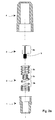
- Figure 2a is an exploded view, and parts 1, 2 and 4 show the antenna structure in longitudinal section, where 1 is a connector, 2 is a helical element, 3 is an insulating plate provided with a conductive pattern and 4 is a protective sheath made from an insulation material.
- the structure is assembled by attaching helical element 2 to connector 1 in a known manner, by pushing insulating plate 3 inside the helical element and pressing protective sheath 4 onto the whole structure, thus forming an antenna according to Figure 2b.
- the connector 1 is made from metal or another electrically conductive material, and on the outside of the sleeve-like lower part there is a screw thread for effective attachment of the antenna to the radio set (not shown in the Figure).
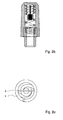
- Figure 2c shows the combined helical element and insulating plate viewed from above and from this it can be seen how the insulating plate 3 is positioned inside the helical element 2.
- a conductive pattern 5 On the surface of insulating plate 3 there is a conductive pattern 5, which on the lower part of the plate extends to the edges of the plate and on the upper part of the plate forms a straight conductor, so that it is possible to call it a whip element 5a.
- the lower part of the conductive pattern contacts at its edges the more tightly wound portion in the middle of the helix, which is marked with reference number 2c.
- the edges of the conductive pattern may be soldered fast to the helical wire at point 2c.
- the conductive pattern does not need to extend to the edges of insulating plate 3.
- the lower part of the whip element is connected to the junction of the helical element capacitively. Below the junction there is a portion of the helix marked with reference number 2a, and above the junction there is the portion of helix marked with reference number 2b.
- the turns of the helix connected to the connector 1 are not included in portion 2a, since the electrically conductive connector short-circuits these turns and they do not act as a radiating part of the antenna.
- the upper part of the insulating plate 3 may be wider than lower part thereof, as in the Figure, in which case its edges support the upper part 2b of the helix, or it may be of equal width, or of some other shape.
- Typical design parameters for an antenna of this sort are the number of turns in the lower part 2a and the upper part 2b of the helix and the position of the junction 2c to which the conductive pattern 5 of specific length is connected.
- the dimensioning of the helix determines the lower operating frequency of the antenna.
- Helix 2 is so designed that it is, charged by whip element 5a, in tune with the lower operating frequency of the antenna, for example the GSM or AMPS frequencies.
- whip element 5a in proportion to junction 2c determines the upper operating frequency of the antenna, which is determined by the proportion of the helix which is in its lower part 2a and by the length of the whip element 5a.
- the radiating antenna element is a connection in series of the lower part 2a of the helix and the whip element.
- the bandwidth of the operating frequencies is determined by the position of junction 2c or by the dimensional ratio of lower part 2a and upper part 2b of the helix. If the junction 2c is shifted downwards in the helix or the number of turns in the lower part 2a of the helix is reduced, the bandwidth of the higher operating frequency increases and the bandwidth of the lower operating frequency correspondingly decreases. If the junction 2c is shifted upwards or the number of turns in the lower part 2a of the helix increases in relation to the upper part 2b of the helix, the bandwidth of the higher operating frequency decreases and the bandwidth of the lower operating frequency increases.
- the operating frequencies and bandwidths of the antenna may be adjusted for desired system pairs.
- the selection of dimensions by trial and error is in itself a technique known to those skilled in the art.
- the whip element 5a is coated with an insulating material, friction attachment or adhesion will be involved. In that case, electrical connection between the helix and the whip element is capacitive.
- the insulation coating may of course also be removed from below the whip element before attachment, in which case the connection will be galvanic.
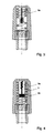
- Figure 4 shows an embodiment of the invention in which the whip element 5a formed on insulating plate 3 is not straight but forms a zig-zag pattern at the top.
Landscapes
- Engineering & Computer Science (AREA)
- Computer Networks & Wireless Communication (AREA)
- Support Of Aerials (AREA)
- Details Of Aerials (AREA)
- Variable-Direction Aerials And Aerial Arrays (AREA)
Applications Claiming Priority (2)
| Application Number | Priority Date | Filing Date | Title |
|---|---|---|---|
| FI963275A FI102434B (fi) | 1996-08-22 | 1996-08-22 | Kahden taajuuden antenni |
| FI963275 | 1996-08-22 |
Publications (2)
| Publication Number | Publication Date |
|---|---|
| EP0825672A2 true EP0825672A2 (de) | 1998-02-25 |
| EP0825672A3 EP0825672A3 (de) | 2000-03-22 |
Family
ID=8546517
Family Applications (1)
| Application Number | Title | Priority Date | Filing Date |
|---|---|---|---|
| EP97306410A Withdrawn EP0825672A3 (de) | 1996-08-22 | 1997-08-21 | Antenne für zwei Frequenzen |
Country Status (5)
| Country | Link |
|---|---|
| US (1) | US6016130A (de) |
| EP (1) | EP0825672A3 (de) |
| JP (1) | JPH10173430A (de) |
| AU (1) | AU731335B2 (de) |
| FI (1) | FI102434B (de) |
Cited By (17)
| Publication number | Priority date | Publication date | Assignee | Title |
|---|---|---|---|---|
| GB2335312A (en) * | 1998-02-27 | 1999-09-15 | Motorola Inc | An antenna adapted to operate in a plurality of frequency bands |
| GB2344938A (en) * | 1998-12-18 | 2000-06-21 | Nokia Mobile Phones Ltd | A multiple band, multiple co-axial element antenna |
| US6219007B1 (en) | 1999-08-23 | 2001-04-17 | The Whitaker Corporation | Antenna assembly |
| US6232930B1 (en) | 1997-12-18 | 2001-05-15 | The Whitaker Corporation | Dual band antenna and method of making same |
| WO2001035488A1 (en) * | 1999-11-10 | 2001-05-17 | Avantego Ab | Antenna arrangement |
| RU2174271C2 (ru) * | 1996-04-30 | 2001-09-27 | Квэлкомм Инкорпорейтед | Двухдиапазонная антенна |
| RU2205477C1 (ru) * | 2002-07-10 | 2003-05-27 | Лопатин Игорь Евгеньевич | Антенна |
| US6611691B1 (en) | 1998-12-24 | 2003-08-26 | Motorola, Inc. | Antenna adapted to operate in a plurality of frequency bands |
| GB2389232A (en) * | 2002-06-01 | 2003-12-03 | Motorola Inc | Multi-frequency band antenna using a dual-pitch coil |
| GB2418781A (en) * | 2004-07-02 | 2006-04-05 | Motorola Inc | Antenna with dual coaxial helical portions |
| EP1698020A1 (de) * | 2003-12-13 | 2006-09-06 | Motorola, Inc. | Antenne |
| US7113094B2 (en) | 1998-08-14 | 2006-09-26 | 3M Innovative Properties Company | Applications for radio frequency identification systems |
| US7554490B2 (en) | 2000-01-19 | 2009-06-30 | Fractus, S.A. | Space-filling miniature antennas |
| US7588185B2 (en) | 2001-06-07 | 2009-09-15 | 3M Innovative Properties Company | RFID data collection and use |
| US7619529B2 (en) | 1998-08-14 | 2009-11-17 | 3M Innovative Properties Company | Application for a radio frequency identification system |
| EP1263081B1 (de) * | 2001-05-31 | 2009-11-18 | Nec Corporation | Wendelantenne |
| US9899727B2 (en) | 2006-07-18 | 2018-02-20 | Fractus, S.A. | Multiple-body-configuration multimedia and smartphone multifunction wireless devices |
Families Citing this family (65)
| Publication number | Priority date | Publication date | Assignee | Title |
|---|---|---|---|---|
| JP2000223928A (ja) * | 1999-01-28 | 2000-08-11 | Smk Corp | アンテナ装置 |
| US6112102A (en) * | 1996-10-04 | 2000-08-29 | Telefonaktiebolaget Lm Ericsson | Multi-band non-uniform helical antennas |
| US6310578B1 (en) | 1997-10-28 | 2001-10-30 | Telefonaktiebolaget Lm Ericsson (Publ) | Multiple band telescope type antenna for mobile phone |
| US6329962B2 (en) | 1998-08-04 | 2001-12-11 | Telefonaktiebolaget Lm Ericsson (Publ) | Multiple band, multiple branch antenna for mobile phone |
| KR100306274B1 (ko) * | 1998-02-20 | 2001-09-26 | 윤종용 | 무선 송수신기를 위한 이중 대역 안테나 |
| US6154137A (en) | 1998-06-08 | 2000-11-28 | 3M Innovative Properties Company | Identification tag with enhanced security |
| US6166694A (en) * | 1998-07-09 | 2000-12-26 | Telefonaktiebolaget Lm Ericsson (Publ) | Printed twin spiral dual band antenna |
| US6353443B1 (en) | 1998-07-09 | 2002-03-05 | Telefonaktiebolaget Lm Ericsson (Publ) | Miniature printed spiral antenna for mobile terminals |
| US6424262B2 (en) | 1998-08-14 | 2002-07-23 | 3M Innovative Properties Company | Applications for radio frequency identification systems |
| CN100492388C (zh) | 1998-08-14 | 2009-05-27 | 3M创新有限公司 | 射频识别系统应用 |
| US6297784B1 (en) * | 1998-11-02 | 2001-10-02 | Auden Techno Corp. | Bi-frequency cellular telephone antenna |
| US6343208B1 (en) | 1998-12-16 | 2002-01-29 | Telefonaktiebolaget Lm Ericsson (Publ) | Printed multi-band patch antenna |
| US6172655B1 (en) * | 1999-02-12 | 2001-01-09 | Lockheed Martin Corporation | Ultra-short helical antenna and array thereof |
| US6262693B1 (en) * | 1999-05-03 | 2001-07-17 | T&M Antennas | Snap fit compression antenna assembly |
| US6781549B1 (en) | 1999-10-12 | 2004-08-24 | Galtronics Ltd. | Portable antenna |
| DE10037472C2 (de) * | 2000-08-01 | 2002-09-26 | Siemens Ag | Verfahren zum Einbau einer Antenne |
| JP2002176310A (ja) * | 2000-12-06 | 2002-06-21 | Nippon Antenna Co Ltd | 2共振アンテナ |
| KR100406352B1 (ko) * | 2001-03-29 | 2003-11-28 | 삼성전기주식회사 | 안테나 및 그 제조방법 |
| WO2003034603A1 (en) * | 2001-10-13 | 2003-04-24 | Samsung Electronics Co., Ltd | Mobile communication system having multi-band antenna |
| WO2003105276A1 (en) * | 2002-06-06 | 2003-12-18 | Galtronics Ltd. | Multi-band improvements to a monopole helical_antenna |
| JP4037703B2 (ja) * | 2002-06-28 | 2008-01-23 | 日本電気株式会社 | 内蔵アンテナ及び無線機 |
| US7417588B2 (en) * | 2004-01-30 | 2008-08-26 | Fractus, S.A. | Multi-band monopole antennas for mobile network communications devices |
| CN1989652B (zh) * | 2004-06-28 | 2013-03-13 | 脉冲芬兰有限公司 | 天线部件 |
| US7202836B2 (en) * | 2005-05-06 | 2007-04-10 | Motorola, Inc. | Antenna apparatus and method of forming same |
| KR20060129773A (ko) * | 2005-06-13 | 2006-12-18 | 삼성전자주식회사 | 휴대용 단말기의 안테나 장치 |
| FI20055420A0 (fi) * | 2005-07-25 | 2005-07-25 | Lk Products Oy | Säädettävä monikaista antenni |
| FI119009B (fi) * | 2005-10-03 | 2008-06-13 | Pulse Finland Oy | Monikaistainen antennijärjestelmä |
| FI118872B (fi) | 2005-10-10 | 2008-04-15 | Pulse Finland Oy | Sisäinen antenni |
| FI118782B (fi) | 2005-10-14 | 2008-03-14 | Pulse Finland Oy | Säädettävä antenni |
| FI119577B (fi) * | 2005-11-24 | 2008-12-31 | Pulse Finland Oy | Monikaistainen antennikomponentti |
| US8618990B2 (en) | 2011-04-13 | 2013-12-31 | Pulse Finland Oy | Wideband antenna and methods |
| US10211538B2 (en) | 2006-12-28 | 2019-02-19 | Pulse Finland Oy | Directional antenna apparatus and methods |
| FI20075269A0 (fi) * | 2007-04-19 | 2007-04-19 | Pulse Finland Oy | Menetelmä ja järjestely antennin sovittamiseksi |
| FI120427B (fi) | 2007-08-30 | 2009-10-15 | Pulse Finland Oy | Säädettävä monikaista-antenni |
| CN101316005B (zh) * | 2008-07-10 | 2012-02-15 | 华南理工大学 | 双频段叠层介质加载螺旋天线 |
| FI20096134A0 (fi) | 2009-11-03 | 2009-11-03 | Pulse Finland Oy | Säädettävä antenni |
| FI20096251A0 (sv) | 2009-11-27 | 2009-11-27 | Pulse Finland Oy | MIMO-antenn |
| US8847833B2 (en) * | 2009-12-29 | 2014-09-30 | Pulse Finland Oy | Loop resonator apparatus and methods for enhanced field control |
| FI20105158A7 (fi) | 2010-02-18 | 2011-08-19 | Pulse Finland Oy | Kuorisäteilijällä varustettu antenni |
| JP5293645B2 (ja) * | 2010-03-03 | 2013-09-18 | 株式会社日本自動車部品総合研究所 | アンテナ装置 |
| US9406998B2 (en) | 2010-04-21 | 2016-08-02 | Pulse Finland Oy | Distributed multiband antenna and methods |
| JP5235941B2 (ja) * | 2010-05-21 | 2013-07-10 | 原田工業株式会社 | 車両用アンテナ |
| FI20115072A0 (fi) | 2011-01-25 | 2011-01-25 | Pulse Finland Oy | Moniresonanssiantenni, -antennimoduuli ja radiolaite |
| US9673507B2 (en) | 2011-02-11 | 2017-06-06 | Pulse Finland Oy | Chassis-excited antenna apparatus and methods |
| US8648752B2 (en) | 2011-02-11 | 2014-02-11 | Pulse Finland Oy | Chassis-excited antenna apparatus and methods |
| US8866689B2 (en) | 2011-07-07 | 2014-10-21 | Pulse Finland Oy | Multi-band antenna and methods for long term evolution wireless system |
| US9450291B2 (en) | 2011-07-25 | 2016-09-20 | Pulse Finland Oy | Multiband slot loop antenna apparatus and methods |
| US9123990B2 (en) | 2011-10-07 | 2015-09-01 | Pulse Finland Oy | Multi-feed antenna apparatus and methods |
| US9531058B2 (en) | 2011-12-20 | 2016-12-27 | Pulse Finland Oy | Loosely-coupled radio antenna apparatus and methods |
| US9484619B2 (en) | 2011-12-21 | 2016-11-01 | Pulse Finland Oy | Switchable diversity antenna apparatus and methods |
| US8988296B2 (en) | 2012-04-04 | 2015-03-24 | Pulse Finland Oy | Compact polarized antenna and methods |
| US9979078B2 (en) | 2012-10-25 | 2018-05-22 | Pulse Finland Oy | Modular cell antenna apparatus and methods |
| US10069209B2 (en) | 2012-11-06 | 2018-09-04 | Pulse Finland Oy | Capacitively coupled antenna apparatus and methods |
| US9647338B2 (en) | 2013-03-11 | 2017-05-09 | Pulse Finland Oy | Coupled antenna structure and methods |
| US10079428B2 (en) | 2013-03-11 | 2018-09-18 | Pulse Finland Oy | Coupled antenna structure and methods |
| US9634383B2 (en) | 2013-06-26 | 2017-04-25 | Pulse Finland Oy | Galvanically separated non-interacting antenna sector apparatus and methods |
| US9680212B2 (en) | 2013-11-20 | 2017-06-13 | Pulse Finland Oy | Capacitive grounding methods and apparatus for mobile devices |
| US9590308B2 (en) | 2013-12-03 | 2017-03-07 | Pulse Electronics, Inc. | Reduced surface area antenna apparatus and mobile communications devices incorporating the same |
| US9350081B2 (en) | 2014-01-14 | 2016-05-24 | Pulse Finland Oy | Switchable multi-radiator high band antenna apparatus |
| US9948002B2 (en) | 2014-08-26 | 2018-04-17 | Pulse Finland Oy | Antenna apparatus with an integrated proximity sensor and methods |
| US9973228B2 (en) | 2014-08-26 | 2018-05-15 | Pulse Finland Oy | Antenna apparatus with an integrated proximity sensor and methods |
| US9722308B2 (en) | 2014-08-28 | 2017-08-01 | Pulse Finland Oy | Low passive intermodulation distributed antenna system for multiple-input multiple-output systems and methods of use |
| US9906260B2 (en) | 2015-07-30 | 2018-02-27 | Pulse Finland Oy | Sensor-based closed loop antenna swapping apparatus and methods |
| US11637378B2 (en) * | 2018-11-02 | 2023-04-25 | Intuitive Surgical Operations, Inc. | Coiled dipole antenna |
| TWI674706B (zh) * | 2018-12-20 | 2019-10-11 | 和碩聯合科技股份有限公司 | 雙頻圓極化天線結構 |
Family Cites Families (11)
| Publication number | Priority date | Publication date | Assignee | Title |
|---|---|---|---|---|
| AU2284370A (en) * | 1970-11-30 | 1972-06-01 | Normal-mode helix aerials | |
| US4137534A (en) * | 1977-05-26 | 1979-01-30 | Goodnight Roy G | Vertical antenna with low angle of radiation |
| US4442438A (en) * | 1982-03-29 | 1984-04-10 | Motorola, Inc. | Helical antenna structure capable of resonating at two different frequencies |
| JPS6098705A (ja) * | 1983-11-04 | 1985-06-01 | Gijutsu Kenkyu Kumiai Iryo Fukushi Kiki Kenkyusho | ヘリカル空中線 |
| GB2206243A (en) * | 1987-06-24 | 1988-12-29 | Panorama Antennas Ltd | Dual-frequency helical antenna |
| DE69215283T2 (de) * | 1991-07-08 | 1997-03-20 | Nippon Telegraph & Telephone | Ausfahrbares Antennensystem |
| JP3300818B2 (ja) * | 1992-10-27 | 2002-07-08 | 三省電機株式会社 | アンテナの支持・接続方法、および同支持・接続構造 |
| KR100232981B1 (ko) * | 1995-02-07 | 1999-12-01 | 이데이 노부유끼 | 2주파수 대역용 안테나 장치 |
| FI98165C (fi) * | 1995-06-05 | 1997-04-25 | Lk Products Oy | Kaksitoiminen antenni |
| US5900839A (en) * | 1996-09-25 | 1999-05-04 | U.S. Philips Corporation | Radio transmission apparatus comprising a retractable antenna and an antenna device for such apparatus |
| DE19715726C2 (de) * | 1997-04-15 | 2001-08-30 | Siemens Ag | Antennenvorrichtung für Mobilfunkgeräte |
-
1996
- 1996-08-22 FI FI963275A patent/FI102434B/fi active
-
1997
- 1997-08-21 US US08/915,953 patent/US6016130A/en not_active Expired - Fee Related
- 1997-08-21 EP EP97306410A patent/EP0825672A3/de not_active Withdrawn
- 1997-08-22 AU AU35202/97A patent/AU731335B2/en not_active Ceased
- 1997-08-22 JP JP9226839A patent/JPH10173430A/ja active Pending
Cited By (36)
| Publication number | Priority date | Publication date | Assignee | Title |
|---|---|---|---|---|
| RU2174271C2 (ru) * | 1996-04-30 | 2001-09-27 | Квэлкомм Инкорпорейтед | Двухдиапазонная антенна |
| US6232930B1 (en) | 1997-12-18 | 2001-05-15 | The Whitaker Corporation | Dual band antenna and method of making same |
| GB2335312A (en) * | 1998-02-27 | 1999-09-15 | Motorola Inc | An antenna adapted to operate in a plurality of frequency bands |
| GB2335312B (en) * | 1998-02-27 | 2002-10-09 | Motorola Inc | An antenna adapted to operate in a plurality of frequency bands |
| US7728732B2 (en) | 1998-08-14 | 2010-06-01 | 3M Innovative Properties Company | Applications for radio frequency identification systems |
| US7113094B2 (en) | 1998-08-14 | 2006-09-26 | 3M Innovative Properties Company | Applications for radio frequency identification systems |
| US7471205B2 (en) | 1998-08-14 | 2008-12-30 | 3M Innovative Properties Company | Applications for radio frequency identification systems |
| US7123151B2 (en) | 1998-08-14 | 2006-10-17 | 3M Innovative Properties Company | Applications for radio frequency identification systems |
| US8502673B2 (en) | 1998-08-14 | 2013-08-06 | 3M Innovative Properties Company | Applications for radio frequency identification systems |
| US7619529B2 (en) | 1998-08-14 | 2009-11-17 | 3M Innovative Properties Company | Application for a radio frequency identification system |
| US6300913B1 (en) | 1998-12-18 | 2001-10-09 | Nokia Mobile Phones Ltd. | Antenna |
| GB2344938A (en) * | 1998-12-18 | 2000-06-21 | Nokia Mobile Phones Ltd | A multiple band, multiple co-axial element antenna |
| US6611691B1 (en) | 1998-12-24 | 2003-08-26 | Motorola, Inc. | Antenna adapted to operate in a plurality of frequency bands |
| US6219007B1 (en) | 1999-08-23 | 2001-04-17 | The Whitaker Corporation | Antenna assembly |
| WO2001035488A1 (en) * | 1999-11-10 | 2001-05-17 | Avantego Ab | Antenna arrangement |
| US7554490B2 (en) | 2000-01-19 | 2009-06-30 | Fractus, S.A. | Space-filling miniature antennas |
| US8558741B2 (en) | 2000-01-19 | 2013-10-15 | Fractus, S.A. | Space-filling miniature antennas |
| US10355346B2 (en) | 2000-01-19 | 2019-07-16 | Fractus, S.A. | Space-filling miniature antennas |
| US8610627B2 (en) | 2000-01-19 | 2013-12-17 | Fractus, S.A. | Space-filling miniature antennas |
| US8207893B2 (en) | 2000-01-19 | 2012-06-26 | Fractus, S.A. | Space-filling miniature antennas |
| US8212726B2 (en) | 2000-01-19 | 2012-07-03 | Fractus, Sa | Space-filling miniature antennas |
| US8471772B2 (en) | 2000-01-19 | 2013-06-25 | Fractus, S.A. | Space-filling miniature antennas |
| EP1263081B1 (de) * | 2001-05-31 | 2009-11-18 | Nec Corporation | Wendelantenne |
| US7588185B2 (en) | 2001-06-07 | 2009-09-15 | 3M Innovative Properties Company | RFID data collection and use |
| GB2389232B (en) * | 2002-06-01 | 2004-10-27 | Motorola Inc | Multi-frequency band antenna and methods of tuning and manufacture |
| GB2389232A (en) * | 2002-06-01 | 2003-12-03 | Motorola Inc | Multi-frequency band antenna using a dual-pitch coil |
| RU2205477C1 (ru) * | 2002-07-10 | 2003-05-27 | Лопатин Игорь Евгеньевич | Антенна |
| EP1698020A1 (de) * | 2003-12-13 | 2006-09-06 | Motorola, Inc. | Antenne |
| GB2418781B (en) * | 2004-07-02 | 2006-11-22 | Motorola Inc | Antenna with dual helical portions for use in radio communications |
| GB2418781A (en) * | 2004-07-02 | 2006-04-05 | Motorola Inc | Antenna with dual coaxial helical portions |
| US9899727B2 (en) | 2006-07-18 | 2018-02-20 | Fractus, S.A. | Multiple-body-configuration multimedia and smartphone multifunction wireless devices |
| US10644380B2 (en) | 2006-07-18 | 2020-05-05 | Fractus, S.A. | Multiple-body-configuration multimedia and smartphone multifunction wireless devices |
| US11031677B2 (en) | 2006-07-18 | 2021-06-08 | Fractus, S.A. | Multiple-body-configuration multimedia and smartphone multifunction wireless devices |
| US11349200B2 (en) | 2006-07-18 | 2022-05-31 | Fractus, S.A. | Multiple-body-configuration multimedia and smartphone multifunction wireless devices |
| US11735810B2 (en) | 2006-07-18 | 2023-08-22 | Fractus, S.A. | Multiple-body-configuration multimedia and smartphone multifunction wireless devices |
| US12095149B2 (en) | 2006-07-18 | 2024-09-17 | Fractus, S.A. | Multiple-body-configuration multimedia and smartphone multifunction wireless devices |
Also Published As
| Publication number | Publication date |
|---|---|
| JPH10173430A (ja) | 1998-06-26 |
| AU3520297A (en) | 1998-02-26 |
| FI102434B1 (fi) | 1998-11-30 |
| FI963275A0 (fi) | 1996-08-22 |
| FI102434B (fi) | 1998-11-30 |
| EP0825672A3 (de) | 2000-03-22 |
| US6016130A (en) | 2000-01-18 |
| FI963275L (fi) | 1998-02-23 |
| AU731335B2 (en) | 2001-03-29 |
Similar Documents
| Publication | Publication Date | Title |
|---|---|---|
| US6016130A (en) | Dual-frequency antenna | |
| FI98165C (fi) | Kaksitoiminen antenni | |
| US6661391B2 (en) | Antenna and radio device comprising the same | |
| EP0960449B1 (de) | Helixantenne für zwei frequenzen | |
| US6054966A (en) | Antenna operating in two frequency ranges | |
| EP0855759B1 (de) | Einfache Antenne für zwei Frequenzen | |
| KR100384656B1 (ko) | 기생 소자를 구비한 이중-대역 나선형 안테나 | |
| KR100356196B1 (ko) | 2주파 대응 안테나 장치 및 이를 사용한 이동 통신기기 | |
| WO1998005090A1 (en) | Bent-segment helical antenna | |
| WO1998005090A9 (en) | Bent-segment helical antenna | |
| WO1997018601A1 (en) | Dual band antenna means | |
| US6628241B1 (en) | Antenna device and communication terminal comprising the same | |
| US6525692B2 (en) | Dual-band antenna for mobile telecommunication units | |
| US20090315786A1 (en) | Antenna with increased electrical length and wireless communication device including the same | |
| EP0987788A2 (de) | Mehrband-Antenne | |
| AU751800B2 (en) | Antenna assembly and a mobile radio apparatus using the same | |
| EP1267439B1 (de) | Mehrbandantenne mit zwei konzentrischen verschachtelten Antennen, wobei die äussere eine meanderförmige Antenne ist | |
| US6300913B1 (en) | Antenna | |
| JP2003087031A (ja) | アンテナ | |
| EP0978155A1 (de) | Mehrband-stabantenne | |
| HK1033207B (en) | Dual-band helix antenna with parasitic element | |
| HK1052810A1 (en) | Helical antenna |
Legal Events
| Date | Code | Title | Description |
|---|---|---|---|
| PUAI | Public reference made under article 153(3) epc to a published international application that has entered the european phase |
Free format text: ORIGINAL CODE: 0009012 |
|
| AK | Designated contracting states |
Kind code of ref document: A2 Designated state(s): DE DK FR GB SE |
|
| PUAL | Search report despatched |
Free format text: ORIGINAL CODE: 0009013 |
|
| AK | Designated contracting states |
Kind code of ref document: A3 Designated state(s): AT BE CH DE DK ES FI FR GB GR IE IT LI LU MC NL PT SE |
|
| RAP1 | Party data changed (applicant data changed or rights of an application transferred) |
Owner name: FILTRONIC LK OY |
|
| 17P | Request for examination filed |
Effective date: 20000829 |
|
| AKX | Designation fees paid |
Free format text: DE DK FR GB SE |
|
| STAA | Information on the status of an ep patent application or granted ep patent |
Free format text: STATUS: THE APPLICATION HAS BEEN WITHDRAWN |
|
| 18W | Application withdrawn |
Withdrawal date: 20021021 |