EP0826357A1 - Halter für eine Trag- und/oder Hebevorrichtung, insbesondere eine Hebevorrichtung für Patienten - Google Patents
Halter für eine Trag- und/oder Hebevorrichtung, insbesondere eine Hebevorrichtung für Patienten Download PDFInfo
- Publication number
- EP0826357A1 EP0826357A1 EP97112825A EP97112825A EP0826357A1 EP 0826357 A1 EP0826357 A1 EP 0826357A1 EP 97112825 A EP97112825 A EP 97112825A EP 97112825 A EP97112825 A EP 97112825A EP 0826357 A1 EP0826357 A1 EP 0826357A1
- Authority
- EP
- European Patent Office
- Prior art keywords
- holder according
- side walls
- wall part
- holder
- lifting device
- Prior art date
- Legal status (The legal status is an assumption and is not a legal conclusion. Google has not performed a legal analysis and makes no representation as to the accuracy of the status listed.)
- Granted
Links
Images


Classifications
-
- A—HUMAN NECESSITIES
- A61—MEDICAL OR VETERINARY SCIENCE; HYGIENE
- A61G—TRANSPORT, PERSONAL CONVEYANCES OR ACCOMMODATION SPECIALLY ADAPTED FOR PATIENTS OR DISABLED PERSONS; OPERATING TABLES OR CHAIRS; CHAIRS FOR DENTISTRY; FUNERAL DEVICES
- A61G7/00—Beds specially adapted for nursing; Devices for lifting patients or disabled persons
- A61G7/10—Devices for lifting patients or disabled persons, e.g. special adaptations of hoists thereto
- A61G7/1038—Manual lifting aids, e.g. frames or racks
-
- A—HUMAN NECESSITIES
- A61—MEDICAL OR VETERINARY SCIENCE; HYGIENE
- A61G—TRANSPORT, PERSONAL CONVEYANCES OR ACCOMMODATION SPECIALLY ADAPTED FOR PATIENTS OR DISABLED PERSONS; OPERATING TABLES OR CHAIRS; CHAIRS FOR DENTISTRY; FUNERAL DEVICES
- A61G7/00—Beds specially adapted for nursing; Devices for lifting patients or disabled persons
- A61G7/05—Parts, details or accessories of beds
- A61G7/053—Aids for getting into, or out of, bed, e.g. steps, chairs, cane-like supports
- A61G7/0533—Lifting poles
-
- A—HUMAN NECESSITIES
- A61—MEDICAL OR VETERINARY SCIENCE; HYGIENE
- A61G—TRANSPORT, PERSONAL CONVEYANCES OR ACCOMMODATION SPECIALLY ADAPTED FOR PATIENTS OR DISABLED PERSONS; OPERATING TABLES OR CHAIRS; CHAIRS FOR DENTISTRY; FUNERAL DEVICES
- A61G7/00—Beds specially adapted for nursing; Devices for lifting patients or disabled persons
- A61G7/10—Devices for lifting patients or disabled persons, e.g. special adaptations of hoists thereto
-
- A—HUMAN NECESSITIES
- A61—MEDICAL OR VETERINARY SCIENCE; HYGIENE
- A61G—TRANSPORT, PERSONAL CONVEYANCES OR ACCOMMODATION SPECIALLY ADAPTED FOR PATIENTS OR DISABLED PERSONS; OPERATING TABLES OR CHAIRS; CHAIRS FOR DENTISTRY; FUNERAL DEVICES
- A61G7/00—Beds specially adapted for nursing; Devices for lifting patients or disabled persons
- A61G7/10—Devices for lifting patients or disabled persons, e.g. special adaptations of hoists thereto
- A61G7/104—Devices carried or supported by
- A61G7/1044—Stationary fixed means, e.g. fixed to a surface or bed
Definitions
- the invention relates to a holder for a support and / or Lifting device, in particular a lifting device for patients, according to the preamble of claim 1.
- lifting or patient lifts It is known to carry or lift devices for patients, so-called lifting or patient lifts, with two with Spacers arranged one above the other on a wall of the respective installation room. They have a push-through opening for a support tube of the lifting device. With these holders, the lifting device often not on every wall, especially not on Lightweight walls to be attached. The on the lifting device acting, relatively high forces can from a Lightweight wall can not be reliably included. In such a case, the lifting device could be attached one between a floor and the ceiling clamped support are provided. However, it is not suitable for suspended ceilings. Besides, could when swiveling with the lifting device affect.
- the invention has for its object a holder to train the generic type so that it at as little space as possible when using the Carrying and / or lifting device occurring high forces pick up properly and hit the floor and / or Wall can transfer.
- the holder designed as a stand that is secure on the floor Has so that it is both free in the room, but also if necessary and for space reasons attached to a wall can be where he projects only insignificantly over these.
- the lifting device is simple and safe secured to the stand. While using the lifting device the forces that occur are perfectly correct transfer the stand feet to the floor so that even when the stand is attached to a lightweight wall do not apply excessive forces to them.
- the invention Stand can be used and attached anywhere without any special features, as if it were a lightweight construction, respect must become.
- the lifting device can be installed on the stand easily in the desired positions be pivoted so that undisturbed work is guaranteed is. Finally, the stand also takes a relative takes up little space.
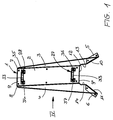
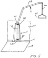
- the holder 1 according to FIGS. 1 to 5 is preferably used for attaching a lifting device H for patients, a so-called patient lift (Fig. 5).
- the holder 1 is designed as a stand that is free-standing on a Floor B can be attached.
- the stand 1 can also be attached to a wall W standing. But it is also possible, the holder H on the floor B and on the wall W to attach, thereby providing optimal support for the holder H is reached.
- the holder 1 has a rectangular rear wall 2 as well these laterally projecting side walls 3 and 4, which the Stand feet 5, 6 have. For this, the bottom ends the side walls 3, 4 bent at right angles to the outside.
- the holder 1 is mirror-symmetrical to its vertical center plane educated.
- the side walls 3, 4 have approximately triangular outline; they are preferably in one piece formed with the rear wall 2.
- the top margins 7, 8 of the sidewalls 3, 4 tapering to the top lie at the same height as the upper edge 9 of the rear wall 2.
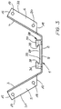
- the width of the lower edges 10, 11 of the side walls 3, 4 is larger than the width of the rear wall 2 (Fig. 1, 3).
- the feet 5, 6 have an approximately trapezoidal outline, such that the free longitudinal edges of the feet 5, 6 are shorter than those adjoining the side walls 3, 4 Edges.
- the rear wall 2 and the side walls 3, 4 each have a recess provided on its lower edge 9 ', 10, 11 12 to 14.
- the recess 12 in the rear wall 2 extends across their entire width, while the recesses 13, 14 have only a small width and differ from the rear wall 2 only over a small part of the width of the side walls 3, 4 extend.
- the cutouts 12 have the same height and delimit a stand opening 12 to 14. Is the holder 1 with its rear wall 2 on the Wall W, then through the recesses 12 to 14 for example, a bottom bar attached to the lower end of the wall L (Fig. 5) extend so that the holder 1 in spite of the skirting board L projecting over the wall W. rest perfectly against the wall W with its rear wall 2 can and has a high level of stability.
- the side walls 3, 4 are under one obtuse angle to the rear wall 2, from which the side walls 3, 4 diverging from each other under each run at the same angle.
- the recesses 13, 14 have the feet 5, 6 distance from the rear wall 2 (Fig. 3).
- the free edges 15 facing away from the rear wall 2, 16 of the feet 5, 6 are perpendicular to the side walls 3, 4, while the opposite edges 17, 18 are acute-angled run to the side walls 3 and 4.
- With relative close to the edges 15, 17 and 16, 18 have the feet 5, 6 through openings 17, 18 and 19, 20 for securing parts such as screws and the like, with which the feet 5, 6 are flat holder 1 resting on the floor B on the floor B can be attached.
- the holder 1 can be both free in the room as well as with its rear wall 2 on the wall W to be fitted over the entire surface. In this case the holder 1 is advantageous over other fasteners also attached to the wall. They are through openings 21 to 26 inserted or screwed into the rear wall 2. As shown in FIG. 2, low Distance from the upper and lower edges 9 and 12 respectively Rear wall 2 each provided at the same height Openings 21, 22 and 23, 24 are provided. Halfway up the wall 2 are two additional openings 25 and 26 available. At a distance above openings 23 and 24 and points at a distance below the openings 21 and 22 the rear wall 2 in the area between the side walls 3, 4 Connection parts 27 and 28, which, like FIGS. 2 and 3 each show a dovetail-shaped opening 29, 30 have.
- openings are used to receive a corresponding counterpart (not shown) 41, 42 (Fig. 5) of the lifting device to be secured on the holder 1 H.
- the connecting parts 27 and 28 are relatively small Distance from openings 21, 22 and 23, 24, however at a relatively large distance from the central openings 25, 26. This means that the lift H is relatively wide apart fastening points created, so that he has a secure hold on stand 1.
- the connectors 27, 28 are advantageous on the rear wall 2 releasably attached and lie with a foot piece 32, 33 on the rear wall 2. From the foot pieces 32, 33 stand end pieces 34, 35; 36, 37 before, facing each other Edges 38, 39 converging from the foot piece 32, 33 run and the side faces of the dovetail-shaped Limit openings 29, 30.
- the holder 1 has due to its opposite the rear wall 2 outwardly extending side walls 3, 4 and the feet 5, 6 a high level of stability. He is as a result of this Training on relatively far apart Places supported on floor B. An additional facility and attachment to the wall W ensures one even more secure hold of the lifting device H. With the help the holder 1, the lifting device H can easily can also be attached to a lightweight wall. In this Case transfers the holder when the lifting device is loaded H occurring forces on the side walls 3, 4th and their feet 5, 6 perfectly on the floor. Even if the holder 1 is mounted free-standing on the floor B, it can be the relative acting on the lifting device absorb high forces and hit the ground transfer.
- the lifting device arranged in the holder 1 H (FIG. 5) can easily be pivoted through 180 °, since the load on the side walls 3, 4 or feet 5, 6 supported perfectly over the entire swivel range becomes. The lifting device H is protected in the holder 1 housed, with the holder only relatively little space takes up.
- the lifting device H has a stand 40 (FIG. 5) which the counterparts 41, 42 are attached, which in assembled Location of the lifting device H in the dovetail-shaped Openings 29, 30 of the connecting parts 27, 28 intervene.
- the stand 40 stands on the floor B. and goes into a gallows arm at the top 43 over, on which a rope 44 or the like Handle 45 is attached.
- the rope 44 can also be in or along the support arm 43 and the stand 40 to a take-up drum be guided so that the rope 44 for adjustment of the handle 45 are wound up or unwound can.
- the stand 40 is in the counterparts 41, 42 rotatably arranged so that it rotated to the extent necessary can be.
Landscapes
- Health & Medical Sciences (AREA)
- Nursing (AREA)
- Life Sciences & Earth Sciences (AREA)
- Animal Behavior & Ethology (AREA)
- General Health & Medical Sciences (AREA)
- Public Health (AREA)
- Veterinary Medicine (AREA)
- Invalid Beds And Related Equipment (AREA)
- Load-Engaging Elements For Cranes (AREA)
- Forklifts And Lifting Vehicles (AREA)
Abstract
Description
- Fig. 1
- einen erfindungsgemäßen, als Ständer ausgebildeten Halter in perspektivischer Darstellung,
- Fig. 2
- den Ständer nach Fig. 1 in Vorderansicht,
- Fig. 3
- den Ständer nach Fig. 1 in Draufsicht und in vergrößerter Darstellung,
- Fig. 4
- den Ständer nach Fig. 1 in Seitenansicht gemäß Pfeil IV in Fig. 1,
- Fig. 5
- in vereinfachter Darstellung den erfindungsgemäßen Halter mit einem daran angeordneten Patientenhebelift.
Claims (12)
- Halter für eine Trag- und/oder Hebevorrichtung, insbesondere eine Hebevorrichtung für Patienten, mit mindestens einem an einer Wand oder dergleichen zu befestigenden Anschlußteil und einer Aufnahmeöffnung für die Tragvorrichtung,
dadurch gekennzeichnet, daß der Halter (1) als Ständer mit mindestens einem auf dem Boden (B) aufliegenden Fuß (5, 6) und mindestens einem Wandteil (2) ausgebildet ist. - Halter nach Anspruch 1,
dadurch gekennzeichnet, daß er zwei mit Abstand voneinander liegende, plattenartige Füße (5, 6) aufweist, mit denen der Halter (1) auf dem Boden (B) aufliegt. - Halter nach Anspruch 1 oder 2,
dadurch gekennzeichnet, daß die Füße (5, 6) an einer Seitenwand (3, 4) vorgesehen sind und vorzugsweise durch einen quer, vorteilhaft rechtwinklig, abgebogenen Rand der Seitenwände (3, 4) gebildet sind. - Halter nach Anspruch 3,
dadurch gekennzeichnet, daß mindestens die eine Seitenwand, vorzugsweise beide Seitenwände (3, 4), mit dem vorzugsweise rechteckigförmig ausgebildeten Wandteil (2) einen stumpfen Winkel einschließen. - Halter nach Anspruch 3 oder 4,
dadurch gekennzeichnet, daß die Seitenwände (3, 4) gleichen, etwa dreieckförmigen Umriß haben und sich vorzugsweise nach oben verjüngen. - Halter nach Anspruch 5,
dadurch gekennzeichnet, daß die Seitenwände (3, 4) obere Ränder (7, 8) haben, die mit einem oberen Rand (9) des Wandteiles (2) in einer gemeinsamen, vorzugsweise horizontalen Ebene liegen, und daß vorteilhafterweise die oberen Ränder (7, 8) der Seitenwände (3, 4) an den oberen Rand (9) des Wandteiles (2) anschließen. - Halter nach einem der Ansprüche 3 bis 6,
dadurch gekennzeichnet, daß die größte, im Bereich der unteren Ränder (10, 11) vorgesehene Breite der Seitenwände (3, 4) größer ist als die Breite des Wandteiles (2). - Halter nach einem der Ansprüche 1 bis 7,
dadurch gekennzeichnet, daß der Wandteil (2) und/oder die Seitenwände (3, 4) eine jeweils an ihrem unteren Rand (9', 10, 11) vorgesehene Aussparung (12 bis 14) aufweisen. - Halter nach Anspruch 8,
dadurch gekennzeichnet, daß sich die Aussparung (12) des Wandteiles (2) über dessen ganze Breite erstreckt. - Halter nach Anspruch 8 oder 9,
dadurch gekennzeichnet, daß die Aussparungen (13, 14) der Seitenwände (3, 4) schmaler sind als die Aussparung (12) des Wandteiles (2). - Halter nach einem der Ansprüche 1 bis 10,
dadurch gekennzeichnet, daß mindestens die Füße (5, 6), vorzugsweise die Füße und der Wandteil (2), Öffnungen (15 bis 18; 21 bis 26) für Befestigungsteile, wie Schrauben oder dergleichen, aufweisen. - Halter nach einem der Ansprüche 1 bis 11,
dadurch gekennzeichnet, daß der Wandteil (2) zwei mit Abstand übereinander liegende Anschlußteile (27, 28) für ein Kupplungsteil der Tragvorrichtung (H) aufweist, die vorzugsweise am Wandteil (2) lösbar befestigt, vorzugsweise verschraubt sind.
Applications Claiming Priority (2)
| Application Number | Priority Date | Filing Date | Title |
|---|---|---|---|
| DE29615004U | 1996-08-29 | ||
| DE29615004U DE29615004U1 (de) | 1996-08-29 | 1996-08-29 | Halter für eine Trag- und/oder Hebevorrichtung, insbesondere eine Hebevorrichtung für Patienten |
Publications (2)
| Publication Number | Publication Date |
|---|---|
| EP0826357A1 true EP0826357A1 (de) | 1998-03-04 |
| EP0826357B1 EP0826357B1 (de) | 2002-12-04 |
Family
ID=8028492
Family Applications (1)
| Application Number | Title | Priority Date | Filing Date |
|---|---|---|---|
| EP97112825A Expired - Lifetime EP0826357B1 (de) | 1996-08-29 | 1997-07-25 | Halter für eine Trag- und/oder Hebevorrichtung, insbesondere eine Hebevorrichtung für Patienten |
Country Status (3)
| Country | Link |
|---|---|
| EP (1) | EP0826357B1 (de) |
| AT (1) | ATE228812T1 (de) |
| DE (2) | DE29615004U1 (de) |
Citations (3)
| Publication number | Priority date | Publication date | Assignee | Title |
|---|---|---|---|---|
| BE811502A (nl) * | 1974-02-25 | 1974-06-17 | Orthopedische ziekenoprichter voor bevestiging aan de muur | |
| DE8613814U1 (de) * | 1986-05-22 | 1986-08-14 | Meinhardt, Werner, Dipl.-Ing., 2087 Hasloh | Haltegestell |
| DE29614203U1 (de) * | 1996-08-16 | 1996-10-24 | Cavelius, Stefan, 66798 Wallerfangen | Befestigungsstange für Gymnastikbänder |
-
1996
- 1996-08-29 DE DE29615004U patent/DE29615004U1/de not_active Expired - Lifetime
-
1997
- 1997-07-25 AT AT97112825T patent/ATE228812T1/de not_active IP Right Cessation
- 1997-07-25 EP EP97112825A patent/EP0826357B1/de not_active Expired - Lifetime
- 1997-07-25 DE DE59708868T patent/DE59708868D1/de not_active Expired - Fee Related
Patent Citations (3)
| Publication number | Priority date | Publication date | Assignee | Title |
|---|---|---|---|---|
| BE811502A (nl) * | 1974-02-25 | 1974-06-17 | Orthopedische ziekenoprichter voor bevestiging aan de muur | |
| DE8613814U1 (de) * | 1986-05-22 | 1986-08-14 | Meinhardt, Werner, Dipl.-Ing., 2087 Hasloh | Haltegestell |
| DE29614203U1 (de) * | 1996-08-16 | 1996-10-24 | Cavelius, Stefan, 66798 Wallerfangen | Befestigungsstange für Gymnastikbänder |
Also Published As
| Publication number | Publication date |
|---|---|
| ATE228812T1 (de) | 2002-12-15 |
| DE59708868D1 (de) | 2003-01-16 |
| EP0826357B1 (de) | 2002-12-04 |
| DE29615004U1 (de) | 1996-10-24 |
Similar Documents
| Publication | Publication Date | Title |
|---|---|---|
| EP0537151A1 (de) | Bausatz zur herstellung von büro-arbeitstischen. | |
| DE2828477A1 (de) | Konsole fuer einen fahrzeugsitz | |
| EP0826357B1 (de) | Halter für eine Trag- und/oder Hebevorrichtung, insbesondere eine Hebevorrichtung für Patienten | |
| EP4103015B1 (de) | Aufhängevorrichtung | |
| DE10210778B4 (de) | Gehäuse oder Gestell mit einer Kabelführungsvorrichtung | |
| DE3438418A1 (de) | Stuetzen- oder rahmenanordnung fuer regalsysteme | |
| DE3007229A1 (de) | Kabelverteiler | |
| DE2544013A1 (de) | Traeger zur unterstuetzung einer ablage insbesondere fuer zeitschriften, buecher o.dgl. | |
| DE20220848U1 (de) | Gehäuse oder Gestell mit einer Kabelführungsvorrichtung | |
| EP0413904A1 (de) | Arbeitstisch | |
| DE3150630C2 (de) | Abfangkonsole | |
| DE3624011A1 (de) | Vorrichtung zum anbringen einer schutzeinrichtung an einer hochgelegenen stelle eines gebaeudes | |
| EP0405228B1 (de) | Halterung für schnell montierbare Sitzbänke oder Sitzträger, insbesondere von Tribünen | |
| DE102022101705A1 (de) | Blumenkasten | |
| DE20216236U1 (de) | Sockel für Geldautomaten | |
| AT226404B (de) | Auslegerkonstruktion | |
| DE2118656A1 (de) | Kabeltrager | |
| DE29720976U1 (de) | Arbeitsmöbel | |
| DE7632533U1 (de) | Seitenwange fuer arbeitstische | |
| DE3201999C2 (de) | Vorrichtung zum Aufhängen von langgestreckten Gegenständen | |
| DE2638578A1 (de) | Vorrichtung zum ausziehen von seilen an hochspannungsfreileitungsmasten | |
| DE8221023U1 (de) | Vorrichtung zum einstellen der neigung von einlegeboeden von regalen oder verkaufswagen | |
| DE3152918A1 (de) | Abfangkonsole | |
| CH343092A (de) | Regal mit Verstellböden | |
| DE8108794U1 (de) | "haltevorrichtung insbesondere fuer ein windsurfbrett" |
Legal Events
| Date | Code | Title | Description |
|---|---|---|---|
| PUAI | Public reference made under article 153(3) epc to a published international application that has entered the european phase |
Free format text: ORIGINAL CODE: 0009012 |
|
| AK | Designated contracting states |
Kind code of ref document: A1 Designated state(s): AT BE CH DE DK FI FR GB IT LI SE |
|
| 17P | Request for examination filed |
Effective date: 19980609 |
|
| AKX | Designation fees paid |
Free format text: AT BE CH DE DK FI FR GB IT LI SE |
|
| RBV | Designated contracting states (corrected) |
Designated state(s): AT BE CH DE DK FI FR GB IT LI SE |
|
| 17Q | First examination report despatched |
Effective date: 20010115 |
|
| GRAG | Despatch of communication of intention to grant |
Free format text: ORIGINAL CODE: EPIDOS AGRA |
|
| GRAG | Despatch of communication of intention to grant |
Free format text: ORIGINAL CODE: EPIDOS AGRA |
|
| GRAH | Despatch of communication of intention to grant a patent |
Free format text: ORIGINAL CODE: EPIDOS IGRA |
|
| RAP1 | Party data changed (applicant data changed or rights of an application transferred) |
Owner name: AACURAT GMBH |
|
| GRAH | Despatch of communication of intention to grant a patent |
Free format text: ORIGINAL CODE: EPIDOS IGRA |
|
| GRAA | (expected) grant |
Free format text: ORIGINAL CODE: 0009210 |
|
| AK | Designated contracting states |
Kind code of ref document: B1 Designated state(s): AT BE CH DE DK FI FR GB IT LI SE |
|
| PG25 | Lapsed in a contracting state [announced via postgrant information from national office to epo] |
Ref country code: IT Free format text: LAPSE BECAUSE OF FAILURE TO SUBMIT A TRANSLATION OF THE DESCRIPTION OR TO PAY THE FEE WITHIN THE PRE;WARNING: LAPSES OF ITALIAN PATENTS WITH EFFECTIVE DATE BEFORE 2007 MAY HAVE OCCURRED AT ANY TIME BEFORE 2007. THE CORRECT EFFECTIVE DATE MAY BE DIFFERENT FROM THE ONE RECORDED.SCRIBED TIME-LIMIT Effective date: 20021204 Ref country code: GB Free format text: LAPSE BECAUSE OF FAILURE TO SUBMIT A TRANSLATION OF THE DESCRIPTION OR TO PAY THE FEE WITHIN THE PRESCRIBED TIME-LIMIT Effective date: 20021204 Ref country code: FR Free format text: LAPSE BECAUSE OF FAILURE TO SUBMIT A TRANSLATION OF THE DESCRIPTION OR TO PAY THE FEE WITHIN THE PRESCRIBED TIME-LIMIT Effective date: 20021204 Ref country code: FI Free format text: LAPSE BECAUSE OF FAILURE TO SUBMIT A TRANSLATION OF THE DESCRIPTION OR TO PAY THE FEE WITHIN THE PRESCRIBED TIME-LIMIT Effective date: 20021204 |
|
| REF | Corresponds to: |
Ref document number: 228812 Country of ref document: AT Date of ref document: 20021215 Kind code of ref document: T |
|
| REG | Reference to a national code |
Ref country code: GB Ref legal event code: FG4D Free format text: NOT ENGLISH |
|
| REG | Reference to a national code |
Ref country code: CH Ref legal event code: EP |
|
| REF | Corresponds to: |
Ref document number: 59708868 Country of ref document: DE Date of ref document: 20030116 |
|
| PG25 | Lapsed in a contracting state [announced via postgrant information from national office to epo] |
Ref country code: SE Free format text: LAPSE BECAUSE OF FAILURE TO SUBMIT A TRANSLATION OF THE DESCRIPTION OR TO PAY THE FEE WITHIN THE PRESCRIBED TIME-LIMIT Effective date: 20030304 Ref country code: DK Free format text: LAPSE BECAUSE OF FAILURE TO SUBMIT A TRANSLATION OF THE DESCRIPTION OR TO PAY THE FEE WITHIN THE PRESCRIBED TIME-LIMIT Effective date: 20030304 |
|
| GBV | Gb: ep patent (uk) treated as always having been void in accordance with gb section 77(7)/1977 [no translation filed] |
Effective date: 20021204 |
|
| PG25 | Lapsed in a contracting state [announced via postgrant information from national office to epo] |
Ref country code: AT Free format text: LAPSE BECAUSE OF NON-PAYMENT OF DUE FEES Effective date: 20030725 |
|
| PG25 | Lapsed in a contracting state [announced via postgrant information from national office to epo] |
Ref country code: LI Free format text: LAPSE BECAUSE OF NON-PAYMENT OF DUE FEES Effective date: 20030731 Ref country code: CH Free format text: LAPSE BECAUSE OF NON-PAYMENT OF DUE FEES Effective date: 20030731 Ref country code: BE Free format text: LAPSE BECAUSE OF NON-PAYMENT OF DUE FEES Effective date: 20030731 |
|
| PGFP | Annual fee paid to national office [announced via postgrant information from national office to epo] |
Ref country code: DE Payment date: 20030930 Year of fee payment: 7 |
|
| PLBE | No opposition filed within time limit |
Free format text: ORIGINAL CODE: 0009261 |
|
| STAA | Information on the status of an ep patent application or granted ep patent |
Free format text: STATUS: NO OPPOSITION FILED WITHIN TIME LIMIT |
|
| EN | Fr: translation not filed | ||
| 26N | No opposition filed |
Effective date: 20030905 |
|
| BERE | Be: lapsed |
Owner name: *AACURAT G.M.B.H. Effective date: 20030731 |
|
| REG | Reference to a national code |
Ref country code: CH Ref legal event code: PL |
|
| PG25 | Lapsed in a contracting state [announced via postgrant information from national office to epo] |
Ref country code: DE Free format text: LAPSE BECAUSE OF NON-PAYMENT OF DUE FEES Effective date: 20050201 |