EP0826357B1 - Support pour dispositif de maintien ou de levage, en particulier système de levage pour patients - Google Patents
Support pour dispositif de maintien ou de levage, en particulier système de levage pour patients Download PDFInfo
- Publication number
- EP0826357B1 EP0826357B1 EP97112825A EP97112825A EP0826357B1 EP 0826357 B1 EP0826357 B1 EP 0826357B1 EP 97112825 A EP97112825 A EP 97112825A EP 97112825 A EP97112825 A EP 97112825A EP 0826357 B1 EP0826357 B1 EP 0826357B1
- Authority
- EP
- European Patent Office
- Prior art keywords
- side walls
- wall part
- holder
- holder according
- wall
- Prior art date
- Legal status (The legal status is an assumption and is not a legal conclusion. Google has not performed a legal analysis and makes no representation as to the accuracy of the status listed.)
- Expired - Lifetime
Links
- 230000008878 coupling Effects 0.000 claims 1
- 238000010168 coupling process Methods 0.000 claims 1
- 238000005859 coupling reaction Methods 0.000 claims 1
- 239000002184 metal Substances 0.000 abstract 1
- 238000010276 construction Methods 0.000 description 1
- 238000009434 installation Methods 0.000 description 1
- 230000002452 interceptive effect Effects 0.000 description 1
- 230000000284 resting effect Effects 0.000 description 1
Images


Classifications
-
- A—HUMAN NECESSITIES
- A61—MEDICAL OR VETERINARY SCIENCE; HYGIENE
- A61G—TRANSPORT, PERSONAL CONVEYANCES, OR ACCOMMODATION SPECIALLY ADAPTED FOR PATIENTS OR DISABLED PERSONS; OPERATING TABLES OR CHAIRS; CHAIRS FOR DENTISTRY; FUNERAL DEVICES
- A61G7/00—Beds specially adapted for nursing; Devices for lifting patients or disabled persons
- A61G7/10—Devices for lifting patients or disabled persons, e.g. special adaptations of hoists thereto
- A61G7/1038—Manual lifting aids, e.g. frames or racks
-
- A—HUMAN NECESSITIES
- A61—MEDICAL OR VETERINARY SCIENCE; HYGIENE
- A61G—TRANSPORT, PERSONAL CONVEYANCES, OR ACCOMMODATION SPECIALLY ADAPTED FOR PATIENTS OR DISABLED PERSONS; OPERATING TABLES OR CHAIRS; CHAIRS FOR DENTISTRY; FUNERAL DEVICES
- A61G7/00—Beds specially adapted for nursing; Devices for lifting patients or disabled persons
- A61G7/05—Parts, details or accessories of beds
- A61G7/053—Aids for getting into, or out of, bed, e.g. steps, chairs, cane-like supports
- A61G7/0533—Lifting poles
-
- A—HUMAN NECESSITIES
- A61—MEDICAL OR VETERINARY SCIENCE; HYGIENE
- A61G—TRANSPORT, PERSONAL CONVEYANCES, OR ACCOMMODATION SPECIALLY ADAPTED FOR PATIENTS OR DISABLED PERSONS; OPERATING TABLES OR CHAIRS; CHAIRS FOR DENTISTRY; FUNERAL DEVICES
- A61G7/00—Beds specially adapted for nursing; Devices for lifting patients or disabled persons
- A61G7/10—Devices for lifting patients or disabled persons, e.g. special adaptations of hoists thereto
-
- A—HUMAN NECESSITIES
- A61—MEDICAL OR VETERINARY SCIENCE; HYGIENE
- A61G—TRANSPORT, PERSONAL CONVEYANCES, OR ACCOMMODATION SPECIALLY ADAPTED FOR PATIENTS OR DISABLED PERSONS; OPERATING TABLES OR CHAIRS; CHAIRS FOR DENTISTRY; FUNERAL DEVICES
- A61G7/00—Beds specially adapted for nursing; Devices for lifting patients or disabled persons
- A61G7/10—Devices for lifting patients or disabled persons, e.g. special adaptations of hoists thereto
- A61G7/104—Devices carried or supported by
- A61G7/1044—Stationary fixed means, e.g. fixed to a surface or bed
Definitions
- the invention relates to a holder for a carrying and / or lifting device for patients according to the preamble of claim 1.
- a known carrying and / or lifting device for patients (BE 811 502) has a holder with two spaced one above the other Connection parts on a wall of the respective installation room can be attached.
- the holder takes a support tube the carrying device.
- the connecting parts With the connecting parts, the holder can often not attached to every wall, especially not to lightweight walls become.
- the relatively high acting on the lifting device Forces cannot be reliably absorbed by a lightweight wall become.
- the lifting device could be attached one clamped between a floor and the ceiling Support should be provided. However, it is for suspended Blankets not suitable.
- the Lifting device impair its pivoting movement.
- Another known lifting and / or carrying device (DE 8 613 814 U1) is a free-standing device with a floor support formed, the two V-shaped and angular has trained feet.
- the invention has for its object the generic Train the holder so that it takes up as little space as possible high occurring when using the carrying and / or lifting device Absorb forces properly and the floor and / or a wall can transmit.
- the holder according to the invention is designed as a stand on the floor as a result of its two spaced apart and plate-like feet have a secure footing.
- the holder can both stand freely in the room, but also be attached to a wall for reasons of space. For this his wall part is attached to the wall.
- the holder is with the plate-like feet supported on the floor.
- the lifting and / or The carrying device can be easily and quickly secured to the holder. Relative to the lifting and / or carrying device high forces are impeccably on the floor via the stand feet transferred so that even when attaching the stand to a lightweight wall does not exert excessive forces on this wall.
- the holder according to the invention can thus be easily on any Use places and fasten without building Special features, such as a lightweight construction, are taken into account must become.
- the lifting and / or carrying device can be assembled Position on the holder or stand easily in the desired Position swiveled so that undisturbed work is guaranteed is.
- the stand takes relatively little Space required. is guaranteed.
- the stand also takes a relative takes up little space.
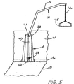
- the holder 1 according to FIGS. 1 to 5 is preferably used for attaching a lifting device H for patients, a so-called patient lift (Fig. 5).
- the holder 1 is designed as a stand that is free-standing on a Floor B can be attached.
- the stand 1 can also be attached to a wall W standing. But it is also possible, the holder H on the floor B and on the wall W to attach, thereby providing optimal support for the holder H is reached.
- the holder 1 has a rectangular rear wall 2 as well these laterally projecting side walls 3 and 4, which the Stand feet 5, 6 have. For this, the bottom ends the side walls 3, 4 bent at right angles to the outside.
- the holder 1 is mirror-symmetrical to its vertical center plane educated.
- the side walls 3, 4 have approximately triangular outline; they are preferably in one piece formed with the rear wall 2.
- the top margins 7, 8 of the sidewalls 3, 4 tapering to the top lie at the same height as the upper edge 9 of the rear wall 2.
- the width of the lower edges 10, 11 of the side walls 3, 4 is larger than the width of the rear wall 2 (Fig. 1, 3).
- the feet 5, 6 have an approximately trapezoidal outline, such that the free longitudinal edges of the feet 5, 6 are shorter than those adjoining the side walls 3, 4 Edges.
- the rear wall 2 and the side walls 3, 4 each have a recess provided on its lower edge 9 ', 10, 11 12 to 14.
- the recess 12 in the rear wall 2 extends across their entire width, while the recesses 13, 14 have only a small width and differ from the rear wall 2 only over a small part of the width of the side walls 3, 4 extend.
- the cutouts 12 have the same height and delimit a stand opening 12 to 14. Is the holder 1 with its rear wall 2 on the Wall W, then through the recesses 12 to 14 for example, a bottom bar attached to the lower end of the wall L (Fig. 5) extend so that the holder 1 in spite of the skirting board L projecting over the wall W. rest perfectly against the wall W with its rear wall 2 can and has a high level of stability.
- the side walls 3, 4 are under one obtuse angle to the rear wall 2, from which the side walls 3, 4 diverging from each other under each run at the same angle. Because of the recesses 13, 14 have the feet 5, 6 distance from the rear wall 2 (Fig. 3).
- the free edges 15 facing away from the rear wall 2, 16 of the feet 5, 6 are perpendicular to the side walls 3, 4, while the opposite edges 15 ', 16' are acute-angled run to the side walls 3 and 4.
- With relative close to the edges 15, 15 ' or 16, 16 ' have feet 5, 6 through openings 17, 18 and 19, 20 for securing parts such as screws and the like, with which the feet 5, 6 are flat holder 1 resting on the floor B on the floor B can be attached.
- the holder 1 can be both free in the room as well as with its rear wall 2 on the wall W to be fitted over the entire surface. In this case the holder 1 is advantageous over other fasteners also attached to the wall. They are through openings 21 to 26 inserted or screwed into the rear wall 2. As shown in FIG. 2, low Distance from the upper and lower edges 9 and 12 respectively Rear wall 2 each provided at the same height Openings 21, 22 and 23, 24 are provided. Halfway up the wall 2 are two additional openings 25 and 26 available. At a distance above openings 23 and 24 and points at a distance below the openings 21 and 22 the rear wall 2 in the area between the side walls 3, 4 Connection parts 27 and 28, which, like FIGS. 2 and 3 each show a dovetail-shaped opening 29, 30 have.
- openings are used to receive a corresponding counterpart (not shown) 41, 42 (Fig. 5) of the lifting device to be secured on the holder 1 H.
- the connecting parts 27 and 28 are relatively small Distance from openings 21, 22 and 23, 24, however at a relatively large distance from the central openings 25, 26. This means that the lift H is relatively wide apart fastening points created, so that he has a secure hold on stand 1.
- the connectors 27, 28 are advantageous on the rear wall 2 releasably attached and lie with a foot piece 32, 33 on the rear wall 2. From the foot pieces 32, 33 stand end pieces 34, 35; 36, 37 before, facing each other Edges 38, 39 converging from the foot piece 32, 33 run and the side faces of the dovetail-shaped Limit openings 29, 30.
- the holder 1 has due to its opposite the rear wall 2 outwardly extending side walls 3, 4 and the feet 5, 6 a high level of stability. He is as a result of this Training on relatively far apart Places supported on floor B. An additional facility and attachment to the wall W ensures one even more secure hold of the lifting device H. With the help the holder 1, the lifting device H can easily can also be attached to a lightweight wall. In this Case transfers the holder when the lifting device is loaded H occurring forces on the side walls 3, 4th and their feet 5, 6 perfectly on the floor. Even if the holder 1 is mounted free-standing on the floor B, it can be the relative acting on the lifting device absorb high forces and hit the ground transfer.
- the lifting device arranged in the holder 1 H (FIG. 5) can easily be pivoted through 180 °, since the load on the side walls 3, 4 or feet 5, 6 supported perfectly over the entire swivel range becomes. The lifting device H is protected in the holder 1 housed, with the holder only relatively little space takes up.
- the lifting device H has a stand 40 (FIG. 5) which the counterparts 41, 42 are attached, which in assembled Location of the lifting device H in the dovetail shape Openings 29, 30 of the connecting parts 27, 28 intervene.
- the stand 40 stands on the floor B. and goes into a gallows arm at the top 43 over, on which a rope 44 or the like Handle 45 is attached.
- the rope 44 can also be in or along the support arm 43 and the stand 40 to a take-up drum be guided so that the rope 44 for adjustment of the handle 45 are wound up or unwound can.
- the stand 40 is in the counterparts 41, 42 rotatably arranged so that it rotated to the extent necessary can be.
Landscapes
- Health & Medical Sciences (AREA)
- Nursing (AREA)
- Life Sciences & Earth Sciences (AREA)
- Animal Behavior & Ethology (AREA)
- General Health & Medical Sciences (AREA)
- Public Health (AREA)
- Veterinary Medicine (AREA)
- Invalid Beds And Related Equipment (AREA)
- Forklifts And Lifting Vehicles (AREA)
- Load-Engaging Elements For Cranes (AREA)
Claims (11)
- Support (1) pour un dispositif de suspension et/ou de levage pour des malades avec au moins une pièce de raccordement (27, 28) à fixer à une paroi (W) ou tel et avec une ouverture d'entrée pour le dispositif de suspension (H),
caractérisé en ce que le support (1) est formé comme montant avec deux pieds (5, 6) en forme de plaque, posés sur le sol (B) à une certaine distance l'un de l'autre et au moins une partie du paroi (2) pour contact et appui à une paroi (W), et en ce que les pieds (5, 6) sont constitués par un bord écarté des parois latérales (3, 4) du support (1). - Support selon la revendication 1,
caractérisé en ce que les pieds (5, 6) sont écartés transversalement, avantageusement orthogonalement aux parois latérales (3, 4). - Support selon revendication 1 ou 2,
caractérisé en ce que au moins l'une des parois latérales, de préférence les deux parois latérales (3, 4) incluent un angle obtus avec la partie du paroi (2) de préférence rectangulaire. - Support selon une des revendications 1 à 3,
caractérisé en ce que les parois latérales (3, 4) ont le même contour, à peu près triangulaire, et se rétréssissent de préférence vers le haut. - Support selon une des revendications 1 à 4,
caractérisé en ce que les parois latérales (3, 4) ont des bords supérieurs (7, 8), lesquels sont situés dans un plan commun de préférence horizontal avec un bord supérieur (9) de la partie du paroi (2), et qu'avantageusement les bords supérieurs (7, 8) des parois latérales (3, 4) continuent par le bord supérieur de la partie du paroi (2). - Support selon une des revendications 1 á 5,
caractérisé en ce que la largeur maximale des parois latérales (3, 4), prévue dans la zone des bords inférieurs (10, 11) est plus grande que la largeur de la partie du paroi (2). - Support selon une des revendications 1 à 6,
caractérisé en ce que la partie du paroi (2) et/ou les parois latérales (3, 4) comprennent un évidement (12 à 14), prévu respectivement à leur bord inférieur (9', 10, 11). - Support selon revendication 7,
caractérisé en ce que l'évidement (12) de la partie du paroi (2) s'étend sur la largeur totale de celle-ci. - Support selon revendication 7 ou 8,
caractérisé en ce que les évidements (13, 14) des parois latérales (3, 4) sont plus étroits que l'évidement (12) de la partie du paroi (2). - Support selon une des revendications 1 à 9,
caractérisé en ce que au moins les pieds (5, 6), de préférence les pieds et la partie du paroi (2) comprennent des ouvertures (15 à 18; 21 à 26) pour des moyens de fixation que vis ou autres. - Support selon une des revendications 1 à 10,
caractérisé en ce que la partie du paroi (2) comprend deux éléments d'attache (27, 28), superposés à une certaine distance pour une pièce d'accouplement du dispositif de suspension (H), lesquels sont fixés de façon démontable, de préférence vissés à la partie du paroi (2).
Applications Claiming Priority (2)
| Application Number | Priority Date | Filing Date | Title |
|---|---|---|---|
| DE29615004U | 1996-08-29 | ||
| DE29615004U DE29615004U1 (de) | 1996-08-29 | 1996-08-29 | Halter für eine Trag- und/oder Hebevorrichtung, insbesondere eine Hebevorrichtung für Patienten |
Publications (2)
| Publication Number | Publication Date |
|---|---|
| EP0826357A1 EP0826357A1 (fr) | 1998-03-04 |
| EP0826357B1 true EP0826357B1 (fr) | 2002-12-04 |
Family
ID=8028492
Family Applications (1)
| Application Number | Title | Priority Date | Filing Date |
|---|---|---|---|
| EP97112825A Expired - Lifetime EP0826357B1 (fr) | 1996-08-29 | 1997-07-25 | Support pour dispositif de maintien ou de levage, en particulier système de levage pour patients |
Country Status (3)
| Country | Link |
|---|---|
| EP (1) | EP0826357B1 (fr) |
| AT (1) | ATE228812T1 (fr) |
| DE (2) | DE29615004U1 (fr) |
Family Cites Families (3)
| Publication number | Priority date | Publication date | Assignee | Title |
|---|---|---|---|---|
| BE811502A (nl) * | 1974-02-25 | 1974-06-17 | Orthopedische ziekenoprichter voor bevestiging aan de muur | |
| DE8613814U1 (de) * | 1986-05-22 | 1986-08-14 | Meinhardt, Werner, Dipl.-Ing., 2087 Hasloh | Haltegestell |
| DE29614203U1 (de) * | 1996-08-16 | 1996-10-24 | Cavelius, Stefan, 66798 Wallerfangen | Befestigungsstange für Gymnastikbänder |
-
1996
- 1996-08-29 DE DE29615004U patent/DE29615004U1/de not_active Expired - Lifetime
-
1997
- 1997-07-25 DE DE59708868T patent/DE59708868D1/de not_active Expired - Fee Related
- 1997-07-25 EP EP97112825A patent/EP0826357B1/fr not_active Expired - Lifetime
- 1997-07-25 AT AT97112825T patent/ATE228812T1/de not_active IP Right Cessation
Also Published As
| Publication number | Publication date |
|---|---|
| ATE228812T1 (de) | 2002-12-15 |
| DE59708868D1 (de) | 2003-01-16 |
| EP0826357A1 (fr) | 1998-03-04 |
| DE29615004U1 (de) | 1996-10-24 |
Similar Documents
| Publication | Publication Date | Title |
|---|---|---|
| DE3409992A1 (de) | Vorrichtung zum abhaengen einer zwischendecke | |
| WO2007071765A1 (fr) | Systeme d'etagere a element support coulissant en continu dans un rail de paroi | |
| EP0826357B1 (fr) | Support pour dispositif de maintien ou de levage, en particulier système de levage pour patients | |
| DE2921636A1 (de) | Geraet mit hubvorrichtung zum klettern an einer wand | |
| DE3121869A1 (de) | Haltekonsole zur loesbaren anbringung von gegenstaenden an einer wandschiene | |
| DE4109374C1 (fr) | ||
| DE1297399B (de) | Aufhaengevorrichtung fuer Tierkaefige | |
| DE29613772U1 (de) | Abnehmbar anzubringendes Aluminium-Montagegerüst mit Geländer für den Einsatz auf Dächern mit beliebiger Dachneigung | |
| EP4103015B1 (fr) | Dispositif de suspension | |
| DE202022100412U1 (de) | Blumenkasten | |
| EP0331976A1 (fr) | Support d'appareil | |
| DE10210778B4 (de) | Gehäuse oder Gestell mit einer Kabelführungsvorrichtung | |
| DE7822671U1 (de) | Transportvorrichtung für Sportgeräte | |
| DE20220848U1 (de) | Gehäuse oder Gestell mit einer Kabelführungsvorrichtung | |
| DE2544013A1 (de) | Traeger zur unterstuetzung einer ablage insbesondere fuer zeitschriften, buecher o.dgl. | |
| DE2261036C3 (de) | Anordnung an Arbeitstischen zur Aufstellung von Geräten | |
| DE3007229A1 (de) | Kabelverteiler | |
| DE3321419C2 (fr) | ||
| DE202019100583U1 (de) | Arbeitstisch | |
| EP0405228B1 (fr) | Dispositif de fixation de sièges démontables ou de supports de sièges pour tribunes | |
| DE29720976U1 (de) | Arbeitsmöbel | |
| DE3201999C2 (de) | Vorrichtung zum Aufhängen von langgestreckten Gegenständen | |
| DE3111806C2 (de) | Haltevorrichtung, für flache, lange Gegenstände, insbesondere für ein Segelbrett | |
| DE102022101705A1 (de) | Blumenkasten | |
| DE8209713U1 (de) | Schildträger für Typenschilder oder andere Kennzeichnungen, insbesondere in Kraftwerken |
Legal Events
| Date | Code | Title | Description |
|---|---|---|---|
| PUAI | Public reference made under article 153(3) epc to a published international application that has entered the european phase |
Free format text: ORIGINAL CODE: 0009012 |
|
| AK | Designated contracting states |
Kind code of ref document: A1 Designated state(s): AT BE CH DE DK FI FR GB IT LI SE |
|
| 17P | Request for examination filed |
Effective date: 19980609 |
|
| AKX | Designation fees paid |
Free format text: AT BE CH DE DK FI FR GB IT LI SE |
|
| RBV | Designated contracting states (corrected) |
Designated state(s): AT BE CH DE DK FI FR GB IT LI SE |
|
| 17Q | First examination report despatched |
Effective date: 20010115 |
|
| GRAG | Despatch of communication of intention to grant |
Free format text: ORIGINAL CODE: EPIDOS AGRA |
|
| GRAG | Despatch of communication of intention to grant |
Free format text: ORIGINAL CODE: EPIDOS AGRA |
|
| GRAH | Despatch of communication of intention to grant a patent |
Free format text: ORIGINAL CODE: EPIDOS IGRA |
|
| RAP1 | Party data changed (applicant data changed or rights of an application transferred) |
Owner name: AACURAT GMBH |
|
| GRAH | Despatch of communication of intention to grant a patent |
Free format text: ORIGINAL CODE: EPIDOS IGRA |
|
| GRAA | (expected) grant |
Free format text: ORIGINAL CODE: 0009210 |
|
| AK | Designated contracting states |
Kind code of ref document: B1 Designated state(s): AT BE CH DE DK FI FR GB IT LI SE |
|
| PG25 | Lapsed in a contracting state [announced via postgrant information from national office to epo] |
Ref country code: IT Free format text: LAPSE BECAUSE OF FAILURE TO SUBMIT A TRANSLATION OF THE DESCRIPTION OR TO PAY THE FEE WITHIN THE PRE;WARNING: LAPSES OF ITALIAN PATENTS WITH EFFECTIVE DATE BEFORE 2007 MAY HAVE OCCURRED AT ANY TIME BEFORE 2007. THE CORRECT EFFECTIVE DATE MAY BE DIFFERENT FROM THE ONE RECORDED.SCRIBED TIME-LIMIT Effective date: 20021204 Ref country code: GB Free format text: LAPSE BECAUSE OF FAILURE TO SUBMIT A TRANSLATION OF THE DESCRIPTION OR TO PAY THE FEE WITHIN THE PRESCRIBED TIME-LIMIT Effective date: 20021204 Ref country code: FR Free format text: LAPSE BECAUSE OF FAILURE TO SUBMIT A TRANSLATION OF THE DESCRIPTION OR TO PAY THE FEE WITHIN THE PRESCRIBED TIME-LIMIT Effective date: 20021204 Ref country code: FI Free format text: LAPSE BECAUSE OF FAILURE TO SUBMIT A TRANSLATION OF THE DESCRIPTION OR TO PAY THE FEE WITHIN THE PRESCRIBED TIME-LIMIT Effective date: 20021204 |
|
| REF | Corresponds to: |
Ref document number: 228812 Country of ref document: AT Date of ref document: 20021215 Kind code of ref document: T |
|
| REG | Reference to a national code |
Ref country code: GB Ref legal event code: FG4D Free format text: NOT ENGLISH |
|
| REG | Reference to a national code |
Ref country code: CH Ref legal event code: EP |
|
| REF | Corresponds to: |
Ref document number: 59708868 Country of ref document: DE Date of ref document: 20030116 |
|
| PG25 | Lapsed in a contracting state [announced via postgrant information from national office to epo] |
Ref country code: SE Free format text: LAPSE BECAUSE OF FAILURE TO SUBMIT A TRANSLATION OF THE DESCRIPTION OR TO PAY THE FEE WITHIN THE PRESCRIBED TIME-LIMIT Effective date: 20030304 Ref country code: DK Free format text: LAPSE BECAUSE OF FAILURE TO SUBMIT A TRANSLATION OF THE DESCRIPTION OR TO PAY THE FEE WITHIN THE PRESCRIBED TIME-LIMIT Effective date: 20030304 |
|
| GBV | Gb: ep patent (uk) treated as always having been void in accordance with gb section 77(7)/1977 [no translation filed] |
Effective date: 20021204 |
|
| PG25 | Lapsed in a contracting state [announced via postgrant information from national office to epo] |
Ref country code: AT Free format text: LAPSE BECAUSE OF NON-PAYMENT OF DUE FEES Effective date: 20030725 |
|
| PG25 | Lapsed in a contracting state [announced via postgrant information from national office to epo] |
Ref country code: LI Free format text: LAPSE BECAUSE OF NON-PAYMENT OF DUE FEES Effective date: 20030731 Ref country code: CH Free format text: LAPSE BECAUSE OF NON-PAYMENT OF DUE FEES Effective date: 20030731 Ref country code: BE Free format text: LAPSE BECAUSE OF NON-PAYMENT OF DUE FEES Effective date: 20030731 |
|
| PGFP | Annual fee paid to national office [announced via postgrant information from national office to epo] |
Ref country code: DE Payment date: 20030930 Year of fee payment: 7 |
|
| PLBE | No opposition filed within time limit |
Free format text: ORIGINAL CODE: 0009261 |
|
| STAA | Information on the status of an ep patent application or granted ep patent |
Free format text: STATUS: NO OPPOSITION FILED WITHIN TIME LIMIT |
|
| EN | Fr: translation not filed | ||
| 26N | No opposition filed |
Effective date: 20030905 |
|
| BERE | Be: lapsed |
Owner name: *AACURAT G.M.B.H. Effective date: 20030731 |
|
| REG | Reference to a national code |
Ref country code: CH Ref legal event code: PL |
|
| PG25 | Lapsed in a contracting state [announced via postgrant information from national office to epo] |
Ref country code: DE Free format text: LAPSE BECAUSE OF NON-PAYMENT OF DUE FEES Effective date: 20050201 |