EP0826484A2 - Mécanisme de centrage pour machine de vulcanisation de pneus - Google Patents
Mécanisme de centrage pour machine de vulcanisation de pneus Download PDFInfo
- Publication number
- EP0826484A2 EP0826484A2 EP97111537A EP97111537A EP0826484A2 EP 0826484 A2 EP0826484 A2 EP 0826484A2 EP 97111537 A EP97111537 A EP 97111537A EP 97111537 A EP97111537 A EP 97111537A EP 0826484 A2 EP0826484 A2 EP 0826484A2
- Authority
- EP
- European Patent Office
- Prior art keywords
- center post
- center
- ring
- clamp ring
- tire
- Prior art date
- Legal status (The legal status is an assumption and is not a legal conclusion. Google has not performed a legal analysis and makes no representation as to the accuracy of the status listed.)
- Granted
Links
- 230000003028 elevating effect Effects 0.000 claims abstract description 33
- 125000006850 spacer group Chemical group 0.000 claims abstract description 26
- 238000010438 heat treatment Methods 0.000 description 10
- 239000011324 bead Substances 0.000 description 8
- 238000004073 vulcanization Methods 0.000 description 6
- 230000003247 decreasing effect Effects 0.000 description 5
- 238000009423 ventilation Methods 0.000 description 5
- 239000012530 fluid Substances 0.000 description 3
- 238000009434 installation Methods 0.000 description 3
- 230000007423 decrease Effects 0.000 description 2
- 230000017525 heat dissipation Effects 0.000 description 2
- 230000001965 increasing effect Effects 0.000 description 2
- 239000011261 inert gas Substances 0.000 description 2
- 238000001816 cooling Methods 0.000 description 1
- 239000007789 gas Substances 0.000 description 1
- 239000010720 hydraulic oil Substances 0.000 description 1
- 230000002093 peripheral effect Effects 0.000 description 1
- XLYOFNOQVPJJNP-UHFFFAOYSA-N water Substances O XLYOFNOQVPJJNP-UHFFFAOYSA-N 0.000 description 1
Images

Classifications
-
- B—PERFORMING OPERATIONS; TRANSPORTING
- B29—WORKING OF PLASTICS; WORKING OF SUBSTANCES IN A PLASTIC STATE IN GENERAL
- B29C—SHAPING OR JOINING OF PLASTICS; SHAPING OF MATERIAL IN A PLASTIC STATE, NOT OTHERWISE PROVIDED FOR; AFTER-TREATMENT OF THE SHAPED PRODUCTS, e.g. REPAIRING
- B29C35/00—Heating, cooling or curing, e.g. crosslinking or vulcanising; Apparatus therefor
- B29C35/02—Heating or curing, e.g. crosslinking or vulcanizing during moulding, e.g. in a mould
-
- B—PERFORMING OPERATIONS; TRANSPORTING
- B29—WORKING OF PLASTICS; WORKING OF SUBSTANCES IN A PLASTIC STATE IN GENERAL
- B29D—PRODUCING PARTICULAR ARTICLES FROM PLASTICS OR FROM SUBSTANCES IN A PLASTIC STATE
- B29D30/00—Producing pneumatic or solid tyres or parts thereof
- B29D30/06—Pneumatic tyres or parts thereof (e.g. produced by casting, moulding, compression moulding, injection moulding, centrifugal casting)
- B29D30/0601—Vulcanising tyres; Vulcanising presses for tyres
- B29D30/0645—Devices for inserting vulcanising cores, i.e. bladders, into the tyres; Closing the press in combination herewith
-
- B—PERFORMING OPERATIONS; TRANSPORTING
- B29—WORKING OF PLASTICS; WORKING OF SUBSTANCES IN A PLASTIC STATE IN GENERAL
- B29C—SHAPING OR JOINING OF PLASTICS; SHAPING OF MATERIAL IN A PLASTIC STATE, NOT OTHERWISE PROVIDED FOR; AFTER-TREATMENT OF THE SHAPED PRODUCTS, e.g. REPAIRING
- B29C33/00—Moulds or cores; Details thereof or accessories therefor
- B29C33/30—Mounting, exchanging or centering
- B29C33/303—Mounting, exchanging or centering centering mould parts or halves, e.g. during mounting
- B29C33/304—Mounting, exchanging or centering centering mould parts or halves, e.g. during mounting centering cores
Definitions
- the present invention relates to a center mechanism of a tire vulcanizer.
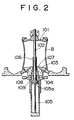
- reference character B denotes a bladder
- 101 denotes an upper clamp ring for holding the upper opening end of the bladder B
- 102 denotes a center post detachably fixing the upper clamp ring 101 at the upper end portion thereof
- 103 denotes a lower clamp ring for holding the lower opening end of the bladder B
- 104 denotes a lower ring detachably fixing the lower clamp ring 103
- 105 denotes a center post elevating cylinder
- 106 denotes a second piston rod for the center post elevating cylinder 105
- 107, 108, and 109 denote seal members.
- the center post 102 is fixed to a piston 105a of the center post elevating cylinder 105, and the second piston rod 106 is fitted on the outer periphery of the center post 102 and inserted, in such a manner as to be movable vertically, into a through hole formed in the center of the lower ring 104.
- the second piston rod 106 has a function of restricting the elevation stroke of the center post 102.
- FIG. 3 there is a tendency to use a center mechanism of a tire vulcaniser shown in FIG. 3 (for example, the center mechanism of a tire vulcanizer disclosed in Japanese Patent Provisional Publication No. 3-274113 (No. 274113/1991)).
- reference character T denotes a tire being vulcanized
- B denotes a bladder
- 201 and 203 denote upper and lower clamp rings for holding the upper and lower opening ends of the bladder B, respectively
- 204 denotes a lower ring detachably fixing the lower clamp ring 203
- 202 denotes a center post inserted, in such a manner as to be movable vertically, into a through hole formed in the center of the lower ring 204.
- To the upper end portion of the center post 202 is detachably fixed the upper clamp ring 201.
- Reference numeral 207 denotes a seal member interposed between the lower ring 204 and the center post 202
- 205 denotes a center post elevating cylinder fixed to the lower ring 204 via a spacer 206.
- the upper end of a piston rod 205a of the cylinder 205 is connected to the lower end of the center post 202 by screwing.
- the presence of the spacer 206 can decrease the amount of heat transfer to the center post elevating cylinder 205.
- a pipe (not shown) is connected to the spacer 206 so that the heating/pressurizing medium leaking due to wear of the seal member 207 can be discharged to the outside of the machine through the pipe connected to the spacer 206. Therefore, the inflow of the heating/pressurising medium into the center post elevating cylinder 205 can be eliminated completely, so that the above problem can be solved.
- a hydraulic oil can be used as a working fluid for the center post elevating cylinder 205.
- the center mechanism of a tire vulcaniser shown in FIG. 3 has a problem in that the installation pit for the tire vulcanizer must be deeper by the length of the spacer 206.
- the present invention was made to solve the above problems, and accordingly an object thereof is to provide a center mechanism of a tire vulcaniser, in which the depth of installation pit for the tire vulcaniser can be decreased significantly.
- the present invention provides a center mechanism of a tire vulcanizer, having an upper clamp ring for holding the upper opening end of a bladder, a lower clamp ring for holding the lower opening end of the bladder, a lower ring on the lower mold side supporting the lower clamp ring, a spacer installed to the lower ring and having a ventilating portion, and a center post elevating cylinder installed to the spacer, in which the extending portion of piston rod of the center post elevating cylinder is made a center post, the center post is inserted, in such a manner as to be movable vertically, into a through hole formed in the center of the lower ring and the lower clamp ring, and the upper clamp ring is fixed to the upper end portion of center post protruding upward from the through hole of the lower clamp ring (claim 1).
- the piston rod of the center post elevating cylinder and the center post may be formed integrally (claim 2).
- the lower end portion of the spacer may be connected to a flange provided at the vertical intermediate position of the center post elevating cylinder (claim 3).
- a tire vulcanizer may be one having a center mechanism according to any one of claims 1 to 3 (claim 4).
- a center mechanism of a tire vulcanizer in accordance with the present invention has an upper clamp ring for holding the upper opening end of a bladder, a lower clamp ring for holding the lower opening end of the bladder, a lower ring on the lower mold side supporting the lower clamp ring, a spacer installed to the lower ring and having a ventilating portion, and a center post elevating cylinder installed to the spacer.
- the extending portion of piston rod of the center post elevating cylinder is made a center post, the center post is inserted, in such a manner as to be movable vertically, into a through hole formed in the center of the lower ring and the lower clamp ring, and the upper clamp ring is fixed to the upper end portion of center post protruding upward from the through hole of the lower clamp ring. Since the extending portion of piston rod of the center post elevating cylinder is made a center post, the distance between the lower ring and the center post elevating cylinder can be decreased. In addition, since the spacer is provided with the ventilating portion to accelerate heat dissipation, there is no need for increasing the length of the spacer, so that the depth of installation pit for the tire vulcaniser can be decreased significantly.
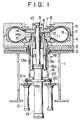
- a center mechanism of a tire vulcanizer in accordance with the present invention will be described below with reference to one embodiment shown in FIG. 1.
- reference character T denotes a tire being vulcanized
- B denotes a bladder
- 1 denotes a base for a tire vulcanizer body frame
- 3 denotes a lower hot plate fixed to the base 1 via a heat insulating plate 2 by means of bolts etc.
- 4 denotes a lower mold fixed to the lower hot plate 3 by means of bolts etc.
- 5 denotes an upper mold fixed to a bolster plate (not shown), which is assembled to the body frame in such a manner as to be movable vertically, via the heat insulating plate 2 and the upper hot plate (not shown) by means of bolts etc.
- 6 denotes an upper bead ring bolted to the upper mold 5.
- Reference numeral 8 denotes an upper clamp ring for holding the upper opening end of the bladder B. By bolting a clamp plate 7 to the upper clamp ring 8, the upper opening end of the bladder B can be held.
- Reference numeral 9 denotes a lock ring capable of being divided into two pieces in the circumferential direction
- 10 denotes a center post (a piston rod of a center post elevating cylinder 19) fixing the upper clamp ring 8 at the upper end portion thereof.
- the upper clamp ring 8 is fitted onto the upper end portion of the center post 10, and unified by bolting the two-piece lock ring 9.
- a seal member is interposed between the center post 10 and the upper clamp ring 8.
- Reference numeral 12 denotes a lower clamp ring for holding the lower opening end of the bladder B. By bolting the lower bead ring 11 to the lower clamp ring 12, the lower opening end of the bladder B can be held.
- Reference numeral 13 denotes a lower ring fixing the lower clamp ring 12 by screwing at the outer periphery thereof.
- a seal member is interposed between the lower ring 13 and the lower clamp ring 12.
- Reference numeral 15 denotes an assembly of a seal member and a bushing, inserted in the inner peripheral portion of the lower ring 13.
- the assembly 15 is prevented from coming off by a flange 14 bolted to the lower ring 13.
- the center post 10 is inserted in such a manner as to be movable vertically. That is, a through hole 23 for inserting the center post 10 is formed in the center of the lower ring 13 and the lower clamp ring 12.
- the upper end of a heating/pressurizing medium passage 13a provided in the lower ring 13 is connected to the interior of the bladder B via a nozzle 14a provided in the flange 14, and the lower end of the heating/pressurizing medium passage 13a is connected to a heating/pressurizing medium supply/discharge device (not shown) via a pipe 13b fixed by screwing etc.
- Reference numeral 16 denotes a spacer fixed to the outer periphery of the lower ring 13 by screwing etc. At the vertical intermediate portion of the spacer 16, a ventilation window 16a, which is a ventilating portion, for effecting ventilation is provided. Ventilation may be effected by using a cooling fan or the like.
- Reference numeral 19 denotes a center post elevating cylinder provided with a flange 19a at the vertical intermediate portion thereof.
- the flange 19a of the cylinder 19 and the lower end portion of the spacer 16 are bolted to each other. Therefore, by actuating the center post elevating cylinder 19 to raise/lower the center post (the piston rod of the center post elevating cylinder 19), the bladder B can be expanded or contracted vertically.
- Reference numeral 18 denotes a guide tube provided at the inner periphery of the lower hot plate 3.
- a bushing 17 is inserted in the guide tube 18 and fixed to the inner periphery thereof. Inside the bushing 17, the lower ring 13 integral with the spacer 16 is inserted in such a manner as to be movable vertically.
- Reference numeral 21 denotes a bead lift cylinder bolted to a bracket 20 fixed to the base 1.
- the upper end of a piston rod 21a of the bead lift cylinder 21 is connected to a flange 22 of the spacer 16. Therefore, by actuating the bead lift cylinder 21, the center post elevating cylinder 19, spacer 16, lower ring 13, and lower bead ring 11 can be raised or lowered.
- the upper part of the center post 10, lower ring 13, etc. come in contact, via the bladder B, with the heating/pressurising medium supplied into the interior of the tire T, so that these elements are heated to a temperature close to 200°C.
- This heat of about 200°C is dissipated from the portion of center post 10 protruding below the lower ring 13, so that the temperature lowers before the heat reaches the center post elevating cylinder 19.
- the heat dissipation is accelerated by the ventilation through the ventilation window 16a provided in the spacer 16, and the amount of heat transfer through the spacer 16 decreases. Therefore, the temperature of the center post elevating cylinder 19 becomes a temperature lower than the allowable temperature for the working fluid of the cylinder 19 and the seal member.
- the distance between the center post elevating cylinder 19 and the lower ring 13 is predetermined so that the temperature of the center post elevating cylinder 19 is not higher than the allowable temperature for the working fluid of the cylinder 19 and the seal member.
- the heating/pressurizing medium in the tire T is discharged in the same manner as the conventional manner, and then the upper mold 5 is raised.
- the interior of the bladder B is made vacuum, and the center post elevating cylinder 19 is actuated, whereby the upper clamp ring 8 is raised to extend the bladder B while decreasing the diameter thereof to remove the tire T.
- the bead lift cylinder 21 is actuated to raise the lower bead ring 11, whereby the tire T is separated from the lower mold 4 and raised.
- the tire T is taken out of the machine by conventional means, and a tire T to be vulcanised next is loaded.
- the loaded tire T is shaped, and the upper mold 5 is lowered.
- the heating/pressurising medium is poured into the tire T via the bladder B.
- the vulcanization process is started, and the above operation is repeated.
- the present invention can be applied to a center mechanism of a tire vulcanisation of other types, for example, to a center mechanism of a tire vulcanization of a type such that the bladder B is stored in a well in loading/unloading the tire.
Landscapes
- Engineering & Computer Science (AREA)
- Mechanical Engineering (AREA)
- Physics & Mathematics (AREA)
- Health & Medical Sciences (AREA)
- Oral & Maxillofacial Surgery (AREA)
- Thermal Sciences (AREA)
- Moulds For Moulding Plastics Or The Like (AREA)
- Heating, Cooling, Or Curing Plastics Or The Like In General (AREA)
Applications Claiming Priority (3)
| Application Number | Priority Date | Filing Date | Title |
|---|---|---|---|
| JP23316396 | 1996-09-03 | ||
| JP233163/96 | 1996-09-03 | ||
| JP23316396A JP3300744B2 (ja) | 1996-09-03 | 1996-09-03 | タイヤ加硫機の中心機構 |
Publications (3)
| Publication Number | Publication Date |
|---|---|
| EP0826484A2 true EP0826484A2 (fr) | 1998-03-04 |
| EP0826484A3 EP0826484A3 (fr) | 1999-06-30 |
| EP0826484B1 EP0826484B1 (fr) | 2002-10-02 |
Family
ID=16950717
Family Applications (1)
| Application Number | Title | Priority Date | Filing Date |
|---|---|---|---|
| EP97111537A Expired - Lifetime EP0826484B1 (fr) | 1996-09-03 | 1997-07-08 | Mécanisme de centrage pour machine de vulcanisation de pneus |
Country Status (6)
| Country | Link |
|---|---|
| US (1) | US5853769A (fr) |
| EP (1) | EP0826484B1 (fr) |
| JP (1) | JP3300744B2 (fr) |
| KR (1) | KR100232338B1 (fr) |
| CN (1) | CN1062213C (fr) |
| DE (1) | DE69715995T2 (fr) |
Cited By (1)
| Publication number | Priority date | Publication date | Assignee | Title |
|---|---|---|---|---|
| CN106671321A (zh) * | 2017-01-20 | 2017-05-17 | 华澳轮胎设备科技(苏州)股份有限公司 | 一种具有分体式定位环的硫化机中心机构及轮胎硫化机 |
Families Citing this family (11)
| Publication number | Priority date | Publication date | Assignee | Title |
|---|---|---|---|---|
| JP4387047B2 (ja) * | 2000-07-13 | 2009-12-16 | 株式会社神戸製鋼所 | 中心機構 |
| KR100382289B1 (ko) * | 2000-10-07 | 2003-05-01 | 금호산업 주식회사 | 타이어 가류기용 센터 포스트 내부의 증기 분출 구조 |
| KR20030095466A (ko) * | 2002-06-10 | 2003-12-24 | 한국타이어 주식회사 | 타이어 가류기의 그린타이어 센터링 장치 |
| DE602004026314D1 (de) * | 2003-07-25 | 2010-05-12 | Fuji Shoji Co Ltd | Reifenvulkanisierverfahren und vulkanisiervorrichtung zur durchführung des verfahrens |
| US20080084007A1 (en) * | 2006-10-05 | 2008-04-10 | Carlisle Intangible Company | Low aspect ratio tire curing bladder |
| JP5469361B2 (ja) * | 2009-04-10 | 2014-04-16 | 三菱重工マシナリーテクノロジー株式会社 | タイヤ加硫機の中心機構 |
| CN101537718A (zh) * | 2009-04-27 | 2009-09-23 | 余延博 | 轮胎热翻中心冲气机构 |
| KR101160235B1 (ko) | 2010-08-31 | 2012-06-26 | 금호타이어 주식회사 | 타이어 가류 장치 |
| CN102672859B (zh) * | 2012-05-09 | 2016-11-02 | 青岛康宏安工贸有限公司 | 双模高效斜交轮胎全自动硫化机 |
| KR101356577B1 (ko) | 2012-11-09 | 2014-02-04 | 한국타이어 주식회사 | 타이어 가류기의 중심기구 배관 연결장치 |
| KR101414517B1 (ko) * | 2012-11-13 | 2014-07-04 | 한국타이어 주식회사 | 열손실을 방지한 타이어 가류금형 |
Family Cites Families (9)
| Publication number | Priority date | Publication date | Assignee | Title |
|---|---|---|---|---|
| US106280A (en) * | 1870-08-09 | James t | ||
| DE1729860A1 (de) * | 1964-06-26 | 1971-07-08 | Karl Zaengl | Verfahren zum Einbringen eines Blaehbalges in einem zu vulkanisierenden Reifen und Vulkanisierpresse zum Durchfuehren des Verfahrens |
| US3632712A (en) * | 1969-04-10 | 1972-01-04 | Gen Tire & Rubber Co | Method for curing of pneumatic tires |
| US4338069A (en) * | 1980-04-09 | 1982-07-06 | Nrm Corporation | Tire press |
| JPS57150556A (en) * | 1981-03-13 | 1982-09-17 | Kobe Steel Ltd | Center mechanism for tire vulcanizer |
| JPS5866934A (ja) * | 1981-10-16 | 1983-04-21 | Fuji Photo Film Co Ltd | 放射線画像情報記録読取装置 |
| US4768937A (en) * | 1987-02-02 | 1988-09-06 | Nrm Corporation | Tire curing press |
| JPH0637058B2 (ja) * | 1989-08-02 | 1994-05-18 | 三菱重工業株式会社 | タイヤ加硫機の中心機構 |
| JP2647531B2 (ja) * | 1990-03-26 | 1997-08-27 | 三菱重工業株式会社 | タイヤ加硫機の中心機構 |
-
1996
- 1996-09-03 JP JP23316396A patent/JP3300744B2/ja not_active Expired - Fee Related
-
1997
- 1997-07-07 US US08/889,176 patent/US5853769A/en not_active Expired - Lifetime
- 1997-07-08 DE DE69715995T patent/DE69715995T2/de not_active Expired - Lifetime
- 1997-07-08 EP EP97111537A patent/EP0826484B1/fr not_active Expired - Lifetime
- 1997-09-01 CN CN97117563A patent/CN1062213C/zh not_active Expired - Lifetime
- 1997-09-03 KR KR1019970045641A patent/KR100232338B1/ko not_active Expired - Lifetime
Cited By (2)
| Publication number | Priority date | Publication date | Assignee | Title |
|---|---|---|---|---|
| CN106671321A (zh) * | 2017-01-20 | 2017-05-17 | 华澳轮胎设备科技(苏州)股份有限公司 | 一种具有分体式定位环的硫化机中心机构及轮胎硫化机 |
| CN106671321B (zh) * | 2017-01-20 | 2022-11-15 | 华澳轮胎设备科技(苏州)股份有限公司 | 一种具有分体式定位环的硫化机中心机构及轮胎硫化机 |
Also Published As
| Publication number | Publication date |
|---|---|
| CN1062213C (zh) | 2001-02-21 |
| JPH1076529A (ja) | 1998-03-24 |
| US5853769A (en) | 1998-12-29 |
| DE69715995D1 (de) | 2002-11-07 |
| EP0826484B1 (fr) | 2002-10-02 |
| KR19980024308A (ko) | 1998-07-06 |
| CN1178158A (zh) | 1998-04-08 |
| DE69715995T2 (de) | 2003-06-18 |
| JP3300744B2 (ja) | 2002-07-08 |
| KR100232338B1 (ko) | 1999-12-01 |
| EP0826484A3 (fr) | 1999-06-30 |
Similar Documents
| Publication | Publication Date | Title |
|---|---|---|
| EP0826484B1 (fr) | Mécanisme de centrage pour machine de vulcanisation de pneus | |
| US2997738A (en) | Apparatus and method for positioning a tire in a curing press | |
| US3976409A (en) | Tire curing press center mechanism | |
| KR20010005699A (ko) | 공압 타이어 제조 방법 | |
| CN116829341A (zh) | 热压机及在热压机中真空硫化车辆轮胎的方法 | |
| EP1743755B1 (fr) | Procédé de vulcanisation des pneus et procédé de réglage du processus de vulcanisation des pneus | |
| US5961913A (en) | Device and process for vulcanizing tires | |
| US3584335A (en) | Tire curing press with loader and removal devices | |
| US5151242A (en) | Method for vulcanizing elastomer products and apparatus therefor | |
| KR0138108B1 (ko) | 자동차 공기타이어 경화를 위한 방법 및 장치 | |
| JP5270241B2 (ja) | タイヤ加硫機の中心機構、およびタイヤ加硫機のモールド操作方法 | |
| US20220143942A1 (en) | Tire vulcanization device and method | |
| WO2018029725A1 (fr) | Dispositif de vulcanisation de pneumatique et procédé d'assemblage de dispositif de vulcanisation de pneumatique | |
| JP3701087B2 (ja) | タイヤ加硫方法および装置 | |
| US4446093A (en) | "Piggyback" heat exchanger for dome presses | |
| JP3847463B2 (ja) | 空気ばね用ダイヤフラムの加硫金型 | |
| EP0455126B1 (fr) | Mécanisme de centrage pour machine de vulcanisation de pneus | |
| CN206216982U (zh) | 轮胎硫化用模具 | |
| JP6662597B2 (ja) | タイヤ加硫用金型及びタイヤ製造方法 | |
| EP0669202A2 (fr) | Presse de vulcanization de pneus | |
| KR850002228Y1 (ko) | 타이어가황기의 브래더(加硫機의 bladder) 조작장치 | |
| US3581345A (en) | Tire curing press bladder assembly | |
| US2339541A (en) | Method of vulcanization | |
| US4239723A (en) | Tire mold press operating method | |
| GB2033825A (en) | Tyre mould press |
Legal Events
| Date | Code | Title | Description |
|---|---|---|---|
| PUAI | Public reference made under article 153(3) epc to a published international application that has entered the european phase |
Free format text: ORIGINAL CODE: 0009012 |
|
| 17P | Request for examination filed |
Effective date: 19970708 |
|
| AK | Designated contracting states |
Kind code of ref document: A2 Designated state(s): DE FR GB IT |
|
| AX | Request for extension of the european patent |
Free format text: AL;LT;LV;RO;SI |
|
| PUAL | Search report despatched |
Free format text: ORIGINAL CODE: 0009013 |
|
| AK | Designated contracting states |
Kind code of ref document: A3 Designated state(s): AT BE CH DE DK ES FI FR GB GR IE IT LI LU MC NL PT SE |
|
| AX | Request for extension of the european patent |
Free format text: AL;LT;LV;RO;SI |
|
| AKX | Designation fees paid |
Free format text: DE FR GB IT |
|
| 17Q | First examination report despatched |
Effective date: 20010117 |
|
| GRAG | Despatch of communication of intention to grant |
Free format text: ORIGINAL CODE: EPIDOS AGRA |
|
| GRAG | Despatch of communication of intention to grant |
Free format text: ORIGINAL CODE: EPIDOS AGRA |
|
| GRAH | Despatch of communication of intention to grant a patent |
Free format text: ORIGINAL CODE: EPIDOS IGRA |
|
| GRAH | Despatch of communication of intention to grant a patent |
Free format text: ORIGINAL CODE: EPIDOS IGRA |
|
| GRAA | (expected) grant |
Free format text: ORIGINAL CODE: 0009210 |
|
| AK | Designated contracting states |
Kind code of ref document: B1 Designated state(s): DE FR GB IT |
|
| REG | Reference to a national code |
Ref country code: GB Ref legal event code: FG4D |
|
| REF | Corresponds to: |
Ref document number: 69715995 Country of ref document: DE Date of ref document: 20021107 |
|
| ET | Fr: translation filed | ||
| PLBE | No opposition filed within time limit |
Free format text: ORIGINAL CODE: 0009261 |
|
| STAA | Information on the status of an ep patent application or granted ep patent |
Free format text: STATUS: NO OPPOSITION FILED WITHIN TIME LIMIT |
|
| 26N | No opposition filed |
Effective date: 20030703 |
|
| PGFP | Annual fee paid to national office [announced via postgrant information from national office to epo] |
Ref country code: GB Payment date: 20110706 Year of fee payment: 15 |
|
| PGFP | Annual fee paid to national office [announced via postgrant information from national office to epo] |
Ref country code: IT Payment date: 20110728 Year of fee payment: 15 |
|
| PGFP | Annual fee paid to national office [announced via postgrant information from national office to epo] |
Ref country code: FR Payment date: 20120719 Year of fee payment: 16 |
|
| GBPC | Gb: european patent ceased through non-payment of renewal fee |
Effective date: 20120708 |
|
| PG25 | Lapsed in a contracting state [announced via postgrant information from national office to epo] |
Ref country code: GB Free format text: LAPSE BECAUSE OF NON-PAYMENT OF DUE FEES Effective date: 20120708 |
|
| PG25 | Lapsed in a contracting state [announced via postgrant information from national office to epo] |
Ref country code: IT Free format text: LAPSE BECAUSE OF NON-PAYMENT OF DUE FEES Effective date: 20120708 |
|
| REG | Reference to a national code |
Ref country code: FR Ref legal event code: ST Effective date: 20140331 |
|
| PG25 | Lapsed in a contracting state [announced via postgrant information from national office to epo] |
Ref country code: FR Free format text: LAPSE BECAUSE OF NON-PAYMENT OF DUE FEES Effective date: 20130731 |
|
| PGFP | Annual fee paid to national office [announced via postgrant information from national office to epo] |
Ref country code: DE Payment date: 20160705 Year of fee payment: 20 |
|
| REG | Reference to a national code |
Ref country code: DE Ref legal event code: R071 Ref document number: 69715995 Country of ref document: DE |