EP0826609B1 - Grand sac comprimable pour produits visqueux - Google Patents
Grand sac comprimable pour produits visqueux Download PDFInfo
- Publication number
- EP0826609B1 EP0826609B1 EP97114474A EP97114474A EP0826609B1 EP 0826609 B1 EP0826609 B1 EP 0826609B1 EP 97114474 A EP97114474 A EP 97114474A EP 97114474 A EP97114474 A EP 97114474A EP 0826609 B1 EP0826609 B1 EP 0826609B1
- Authority
- EP
- European Patent Office
- Prior art keywords
- bag
- liner
- triangular
- adjacent
- spout
- Prior art date
- Legal status (The legal status is an assumption and is not a legal conclusion. Google has not performed a legal analysis and makes no representation as to the accuracy of the status listed.)
- Expired - Lifetime
Links
- 239000007788 liquid Substances 0.000 title claims description 14
- 239000000463 material Substances 0.000 claims description 45
- 230000002787 reinforcement Effects 0.000 claims description 19
- 238000000034 method Methods 0.000 claims description 10
- 230000001681 protective effect Effects 0.000 claims description 10
- 238000005304 joining Methods 0.000 claims description 5
- 230000000295 complement effect Effects 0.000 claims description 4
- 230000004888 barrier function Effects 0.000 claims description 3
- 238000007599 discharging Methods 0.000 claims description 3
- 239000011345 viscous material Substances 0.000 claims description 3
- 230000015572 biosynthetic process Effects 0.000 claims 1
- 230000001419 dependent effect Effects 0.000 claims 1
- 238000010276 construction Methods 0.000 description 22
- 239000004744 fabric Substances 0.000 description 15
- 239000004033 plastic Substances 0.000 description 10
- 229920003023 plastic Polymers 0.000 description 10
- 239000000047 product Substances 0.000 description 9
- 238000009958 sewing Methods 0.000 description 7
- -1 polypropylene Polymers 0.000 description 6
- 238000003860 storage Methods 0.000 description 5
- 230000005484 gravity Effects 0.000 description 4
- 239000011344 liquid material Substances 0.000 description 4
- 239000004743 Polypropylene Substances 0.000 description 3
- 238000013461 design Methods 0.000 description 3
- 229920001155 polypropylene Polymers 0.000 description 3
- 230000003014 reinforcing effect Effects 0.000 description 3
- 239000004698 Polyethylene Substances 0.000 description 2
- 239000013590 bulk material Substances 0.000 description 2
- 238000003197 gene knockdown Methods 0.000 description 2
- 238000009434 installation Methods 0.000 description 2
- 239000012263 liquid product Substances 0.000 description 2
- 229920000573 polyethylene Polymers 0.000 description 2
- 230000000284 resting effect Effects 0.000 description 2
- 239000000725 suspension Substances 0.000 description 2
- 239000002759 woven fabric Substances 0.000 description 2
- QTBSBXVTEAMEQO-UHFFFAOYSA-M Acetate Chemical compound CC([O-])=O QTBSBXVTEAMEQO-UHFFFAOYSA-M 0.000 description 1
- 229910001369 Brass Inorganic materials 0.000 description 1
- 230000002159 abnormal effect Effects 0.000 description 1
- 239000002390 adhesive tape Substances 0.000 description 1
- QVGXLLKOCUKJST-UHFFFAOYSA-N atomic oxygen Chemical compound [O] QVGXLLKOCUKJST-UHFFFAOYSA-N 0.000 description 1
- 230000003190 augmentative effect Effects 0.000 description 1
- 239000010951 brass Substances 0.000 description 1
- 238000004140 cleaning Methods 0.000 description 1
- 238000005260 corrosion Methods 0.000 description 1
- 230000007797 corrosion Effects 0.000 description 1
- 238000005520 cutting process Methods 0.000 description 1
- 230000003247 decreasing effect Effects 0.000 description 1
- 238000010410 dusting Methods 0.000 description 1
- 230000005611 electricity Effects 0.000 description 1
- 238000001125 extrusion Methods 0.000 description 1
- 239000000835 fiber Substances 0.000 description 1
- 239000008187 granular material Substances 0.000 description 1
- 229920001903 high density polyethylene Polymers 0.000 description 1
- 239000004700 high-density polyethylene Substances 0.000 description 1
- 238000003780 insertion Methods 0.000 description 1
- 230000037431 insertion Effects 0.000 description 1
- 229920001684 low density polyethylene Polymers 0.000 description 1
- 239000004702 low-density polyethylene Substances 0.000 description 1
- 238000004519 manufacturing process Methods 0.000 description 1
- 230000013011 mating Effects 0.000 description 1
- 239000002184 metal Substances 0.000 description 1
- 235000019645 odor Nutrition 0.000 description 1
- 229910052760 oxygen Inorganic materials 0.000 description 1
- 239000001301 oxygen Substances 0.000 description 1
- 239000011120 plywood Substances 0.000 description 1
- 230000000750 progressive effect Effects 0.000 description 1
- 230000000452 restraining effect Effects 0.000 description 1
- 230000003068 static effect Effects 0.000 description 1
- 238000012360 testing method Methods 0.000 description 1
- 238000013022 venting Methods 0.000 description 1
- 239000002699 waste material Substances 0.000 description 1
Images


Classifications
-
- B—PERFORMING OPERATIONS; TRANSPORTING
- B66—HOISTING; LIFTING; HAULING
- B66C—CRANES; LOAD-ENGAGING ELEMENTS OR DEVICES FOR CRANES, CAPSTANS, WINCHES, OR TACKLES
- B66C1/00—Load-engaging elements or devices attached to lifting or lowering gear of cranes or adapted for connection therewith for transmitting lifting forces to articles or groups of articles
- B66C1/10—Load-engaging elements or devices attached to lifting or lowering gear of cranes or adapted for connection therewith for transmitting lifting forces to articles or groups of articles by mechanical means
- B66C1/22—Rigid members, e.g. L-shaped members, with parts engaging the under surface of the loads; Crane hooks
- B66C1/226—Rigid members, e.g. L-shaped members, with parts engaging the under surface of the loads; Crane hooks for flexible intermediate bulk containers [FIBC]
-
- B—PERFORMING OPERATIONS; TRANSPORTING
- B65—CONVEYING; PACKING; STORING; HANDLING THIN OR FILAMENTARY MATERIAL
- B65D—CONTAINERS FOR STORAGE OR TRANSPORT OF ARTICLES OR MATERIALS, e.g. BAGS, BARRELS, BOTTLES, BOXES, CANS, CARTONS, CRATES, DRUMS, JARS, TANKS, HOPPERS, FORWARDING CONTAINERS; ACCESSORIES, CLOSURES, OR FITTINGS THEREFOR; PACKAGING ELEMENTS; PACKAGES
- B65D88/00—Large containers
- B65D88/16—Large containers flexible
- B65D88/1612—Flexible intermediate bulk containers [FIBC]
- B65D88/1618—Flexible intermediate bulk containers [FIBC] double-walled or with linings
Definitions
- This invention relates to a shipping and storage container and, more particularly, to a large bulk-liquid container in the form of a collapsible bag, according to the preamble of claim 1.
- Such a bag is known from US-A-4 596 040.
- the bag has panel sections with double thickness at the corners where the upper panel sections are slitted so that rods can be passed through the slots for supporting the bag vertically.
- Many products, such as granular and liquid materials, are shipped and stored in large bulk bags of this type adapted to hold as much as a ton or more of material.
- the use of bags for this purpose has become popular because the bags can be shipped from the manufacturer to the material shipper in a generally flat condition and, if properly designed, when empty can be returned by the user to the shipper in the same generally flat condition for reuse.
- the upper ends of the bags are provided with various types of attachments, such as lifting straps and associated reinforcement bands, in combination with the unique sewing designs to create very strong bags so as to successfully withstand, for example, a 2,7 m (9 foot) drop test while containing 1000 kg (2,205 pounds) of product in the bag and to preferably maintain a 5 to 1 or greater safety ratio.
- various types of attachments such as lifting straps and associated reinforcement bands
- the liners do no elongate out of the bottom of the bulk bag during discharge due to their attachment features to the exterior bag such as tape-tab and sewing techniques which holds the liner permanently in place, or a tape-tab and tied feature which allows removal of a used liner and a new liner to be inserted and tied into the bag, thereby allowing reuse of the outer bag.
- Such tabs can be located in accordance with the positional requirements of the customer.
- the liners can be provided in a variety of single or multi-ply plastic materials to prevent problems related to corrosion, oxygen, moisture, conductivity, high temperature, and static electricity. Additionally, such liners can be provided with flexible or rigid outlet spouts to control product outflow and easy closure, and foldable and extendable inlet and outlet spouts to match the associated outer bag inlet and outlet, along with matching cone tops and bottoms. Use of such liners in the outer bulk bags saves on cleaning, storage of waste, and container replacement costs. Additionally, liners constructed in accordance with the aforementioned patent disclosures may be quickly inserted into the outer woven bag and inflated in seconds to correctly fit the bag container.
- Such viscous, liquid bulk materials are also typically of high density and hence bulk bags constructed in standard bulk bag sizes, if to be successfully employed with such high density liquid material, need to be able to suspend, transport and store say, for example, a load of 1360 kg (3,000 pounds) and provide volumetric capacity of 757-1325 litre (200 - 350 gallons) in a safe, economical, and reliable manner.
- an improved fabric bulk bag and associated interior liner which is economical to manufacture and which fulfills all of the above requirements for shipping, storage, and filling and discharge of thick, highly viscous and high density liquid products, and which overcomes the aforementioned problems of inadequate filling and emptying rate, as well as incomplete emptying of the contents of the bulk bag, which has a material weight and volumetric capacity capable of meeting such requirements when constructed to standard bulk bag sizes, which can be quickly and completely emptied of all of the contents of such sticky material remaining in the bag, which provides a liquid pack bulk bag that saves substantial money over conventional barrel costs and their associated storage space, which can be quickly set up for easy filling, which is conformable to different shapes of standard encircling rigid support containers, such as square, rectangular, hexagonal, or octagonal reinforcing containers, which readily accepts product completely during the end of the filling cycle, which has very rugged lifting attachment design that also creates sidewall squeeze force for maximizing discharge of thick viscous contents, which is provided with
- a further object is to provide an improved method and bag squeezing apparatus which can be operated to squeeze out any remaining contents in the bag by progressive squeeze pressure applied externally to the bag from the top to the bottom of the bag while suspended for emptying its contents.
- the invention is defined in claims 1 and 12.
- the foregoing objects are achieved by providing a flexible and collapsible bulk bag having an upright orientation in use with a side wall, top and bottom ends and top and bottom end openings to the exterior of the bag through which contents are respectively entered and discharged.
- a flexible and collapsible liner is received in the bag generally complementary thereto and having a side wall, top and bottom ends and top and bottom openings through which the contents are respectively entered and discharged.
- the bag is made from a tubular blank or non-tubular sheet of reinforced flexible woven material having a circumferentially continuous central portion and four isosceles triangular portions adjacent each end constructed and arranged such that the bag when expanded has a generally cubical configuration with a pair of generally rectangular side wall panels connected by a pair of gusseted side panels. When the bag is empty it can be collapsed and folded into a generally flat configuration.
- the triangular portions each extend from the blank central portion toward an apex of the triangular portion and are connected adjacent their edges along lines of connection extending from at least closely adjacent the central portion toward their associated apex.
- the lines of connection of the triangular portions adjacent the associated end of the central portion terminate short of their apices so as to at least in part define an opening therethrough adjacent the center of the associated end defined by such triangular portions.
- the bag When the bag is expanded and filled the bag thus has a pair of spaced apart and generally conical ends interconnected by four generally rectangular side walls with the ends convergently tapering toward their associated access opening.
- the bag end triangular portions when the bag is empty can be collapsed into a compact configuration having a pair of overlying front and rear panels with a pair of folded gusseted side panels received therebetween with the fold line between adjacent gusseted panels extending substantially to the apices of their associated opposed triangular portions and all the fold lines lying closely adjacent each other.
- the bag features a pair of laterally spaced apart first and second U-shaped hanger straps formed at the top end of the bag and together flanking said bag and liner top openings.
- Each hanger strap comprises a first two-ply extension formed from a portion of the front panel triangular portion and a portion of the side panel triangular portion connected thereto, and extends upwardly beyond the bag top access opening from connector means joining said front and side panel triangular portions and terminates at a free end edge.
- the hanger strap also comprises a second two-ply extension formed from a portion of said rear panel triangular portion and a portion of the side panel triangular portion connected thereto and likewise extending upwardly beyond the bag top access opening from the connector means joining said rear and side panel triangular portions and terminates at a free end edge.
- These first and second two ply extensions have mutually overlapped portions permanently interconnected to thereby form a U-shaped hanger loop configuration having a four-ply thickness where these extensions mutually overlap.
- the apices of the straps are coaxially aligned and spaced beyond the top bag and liner access openings when the same are closed.
- Each of the hanger straps has a free inner edge flanking the associated side of the bag and liner access openings and is formed by a slit line in the upper end of the blank through the first and second two-ply extensions of an associated hanger strap when the blank is folded flat.
- the bag has a saddle strap reinforcement comprising first and second U-shaped end straps overlaid on the first and second hanger straps along the free inner edges thereof and extending to longitudinally opposite free ends located in the front and rear bag panels below the connector means.
- the saddle also has first and second cross straps extending between and joined to at their opposite ends to the U-shaped end straps and located adjacent and below said bag top access opening.
- the saddle is completed by first and second center straps joined at their upper ends respectively to the first and second cross straps and extending downwardly therefrom on said front and rear panels. All of these saddle straps are permanently joined to the respectively adjacent surfaces of the bag that are overlaid by the saddle straps.
- the bag is formed at the bottom end of the blank such that each line of connection of adjacent sides of adjacent triangular portions extends substantially to their apices, but stops short thereof to provide an open end at the bottom of said bag leaving at their triangular apices four flaps extending downwardly, one from each of these triangular portions.
- a cooperative reinforcement girdle is attached to these flaps and has a horizontal strap belt encircling the bottom end triangular portions and is affixed thereto at the junction of the lines of connections with the apex flaps.
- the girdle also has four belt loop straps each connected to the strap belt at one end and centered on each associated flap and extended downwardly past the lower end of the flap and then upwardly along the interior side of the flap to a connection at its other end to the flap and belt.
- Each belt thus forms at its lower end a loop having its apex spaced below the lower edge of the associated flap.
- a tie cord is strung serially through the belt loops below the lower edges of the flaps and is operable upon tightening to draw the lower ends of the belt loops together to thereby close the associated flaps across the bag bottom discharge opening.
- the bag, liner, associated fill and discharge spouts and girdle are all constructed of flexible material and are respectively compressible together by running a pair of squeeze nip rollers the entire length of said bag and spouts with the bag suspended by the pair of upper end hanger straps.
- the liner has a rigid discharge outlet spout with an annular external flange joined and sealed liquid tight to the material of the liner defining its bottom end.
- the spout has an outlet end protruding downwardly through the discharge opening of the bag and is closed by a removable cap plug.
- the bag has a protective exterior flap permanently joined at one end to one of the triangular portions at the bottom end of the bag that extends across and beneath the spout closure. A free end of the protective flap is removably attached by hook and loop material to another triangular portion of the bag such that the flap spans beneath the spout outlet closure to serve as an openable, flexible protective barrier for the same.
- a method of discharging sticky, viscous material from such a flexible and collapsible bulk bag is also provided in which, as a first step, a flexible and collapsible bulk bag of the aforementioned character is provided.
- a flexible and collapsible bulk bag of the aforementioned character is provided.
- the bag and liner are suspended vertically by hoisting the same with a hoisting implement having a pair of coaxially spaced lift arms and inserted one under each of the bag hanger strap loops.
- a pair of squeeze nip rollers are oriented and applied to the bag to span one across each of the front and rear panels of the bag exteriorly thereof beginning adjacent the upper end of said bag while so suspended.
- squeeze pressure is applied to the bag by forcing the nip rollers toward one another into squeezing relation with the bag to thereby force the front and rear panels toward one another. While so squeezed, the nip rollers are pulled downwardly along the bag front and rear panels to thereby squeeze any contents remaining in the bag downwardly in advance of the roller pressure to force the same out the discharge opening of the liner and bag.
- the bag is constructed and ranged such that the discharge outlets of the liner and said bag are made of flexible and compressible material, and the squeeze rollers are drawn downwardly through a squeegee stroke which continues along the material of the discharge outlets of said bag and liner to empty any contents remaining therein out of the liner and bag by roller squeegee action.
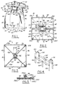
- Fig. 1 illustrates a first embodiment of a bulk-liquid material "squeeze bag” of the invention as the bag would appear fully loaded with liquid bulk material and resting on a flat support and laterally unconfined by a rigid wall enclosure, such as that shown at 300 in Figs. 13 and 14 referred to hereinafter.
- Fig. 1 illustrates a center-lift type hoisting hook 32 chain suspended from an overhead hoist, floor crane, or the like and having its lift arms 34 and 36 respectively hooked under the associated one of a pair of lift straps 38 and 40 formed by the top wall of the bag 30 in accordance with one feature of the invention, and with only light lifting tension being exerted upwardly on bag 30 by hoist attachment 32.
- bag 30 is generally cubical with a generally square horizontal cross section.
- the four vertical sidewalls of bag 30 are defined by a front panel 42, left and right (as viewed in Fig. 1 ), side panels 44 and 46, and rear panel 48.
- the bottom wall of bag 30 is formed by four triangular flaps 50, 52, 54, and 56, respectively, integrally joined at their outer edges respectively to wall panels 42, 44, 46, and 48.
- the flaps are joined at their inner edges to mutually adjacent edges of mutually adjacent flaps by four stitched seams 58, 60, 62, and 64, as shown by the broken hidden lines in Fig. 1 , and by the solid lines in Fig. 3 .
- a rigid-type outlet fitting 66 is mounted centerly of the bottom wall at the junction of the four bottom wall flaps.
- a protective, flexible flap 68 is sewn at 70 to panel 50 and has a hook strip 72, made of hook-and-loop, plastic material such as that sold under the trademark Velcro, sewn to the free end of the underface of flap 68.
- a cooperative loop-type strip 74 is sewn to flap 56 adjacent fitting 66 to cooperate with strip 72 to form a releasable flap protective closure for fitting 66, the same being shown in releasably closed condition at Fig. 12 .
- bag 30 is formed in a manner similar to the manner in which bag 14 of US-A-4,596,040 is constructed, to which further reference may be made, particularly in conjunction with Figs. 2-4 thereof.
- bag 30 of the present invention is likewise formed form a tubular blank 100 of a woven fabric, such as 227 g (8 ounce) coated, high density polyethylene fabric.
- the woven fabric is formed into a tube by sewing the opposite side edges of the fabric together as at 102 (corresponding to seam 12 in Figs. 2 and 3 of US-A-4 596'040).
- the tubular blank 100 when laid flat and with its opposite side folded in, as shown in Fig. 6 , comprises a pair of flat overlying panels which form the opposed front and rear sidewalls 42 and 48 of bag 30 which are connected at their respective side edges by side walls 44 and 46, as folded flat in Fig. 6.
- Side wall 44 forms inwardly folded gussets 44a and 44b, as seen fragmentarily in broken away section of Fig. 6 , which become lefthand sidewall 44 when the bag is expanded.
- inwardly folded gussets 46a and 46b become right-hand sidewall 46 when the bag is expanded.
- each folded gusset 44a, 44b, 46a and 46b has a width which is approximately half the width of the flat front and rear panels 42 and 48 of the bag.
- the fold lines 104 and 106 of gussets 44a, 44b and 46a, 46b extend lengthwise of the bag closely adjacent the longitudinal center line thereof.
- the construction of the longitudinally opposite bottom and top ends of bag 30 differs in several respects from the bag constructed from the bag in US-A-4 596 040 .
- the four flaps 50-56 are formed by simultaneously cutting through the four layers of folded fabric along cut lines 108 and 110 as shown in Fig. 6 and the excess material 112 and 114 of blank 100 is discarded.
- Seam 58 is then stitched to join one edge of flap 50 to the adjacent edge of flap 52, and the remaining flap seams, 60, 62, and 64 are likewise formed by stitching the mutually adjacent pairs of cut edges together.
- a four loop zip tie belt is formed at the bottom apex of bag 30 by turning each of the end points of flaps 50-56 back upon the outside of the flaps and tacking in place to create the four belt loops, the end point belt loop 116 of flap 50 being shown in Fig. 6.
- One large 8 mm (5/16 inch) strip of zip tie material of say 813 mm (32 inches) in length is then threaded through the tunnel created by turning these four points of the bag bottom to the outside of the bag (the zip tie not being shown).
- the bottom end points of the bag bottom flaps of the bag can be constructed as shown in Fig. 12 as described in more detail hereinafter.
- bag 30 while in the folded flat condition of Fig. 6 is formed with four diagonal lines of stitching 120, 122, 124, and 126 which converge centrally at the spout's slit lines which in turn are provided to form the rectangular bag spout 128, similar to spout 42 of the bag shown in Fig. 1 of US-A-4 596'040.
- stitch line 120 joins front panel 42 with left-side fold 44a
- stitch line 122 joins front panel 42 to right-side fold 46a
- stitch line 124 joins rear panel 48 to right-side fold 46b
- stitch line 126 joins rear panel 48 to left-side fold 44b.
- the bag suspension straps 38 and 40 are formed as extended mutual overlaps of the top wall material of the bag.
- the upper folded-in longitudinal extensions 130 and 132 of blank 100 shown in broken lines in Fig. 6 thus are used to quadruple the thickness of the fabric in the shoulder area of the bag. It will be understood that extensions 130 and 132 are laterally spaced apart and formed at their inner edges by the slit lines utilized in making spout 128.
- blank extension 130 used in forming strap 38 consists of the material of front panel 42 connected at a fold at its outer edge to the underlying fold 44a to form a double-ply thickness superimposed over the double-ply thickness, formed by fold 44b connected at its outer folded edge to the back panel 48.
- Each of these four layers of fabric has been severed at its inner edge in making the spout slitting operation.
- the material of blank 100 between extensions 130 and 132 is discarded from where it has been severed from the blank in making the outer edge of spout 128.
- the blank extension 132 used in forming strap 40 is the mirror image of extension 130 and likewise is a four-ply layer of two folds of material with free inner edges.
- the uppermost double-ply layer of extension 130 consisting of the extension portions of front panel 42 and side fold 44a, is folded back in a half loop to bring its free edge against the lowermost double layer of extension 130.
- the free edges of the two uppermost plies are laid against the surface of side fold 44b and secured thereto by a line of stitching 143 ( Fig. 10 ) extending transversely across the four plies near the free edge 139 of this folded over half loop portion.
- blank extension 130 consisting of the side fold 44b and associated extension of rear panel 48, is folded forward in a half loop so that the front surface of fold 44b is laid over and against the outer surface of the extension of panel 42 and joined thereto by a stitch line 134 ( Figs. 6 and 10 ) extending through all four superimposed fabric layers.
- strap 40 is made up of extension portions of back panel 48 and adjacent fold 46b lying over and against the outer surface of panel 42, and its extension, with fold 46a thereunder ( Fig. 11 ), thus likewise forming a four ply thickness strap.
- the free end edges 138 and 140 of straps 38 and 40 are both seen in Figs. 2 and 6 and the rear inner edges 139 and 142 of straps 38 and 40 are all shown in Fig. 2 . It will be seen from the foregoing that the length of blank extension 130 and 132 used in forming the 4-ply straps 38 and 40 can be readily increased or decreased from that shown in accordance with the load requirements of bag 30 to suit differing applications.
- a reinforcement saddle 150 shown by itself in Fig. 4 is stitched to the upper end of bag 30 after forming of the shoulder portions 38 and 40.
- Saddle 150 consists, for example, of 50 mm (two inch) wide orange webbing pieces made up into of four 50 mm (2 inch) wide by 406 mm (16 inch) long vertical support straps 152, 154, 156, and 158 positioned on shoulders 38 and 40 of the front and back panels on either side of spout 128, as shown in Figs. 1, 2, 6, 9, 10 and 11 .
- a central pair of 50 mm (two inch) by 381 mm (15 inch) horizontal support straps 160 and 162 are positioned on front and back panels 42 and 48 152 mm (six inches) below spout 128 and are stitch-connected at their ends to the associated vertical support straps 152-158, as best seen in Fig. 4 .
- a pair of 50 mm (two inch) by 254 mm (10 inch) center support straps 164 and 166 are centered longitudinally on spout 128 and their upper ends stitched respectively to horizonal supports 160 and 162.
- a pair of 50 mm (two inch) by 152 mm (6 inch) canal covers 168 and 170 are positioned so that they are sewn over and connect the tops of the associated pairs of vertical supports 152, 154, 156, and 158, respectively. All of the support members of saddle 150 are connected by multiple lines of stitching to the underlying layers of fabric, the stitching extending through the four ply thickness of shoulders 38 and 40 ( Figs. 9, 10, and 11 ).
- bag 30 is completed by attaching a tubular fill spout 172, preferably made of 142 g (five ounce) weight coated, circular fabric, by telescoping its lower end into spout 128 and securing spout 172 to spout 128 by a line of stitching 174.
- a tie cord 176 preferably made of 12,7 mm (1/2 inch) by 1270 mm (50 inch) polypropylene webbing, is attached at its center to the outer surface of spout extension 172 centrally of the tie cord and at mid length of the spout.
- Another tie cord 178 preferably about 762 mm (30 inch) in length of flat polyethylene tie cord material with acetate tips, is attached by a brass grommet 180 to the upper front edge of bag spout 128.
- the longitudinal stitched side seam 102 of blank 100 is reinforced by sewing on an interior reinforcement patch 182 ( Fig. 6 ), preferably a 152 mm (6 inch) by 406 mm (16 inch) 228 g (8 ounce) fabric of the same material as blank 100, and positioned with its lower edge about 50 mm (two inches) above the bottom corner end of seam 102 so as to overlap the inside surfaces of the sewn edge of the front and side panels 42 and 44.
- Bag 30 is provided with a liquid impermeable, form-fitting interior liner, generally designated as 200 in Fig. 7 , wherein liner 200 is shown by itself in folded flat condition.
- Liner 200 is constructed similar to liner 92 described in conjunction with Fig. 18 of US-A-4,596,040.
- liner 200 is constructed of four millimeter thickness, ultraviolet resistant, low density polyethylene of two ply thickness, to provide a high strength liquid impermeable interior lining for bag 30, and in the embodiment of Figs. 1-16 which is preferably permanently attached to the interior of bag 30.
- the upper end of liner 200 is formed with a tubular spout 202 which when opened is square and concentric with bag spout 128, as best seen in Fig. 2.
- the liner blank is preferably longer than the bag blank so that, when the liner is inserted into the bag, spout 202 of the liner will extend outwardly beyond the spout extension 172 of the bag.
- Bag liner 200 is formed from an initially seamless tubular blank extrusion and, after being in-folded and laid flat, is cut, as shown in Fig. 7 , at its axially opposite ends to form the four end flaps at each end. These flaps are heat sealed together along their mating edges and have the inclined shape and inwardly folded side wall gusset panels corresponding to the ends of bag 30. The blank of liner 200 when folded flat as shown in Fig.
- the liner 7 preferably slightly narrower in width than that of the bag blank so that the liner will fit in the bag in a flattened condition with its gusset panels interleaved with the gusset panels of the bag, but not necessarily.
- the liner is preferably the same size circumferentially or even 25,4 mm (an inch) or so longer on each side so that no stress will be on the film and almost all stress will be contained by the stronger outer fabric bag.
- Spout 66 preferably is a 85,7 mm (3 3/8 inch) L.B. transport flange type C positioned at the bottom point of liner 200.
- Spout 66 thus has an annular external flange 204 at its upper end and another external flange 206 spaced there below. These two flanges define an external groove for receiving the free end edges of the bottom flaps of both liner 200 and bag 30 which are tucked into this groove in the manner shown in Fig. 12 . If bag 30 has the folded back end flaps belt loops 116 shown in Fig.
- the tucked-in flap free ends may be secured with the aforementioned tie cord strung through the belt loops.
- the bag and liner flap free ends may be made to be tucked into the groove between flanges 204 and 206 and hermetically secured therein by an encircling retaining band 208.
- Band 208 may be a commercially available heavy duty plastic cable-tie.
- the plastic material of liner 200 is further attached and hermetically sealed to the underside of flange 204 by a annular sonic weld seam 210.
- the neck 212 of spout 66 is internally threaded to receive a plastic screw cap 214 removably threaded thereinto and sealed by an O-ring 216. Flap 68 when removably fastened by the hook and loops 72, 74 spans beneath spout 66 and cap 214 to provide a protective cushioned barrier for the same.
- Liner 200 may be installed in bag 30 following the procedure set forth with reference Figs. 19-21 of US-A-4,596,040, and if desired employing the installation tool 116 described in US-A-4 596 040. After so installing liner 200 in bag 30 with both of them in their flattened, folded condition shown respectively in Figs. 6 and 7 , liner 200 becomes completely interleaved with the flattened bag. With the liner so arranged in the bag, when the bag is filled the liner will automatically expand into cubicle shape simultaneously with expansion of the bag.
- liner 200 is secured in bag 30 by provision eight tape-tabs 220-236 (see Figs. 1-3 as well as Figs. 7 and 8 ).
- the upper tape-tabs 220, 224, 230, and 232 are positioned on all four top shoulders about one inch up from the corner shoulder, and the bottom tape-tabs 226, 228, 234, and 236 are likewise positioned individually on all four bottom shoulders about one inch down from the corner of the shoulder.
- the tape-tabs may be constructed in accordance with those disclosed in US-A-4,781,472.
- each tape tab 220-236 is made from fiber reinforced filament adhesive tape formed into a U-shaped loop having overlapped runs 226a and 226b and end portions 226c and 226d ( Fig. 8 ) adhesively secured to the respective shoulder edge seam of liner 200.
- a reinforcing piece may be inserted and secured between runs 226a and 226b, if desired (not shown).
- Bag 30 when being sewn at the end panel seams 120-126 and 58-64 is left with an unstitched gap, slightly wider than tab rum 226a, 226b, at each of the eight tab locations in the bag.
- bag 30 With liner 200 installed therein is best seen in Figs. 1 and 13-16 .
- the bag 30/liner 200 is best fined into an open ended rigid encircling rigid retainer, such as the hexagonal retainer 300 shown in Figs. 13 and 14 .
- Such retainers may be made square, hexagonal, or octagonal from corrugated box material, rigid plastic board material, wire cages, metal bins, or rectangular knock-down plywood panels, as is well understood in the art.
- Such containers may be supported at their bottom edge on a flat pallet 302 as shown in Fig. 13 , and the entire assembly secured by strapping bands 304-310 encircling the entire assembly as shown in Fig. 13 .
- Retainer 300 may also have a removable flanged top 312 if desired, with suitable opening tabs 314 to permit access to the upper spouts 128 and 202 of the bag and liner, respectively. Due to the flexible nature of bag 30 and liner 200, the same will form-fit to any such shape of container 300 either by the pressure of the contents in the bag/liner, or, when the bag is empty, by suitably inflating the bag with a forced air blower such as a shop vacuum/blower appliance. However leaf-blower type driven appliance is preferred for this purpose.
- the hoist attachment 32 When it is desired to empty the bag of its contents, the hoist attachment 32 is attached to bag 30 by inserting its arms 34 and 36 under the bag shoulders 38 and 40 respectively when the same are in relaxed condition. Then attachment 32 is raised to put light tension on shoulder straps 38 and 40, as shown in Fig. 1 . The bag may then be hoisted out of container 300 as shown in Fig. 14 . When the bag has been properly positioned by hoist 32, as by being suspended over a suitable receiver for the contents of the bag, protection flap 68 may be unhooked from its protective position shown in Fig. 12 to its detached position shown in Fig. 6 to thereby properly expose the discharge end of spout 66 for use.
- the quadruple ply construction of straps 38 and 40 and this suspension from hoist arms 34 and 36 also assists in maintaining the upper reaches of front and rear walls 42 and 48 generally planar in form so that the opposed center-fold-creased sidewalls 44 and 46 yield and fold inwardly under the pressure of the front and back panels as the bag contents are discharged from spout 66.
- the construction of both bag 30 and liner 200 initially in folded form with this folded-in gusset panels also tends to cause the bag to return to its original folded, flat condition as it is emptied.
- squeeze bag 30 can be additionally squeezed by use of externally applied squeeze rollers which are engaged initially at the top of the bag to nip together front and rear panels 42 and 48 near hoist 32. The squeeze rollers are then forced together while being rolled down the bag to thereby wring out the remaining contents of bag 30 by this externally applied roller ringer action.
- This mode of bag wring out and one suitable squeeze roller tool 320 for such use is illustrated in Figs. 15 and 16 .
- Tool 320 preferably consists of a pair of rollers 322 and 324 having a lengthwise dimension greater than the width of the front and rear panels 42 and 48. Rollers 322 and 324 are held with their rotational axes parallel and laterally spaced from one another by an articulating linkage best seen in Fig. 15 .
- This linkage includes a pair of crossed links 326 and 328 pivotally interconnected by a pivot 330 at their midpoint.
- the lower end of link 328 rotatably carries one end of roller 322, and the lower end of link 326 rotatably carries the adjacent end of roller 324.
- a hook 331 and associated latch 332 at the lower end of link 326 allow the associated end of roller 324 to be released from engagement with the link.
- Another pair of crossed, pivotally interconnected links 334 and 336 are provided to rotatably support the opposite ends of rollers 324 and 326. The rollers thus may be spread apart and forced together by suitably manually operating the articulating leverage of this linkage.
- An operating handle 340, 342, 344 and 346 is rigidly affixed at its free end one to each of the associated links 326, 328, 334 and 336 respectively so as to protrude in a plane perpendicular to and spaced from pivot axis of the linkage. Grip handles are provided at the ends of these handles to facilitate manual operation of the linkage.
- the tool is easily opened by unlatching link 326 from the associated end of roller 324.
- This allows tool 320 to be inserted from one side of bag 30 while suspended on the hoist, the tool being spread open to span across the upper reaches of the front and rear panels of the bag, as shown in Fig. 15 .
- the loose end of roller 324 is re-hooked to link 326 and latch 332 closed.
- Two operating persons stationed at one at each of the opposite sides of the bag then grip the linkage handles and pull downwardly on the same.
- tool 320 can be readily modified for use in an inverted relationship from that shown and described in Figs. 15 and 16 , i.e., with nip roller 324 and 326 positioned above the articulating linkage.
- handles 340-346 are re-oriented relative to their associated links 326, 328, 334, 336 so as to extend therefrom axially opposite from that shown in Figs. 15 and 16 .
- manual pull force exerted on each set of the handles will develop both the aforementioned nip forces to squeeze the rollers together as well as to pull the rollers down along the length of the bag.
- Such handle orientation reversal can facilitate bag squeezing operation when bag 30 is suspended at higher elevations relative to the operating personnel.
- the length of the links between their pivot points and the operating handles can be varied to change the mechanical advantage of the linkage, if desired, as well as to vary the vertical reach of the tool rollers.
- Figs. 17-20 illustrate a second embodiment of a bulk liquid squeeze bag 250 also constructed in accordance with the present invention, in which elements previously described are given the same reference numerals and their description not repeated.
- Bag 250 is similar to bag 30 but differs therefrom in respect to the shoulder reinforcement and lower end closure features of the bag. Also, bag 250 is adapted to removably receive a liquid-type bag liner identical to liner 200 except for the manner of interconnection of the tape-tabs 220-236 to bag 250.
- Liner 200 for bag 250 may be rendered removable from the bag by providing liner 200 with tape-tabs of the type disclosed in conjunction with Figs. 1-5 of US-A-4,781,472.
- the liner tabs may have grommets in the portions of the tabs protruding from their attachment to the liner for attaching a suitable tie cord or spring clip loop.
- liner 200 has only two tie tabs are these are attached to its front and back panels spaced a short distance above their apices (not shown).
- bag 250 is provided with attachment holes for receiving the tie cord or clip of each of the tape tabs.
- a pair of such bag tie holes 252 and 254 are formed in upper shoulder seams 120 and 122 spaced about one inch above the junction of these shoulders with the associated side edges of the bag.
- similar tie holes 256 and 258 are provided in upper shoulder seams 122 and 124 of bag 250. These holes may be formed by burning through the plastic fabric construction of bag 250 while laid flat and the sides folded inwardly.
- tie holes 260 and 262 are provided in the lower front flap panel of the bag spaced suitably above its apex.
- a similar pair of burn-through holes are located directly opposite holes 260 and 262 in the lower rear flap panel of bag 250.
- Four tie cords or clips are attached one to each of the four upper tie tabs of the liner and two are likewise attached to the two tie tabs at the lower end of the liner.
- the six cords or clips are passed through the bag holes to tie off the liner tabs to the bag to thereby removably attach the liner in the bag.
- Girdle 270 comprises a suitable length, e.g., 1143 mm (45 inches) of 50 mm (two inch) wide woven plastic strapping to form a belt 272 with four extension straps 274, 276, 278 and 280 overlaid at their upper ends on belt 272 and stitched thereto with their upper edges flush with the upper edges of belt 272. Straps 274-280 are spaced equally apart and extend lengthwise perpendicularly to belt 272 as shown in Fig.
- trapezoidally shaped fabric reinforcement gusset "petals" 282, 284, 286 and 288 are stitched along their base edge to the side of belt 272 opposite from that to which straps 274-280 are attached, and are individually centered on the associated strap and also stitched thereto.
- reinforcement girdle 270 is positioned at the lower end of the bag so that belt 272 completely encircles all four of the bottom shoulder panels 50, 52, 54 and 56 of the bag at the junction therewith of four end flaps 50a, 52a, 54a and 56a which are formed as integral individual extensions of these panels.
- Such bottom panel flaps 50a-56a are formed by terminating the shoulder seams 58, 60, 62 and 64 short of the lower end of the bag shoulder panels so that their lower ends are left unjoined to form these flaps.
- Petals 282-288 individually register with associated bottom panel flap, and the lower edges of the petals and lower edges of the flaps are stitched thereto as shown in Figs. 19 and 20 .
- Each of the straps 274-280 is folded inwardly and back upwardly as to return loop to lay against the inner face of the associated panel flap as shown in Fig. 19 .
- the juxtaposed layers of strap 276, petal 284, bag flap 50a and the return loop 276a are stitched together as shown in Fig. 19 .
- a polypropylene webbing tie cord 292 of say 12,7 mm (one-half inch) width and 1016 mm (40 inch) length, is then strung through these belt loops as shown in Figs. 17, 19 and 20 .
- a discharge chute 290 is secured internally to the bag bottom panels at its upper end by stitching, and is made of circular coated fabric of a suitable length to hang downwardly from the bottom of the bag as shown in Fig. 17 .
- a protective flap 294 may be stitched at its upper edge to the inner face of the folded back strap extension 276a, as shown in Fig. 19 , so as to hang therefrom adjacent discharge chute 290 in the spout-opened condition of bag 250.
- Spout 290 is also provided with its own webbing tie cord 296 ( Fig.
- bag 250 for tying the spout closed when it is to be tucked back inside the opened panel flaps 50a-56a when closing lower end opening of bag 250.
- the bottom of bag 250 may then be very securely held closed by drawing tight and tieing off cord 292 thereby drawing the belt petals 282-288 together to form a secure, rugged yet flexible closure array across the bottom end of the bag.
- lift straps 38 and 40 may be reinforced by a pair of reinforcement panels 298 and 300 positioned as shown in Fig. 17 so as to lay against and be stitched to facing surfaces of bag side panel folds 44a, 44b, and 46a, 46b respectively.
- the upper ends of the U-shaped reinforcement panels 298 and 300 are slit in the bag spout 128 forming operation so that the inner ends of hook aims 34 and 36 of hoist 32 can form catches with the straps 38 and 40 in the manner of the construction of bag 30 and its attachment to hoist 32 as shown in Fig. 1 .
- the modified bag 250 of the invention thus is well adapted for use as a bulk liquid content squeeze bag in the manner previously described in conjunction with bag 30 with reference to Figs. 13-16 , as well as Fig. 1 .
- bag 250 is particularly well-suited for use with a removable liner containing very thick viscous materials and having its own discharge spout which can be reliably sealed with a tie cord, as further secured by using tie cord 296 to tie off bag discharge spout 290, but which materials also require flexible bag and liner discharge spouts, each having a large cross-sectional flow area, that can be squeezed flat together during the final emptying operation of the bag.
- the liner (not shown) employed in bag 250 is preferably modified from the construction of liner 200 so as to provide a downspout at its lower end identical to the fill spout 202 of liner 200, instead of having the rigid plastic outlet fitting 66.
- This liner discharge spout thus telescopes downwardly and outwardly within the bag outlet spout 290 in much the same manner as the fill spout 202 extends out within upper spout 172 of bag 30.
- the squeeze roller tool 320 can be employed as described previously to squeeze out all of the bag contents or any contents remaining in the bag after gravity discharge thereof. Due to the flexible nature of the lower end closure construction of bag 250, these nip rollers can be run completely down the length of the bag and over the discharge spout to thereby squeeze even the last remaining contents out of the bag and hence out of the discharge spout.
- the bag liner In the case of very sticky materials, or materials subject to spoilage such as food materials, the bag liner would be intended only for one-time use. Hence the removable attachment of the liner as provided in the construction of bag 250 will enable the liner to be readily removed from the bag after the bag has been emptied and squeezed flat. Preferably this is accomplished with the bag hoisted and suspended on hoist 32. The upper shoulder ties are untied after the lower ones are untied, and then the bag liner is stripped from the bag by pulling the same downwardly and out of the bag discharge spout.
- either of the first and second embodiment bags 30 and 250 can be constructed as a multi-lift style bag by the addition of four corner hoisting straps 302, 304, 306 and 308 by following the corner strap construction disclosed in US-A-4,781,473; 5, 104,236 and/or 5,358,335, Due to the flexibility of the four corner straps 302-308, the same do not impede the roller wringer squeeze action when use of squeeze roller tool 320 is desired.
Landscapes
- Engineering & Computer Science (AREA)
- Mechanical Engineering (AREA)
- Bag Frames (AREA)
- Containers And Packaging Bodies Having A Special Means To Remove Contents (AREA)
Claims (13)
- Grand sac flexible et comprimable destiné à un usage en position verticale qui présente les caractéristiques suivantes :une paroi latérale, des extrémités supérieure et inférieure et des ouvertures aux extrémités supérieure et inférieure (128, 66) vers l'extérieur du sac (30, 250) qui permettent respectivement de remplir et de vider le sac;une doublure flexible et comprimable (200) contenue dans le sac (30, 250) et complémentaire dans l'ensemble à celui-ci et possédant une paroi latérale, des extrémités supérieure et inférieure et des ouvertures aux extrémités supérieure (202) et inférieure qui permettent respectivement de remplir et de vider le sac;le sac (30, 250) comprend une ébauche tubulaire (100) en matériau tissé flexible renforcé;l'ébauche (100) possède une portion centrale continue sur son pourtour et quatre portions en forme de triangle isocèle (50, 52, 54, 56) adjacentes à chaque extrémité qui sont réalisées et disposées de sorte que le sac déplié présente une forme générale cubique avec deux parois latérales de forme générale rectangulaire (42, 48) reliées par deux parois repliables (44, 46), et lorsque le sac (30, 250) est vide il peut être comprimé et plié selon une forme générale plate;chacune des trois portions triangulaires (50, 52, 54, 56) s'étend de la partie centrale de l'ébauche vers le sommet de la portion triangulaire,des moyens de liaison (58, 60, 62, 64, 120, 122, 124, 126) relient entre elles les portions triangulaires adjacentes le long de leurs bords selon des lignes de liaison qui s'étendent au moins depuis le voisinage immédiat de la portion centrale jusqu'à au moins midistance des sommets correspondants, et les lignes de liaison associées aux portions triangulaires (50, 52, 54, 56) adjacentes à l'extrémité associée de la portion centrale se terminent au voisinage immédiat de leurs sommets,
de sorte à déterminer au moins en partie une ouverture d'accès (au niveau de 116, 128), et ce au voisinage du centre de l'extrémité correspondante qui est déterminée par ces portions triangulaires lorsque le sac est déplié, de sorte que, lorsque le sac est rempli, il présente deux extrémités distantes et de forme générale conique qui sont reliées entre elles par quatre parois latérales de forme générale rectangulaire, de sorte que les extrémités se rejoignent en se rétrécissant au niveau de l'ouverture d'accès correspondante (au niveau de 116, 128), et de sorte que les portions triangulaires de l'extrémité du sac peuvent être repliées, lorsque le sac (30, 250) est vide, sous forme compacte qui présente deux parois antérieure et postérieure superposées (42, 48) et deux parois repliées (44, 46) entre elles, de sorte que le pli entre les parois adjacentes pliées s'étende pour l'essentiel entre les sommets des portions triangulaires opposées correspondantes et que les plis sont immédiatement voisins les uns des autres;des première et seconde sangles de suspension (38, 40) en forme de U espacées latéralement formées à la partie supérieure du sac (30, 250) et qui encadrent ensemble les ouvertures supérieures (128) du sac et de la doublure, caractérisé par le fait quela sangle de suspension (38, 40) présente une première extension (130) à deux couches constituée d'une partie de la portion triangulaire de la paroi antérieure (42) et d'une partie (44a, 46a) de la portion triangulaire de la paroi latérale qui lui est reliée, et qui s'étend vers le haut jusque au-delà de l'ouverture d'accès supérieure (128) du sac à partir des moyens de liaison (120, 122, 124, 126) qui relient entre elles les portions triangulaires (42, 44a, 46a) des parois antérieure et latérale et se terminent sur un bord terminal libre (139, 142),une seconde extension à deux couches (132) est constituée d'une partie de la portion triangulaire de la paroi postérieure (48) et d'une partie (44b, 46b) de la portion triangulaire de la paroi latérale qui lui est reliée, et s'étend également vers le haut jusque au-delà de l'ouverture d'accès supérieure (128) du sac à partir des moyens de liaison (120, 122, 124, 126) qui relient entre elles les portions triangulaires (48, 44b, 46b) des parois postérieure et latérale et se terminent sur un bord terminal libre (138, 140);les première et seconde extensions à deux couches (130, 132) présentent des portions qui se recouvrent mutuellement et sont reliées de manière permanente entre elles (134, 143) pour constituer ainsi une boucle de suspension en forme de U d'une épaisseur de quatre couches où les extensions (130, 132) se recouvrent mutuellement etles sommets des sangles (38, 40) sont alignés de manière coaxiale et à une certaine distance respective au-delà des ouvertures d'accès supérieures (128) du sac et de la doublure quand elles sont fermées. - Sac selon la revendication 1 caractérisé par le fait quechaque couche de tissu des sangles de suspension correspondantes (38,40) présente un bord intérieur libre adjacent au côté correspondant du sac et quel'ouverture d'accès de la doublure (128) est constituée par une fente à la partie supérieure de l'ébauche (100) au travers des première et seconde extensions à deux couches (130, 132) de la sangle de suspension correspondante (38, 40) lorsque l'ébauche (100) est pliée à plat.
- Sac selon la revendication 2 caractérisé par le fait quele sac présente un renforcement par sangles en forme de selle (150) qui comprend des première et seconde sangles terminales en forme de U (168, 170) qui sont disposées sur les première et seconde sangles de suspension (38, 40) le long de leurs bords intérieurs libres et s'étendent vers les extrémités libres placées en vis à vis longitudinal qui se trouvent dans les parois antérieure et postérieure du sac (42, 48) sous les moyens de liaison (120, 122, 124, 126),des première et seconde sangles transversales (160, 162) s'étendent entre les sangles terminales en forme de U (168, 170) et sont reliées à ces sangles terminales par leurs extrémités opposées tout en étant disposées au voisinage et en dessous de l'ouverture d'accès supérieure (128),des première et seconde sangles centrales (164, 166) sont reliées par leurs extrémités supérieures respectives aux première et seconde sangles transversales (160, 162) et s'étendent de celles-ci vers le bas sur les parois antérieure et postérieure (42, 48),toutes les sangles du renforcement en forme de selle (150) sont fixées de manière permanente aux surfaces adjacentes respectives du sac au niveau des zones de contact des sangles.
- Sac selon la revendication 3 caractérisé parune goulotte de remplissage tubulaire (172) au pourtour continu et constituée d'un tronçon coupé dans un matériau flexible;le fait que la goulotte (172) est disposée dans l'ouverture d'accès supérieure centrale (128) de sorte qu'une zone terminale de chaque portion triangulaire constitue cette ouverture d'accès centrale et recouvre la goulotte (172);des moyens de liaison (174) qui relient la goulotte tubulaire (172) à la portion triangulaire au moins pour l'essentiel autour du bord de la goulotte et de sorte que la goulotte de remplissage (172) peut être étirée entre et au delà des sangles de suspension (38, 40).
- Sac selon les revendications 1 à 4 caractérisé parune goulotte d'écoulement (66) qui définit au moins en partie l'ouverture d'écoulement du sac (30) et le fait que la doublure (200) présente une goulotte d'écoulement (66) qui définit au moins en partie l'ouverture d'écoulement de la doublure et qui peut être étirée dans la goulotte d'écoulement du sac.
- Sac selon la revendication 5 caractérisé par le fait queà l'extrémité inférieure de l'ébauche (100), chaque ligne de liaison (58,60,62,64) des côtés adjacents des portions triangulaires adjacentes (50, 52, 54, 56) s'étend pour l'essentiel jusqu'à leur sommet, mais s'arrête toutefois peu avant ce sommet pour constituer une extrémité ouverte dans le fond du sac et libérer au niveau du sommet triangulaire quatre pattes (50a, 52a, 54a, 56a) qui s'étendent vers le bas, à raison d'une par portion triangulaire,le sac comprend en outre une ceinture de renfort (270) qui comprend une sangle horizontale (272) qui entoure les portions triangulaires et est fixée sur celles-ci à la jonction des lignes de liaison avec les pattes pointues,la ceinture (270) comprend quatre boucles de sangle (274, 276, 278, 280) qui sont reliées par une extrémité à la sangle horizontale (272), sont centrées par rapport à la patte correspondante (50a, 52a, 54a, 56a) et s'étendent vers le bas jusque au-delà de l'extrémité inférieure de la patte, puis vers le haut le long de la face intérieure de la pattejusqu'à une liaison à l'autre extrémité avec la patte et la sangle horizontale, de sorte que chaque sangle forme à son extrémité inférieure une boucle dont le sommet se trouve sous le bord inférieur de la patte correspondante etun lacet est enfilé successivement dans les boucles sous les bords inférieurs des pattes de sorte à tirer les uns contre les autres les bords inférieurs des boucles de sangle lorsqu'il est serré afin de tirer les unes contre les autres les pattes correspondantes (50a, 52a, 54a, 56a) sur l'ouverture d'écoulement inférieure du sac.
- Sac selon la revendication 6 caractérisé par le fait quela ceinture (270) présente une surface de renforcement de forme générale triangulaire (282 à 288) pour chacune des sangles (274 à 280),chaque surface de renforcement a sa base fixée à la sangle horizontale (272) et son sommet centré sur la boucle de sangle correspondante (274 à 280) de manière à former un angle de renfort pour la sangle, à recouvrir la patte de fermeture correspondante du sac et à être liée de manière permanente à celle-ci.
- Sac selon la revendication 7 caractérisé parun volet (290) en matériau flexible constitué et disposé de sorte à recouvrir et à pouvoir découvrir l'ouverture inférieure centrale du sac dans laquelle est disposée la goulotte d'écoulement et qui recouvre au moins partiellement au moins une partie d'au moins une des portions triangulaires au fond du sac sur sa face intérieure, de sorte qu'un moyen de liaison relie le volet d'obturation flexible (290) à l'une des portions triangulaires de sorte que le volet d'obturation recouvre les pattes triangulaires à l'intérieur lorsque la ceinture (270) est serrée avec le lacet (292).
- Sac selon la revendication 8 caractérisé par le fait quela doublure (200) possède deux parois latérales de forme générale rectangulaire et deux parois de liaison pliables dont les formes sont complémentaires de celles des parois correspondantes du sac,la doublure est réalisée et disposée de sorte à présenter une forme générale cubique lorsqu'elle est dépliée et à être pliée selon une forme générale plate lorsqu'elle est vide;plusieurs moyens de liaison (220 à 236) sont prévus entre la doublure (200) et le sac (30, 250) de sorte que chaque moyen de liaison relie la doublure (200) au sac (30, 250);les moyens de liaison (220 à 236) sont disposés espacés les uns des autres et au voisinage de la partie de paroi latérale du sac ainsi qu'au voisinage du fond du sac de sorte que la doublure présente des ouvertures d'écoulement au travers;tous les moyens de liaison (220 à 236) sont reliés à la doublure (200) de sorte que la doublure ne puisse pas être tirée hors du sac (30, 250) et puisse s'affaisser sur elle-même pendant l'écoulement du contenu, et ce indépendamment de l'affaissement du sac et sans être gênée pour l'essentiel par le sac, alors que le contenu du sac et de la doublure s'écoule par les ouvertures d'écoulement sans que la doublure (200) ne soit arrachée du fond du sac par cet écoulement etle sac, la doublure ainsi que les goulottes de remplissage et d'écoulement (290) de même que la ceinture (270) sont tous fabriqués en matériau flexible et peuvent être pressés les uns contre les autres en tirant deux rouleaux pinceurs (320) sur la totalité de la longueur du sac et des goulottes alors que le sac est suspendu par les sangles de suspension.
- Sac selon la revendication 9 caractérisé par le fait quechaque moyen de liaison (220 à 236) comprend respectivement un collier qui est fixé à la doublure (200) par une première partie et présente une seconde partie qui s'en écarte par une ligne de liaison entre une paire adjacente des portions triangulaires et est reliée à celles-ci par formation d'une jointure qui forme la ligne de liaison.
- Sac selon la revendication 4 caractérisé par le fait quela doublure (200) présente une goulotte d'écoulement rigide (66) de sorte qu'une bride annulaire externe (204) est reliée de manière étanche aux liquides au matériau de la doublure et constitue la partie inférieure de la doublure,la goulotte (66) présente une extrémité d'écoulement (212) qui fait saillie vers le bas au travers de l'ouverture d'écoulement du sac et comprend un bouchon amovible (214) sur la partie inférieure de la goulotte (66),le sac comprend un capuchon extérieur (68) qui est fixé de manière permanente par une extrémité sur l'une des portions triangulaires au fond du sac et s'étend au dessous et en travers du bouchon de goulotte, tout en présentant une extrémité libre qui est fixée de manière détachable par crochet et oeillet ou par bande agrippante (72, 74) à respectivement une autre portion triangulaire du sac de sorte que le capuchon recouvre le bouchon par le bas afin de servir de protection détachable et flexible à la goulotte.
- Procédé pour soutirer un matériau collant et visqueux d'un grand sac flexible et comprimable, comprenant les étapes suivantes :a) on dispose d'un grand sac flexible et comprimable (250, 30) qui comprend une paroi latérale, des extrémités supérieure et inférieure ainsi que des ouvertures aux extrémités supérieure et inférieure (128, 66) vers l'extérieur du sac (30, 250) qui permettent respectivement de remplir et de vider le sac;une doublure flexible et comprimable (200) est contenue dans le sac et complémentaire dans l'ensemble à celui-ci et possède une paroi latérale, des extrémités supérieure et inférieure et des ouvertures aux extrémités supérieure (202) et inférieure qui permettent respectivement de remplir et de vider le sac;le sac (30, 250) comprend une ébauche tubulaire (100) en matériau tissé flexible renforcé; l'ébauche (100) possède une portion centrale continue sur son pourtour et quatre portions en forme de triangle isocèle (50, 52, 54, 56) adjacentes à chaque extrémité qui sont réalisées et disposées de sorte que le sac déplié présente une forme générale cubique avec deux parois latérales de forme générale rectangulaire (42, 48) reliées par deux parois repliables (44, 46), et lorsque le sac est vide il peut être comprimé et plié selon une forme générale plate, de sorte que chacune des trois portions triangulaires s'étend de la partie centrale de l'ébauche vers le sommet de la portion triangulaire;des moyens de liaison (58, 60, 62, 64, 120, 122, 124, 126) relient entre elles les portions triangulaires adjacentes (50, 52, 54, 56) le long de leurs bords selon des lignes de liaison qui s'étendent au moins depuis le voisinage immédiat de la portion centralejusqu'à au moins midistance des sommets correspondants; les lignes de liaison associées aux portions triangulaires (50, 52, 54, 56) adjacentes à l'extrémité associée de la portion centrale se terminent au voisinage immédiat de leurs sommets, de sorte à déterminer au moins en partie une ouverture d'accès (au niveau de 116, 128), et ce au voisinage du centre de l'extrémité correspondante qui est déterminée par ces portions triangulaires lorsque le sac est déplié, de sorte que, lorsque le sac est rempli, il présente deux extrémités distantes et de forme générale conique qui sont reliées entre elles par quatre parois latérales de forme générale rectangulaire, de sorte que les extrémités se rejoignent en se rétrécissant au niveau de l'ouverture d'accès correspondante (au niveau de 116, 128), et de sorte que les portions triangulaires de l'extrémité du sac peuvent être repliées, lorsque le sac est vide, sous forme compacte qui présente deux parois antérieure et postérieure superposées (42, 48) et deux parois repliées (44, 46) entre elles, de sorte que le pli entre les parois adjacentes pliées s'étende pour l'essentiel entre les sommets des portions triangulaires opposées correspondantes et que les plis sont immédiatement voisins les uns des autres;le sac (30, 250) comprend par ailleurs des première et seconde sangles de suspension (38,40) en forme de U espacées latéralement formées à la partie supérieure du sac et qui encadrent ensemble les ouvertures supérieures (128) du sac et de la doublure;chaque sangle de suspension (38, 40) présente une première extension (130) à deux couches constituée d'une partie de la portion triangulaire de la paroi antérieure (42) et d'une partie (44a, 46a) de la portion triangulaire de la paroi latérale qui lui est reliée, et qui s'étend vers le haut jusque au-delà de l'ouverture d'accès supérieure (128) du sac à partir des moyens de liaison (120, 122, 124, 126) qui relient entre elles les portions triangulaires (42, 44a, 46a) des parois antérieure et latérale et se terminent sur un bord terminal libre (139, 142), une seconde extension à deux couches (132) est constituée d'une partie de la portion triangulaire de la paroi postérieure (48) et d'une partie (44b, 46b) de la portion triangulaire de la paroi latérale qui lui est reliée, et s'étend également vers le haut jusque au-delà de l'ouverture d'accès supérieure (128) du sac à partir des moyens de liaison (120, 122, 124, 126) qui relient entre elles les portions triangulaires (48, 44b, 46b) des parois postérieure et latérale et se terminent sur un bord terminal libre (138, 140);les première et seconde extensions à deux couches (130, 132) présentent des portions qui se recouvrent mutuellement et sont reliées de manière permanente entre elles (134, 143) pour constituer ainsi une boucle de suspension en forme de U d'une épaisseur de quatre couches où les extensions (130, 132) se recouvrent mutuellement, alors que les sommets des sangles (38, 40) sont alignés de manière coaxiale et à une certaine distance respective au-delà des ouvertures d'accès supérieures (128) du sac et de la doublure quand elles sont fermées;b) le sac (30, 250) et la doublure (200) sont suspendus verticalement après avoir été levés avec un dispositif de suspension (32) qui possède deux bras de levage espacés coaxialement (34, 36) et respectivement insérés dans les boucles des sangles de suspension (38, 40);c) deux rouleaux pinceurs (322, 324) sont mis en place respectivement en travers des parois antérieure et postérieure (42, 48) du sac (30, 250), en commençant au voisinage de l'extrémité supérieure du sac alors que celui-ci est suspendu;d) une pression de serrage est appliquée de manière à presser les rouleaux pinceurs (322, 324) l'un contre l'autre en relation de compression avec le sac (30, 250) de sorte à presser les parois antérieure et postérieure (42, 48) l'une contre l'autre pendant que les rouleaux pinceurs (322, 324) sont tirés vers le bas le long des parois antérieure et postérieure (42, 48) pour repousser le contenu restant dans le sac vers le bas devant la pression des rouleaux et exprimer le contenu par l'ouverture d'accès de la doublure et du sac.
- Procédé selon la revendication 12 dans lequel à l'étape a), le sac (30, 250) est constitué et disposé de sorte que les ouvertures d'écoulement de la doublure (200) et du sac (30, 250) sont fabriquées en matériau flexible et comprimable et dans lequel, à l'étape d), les rouleaux pinceurs (322, 324) sont tirés vers le bas sur la course d'un rouleau pinceur qui se prolonge le long du matériau des ouvertures d'écoulement du sac et de la doublure jusqu'à ce que le contenu restant soit exprimé de la doublure et du sac par l'action des rouleaux pinceurs.
Applications Claiming Priority (2)
| Application Number | Priority Date | Filing Date | Title |
|---|---|---|---|
| US705419 | 1996-08-29 | ||
| US08/705,419 US5690253A (en) | 1996-08-29 | 1996-08-29 | Large bulk liquid squeeze bag |
Publications (2)
| Publication Number | Publication Date |
|---|---|
| EP0826609A1 EP0826609A1 (fr) | 1998-03-04 |
| EP0826609B1 true EP0826609B1 (fr) | 2000-01-12 |
Family
ID=24833378
Family Applications (1)
| Application Number | Title | Priority Date | Filing Date |
|---|---|---|---|
| EP97114474A Expired - Lifetime EP0826609B1 (fr) | 1996-08-29 | 1997-08-21 | Grand sac comprimable pour produits visqueux |
Country Status (5)
| Country | Link |
|---|---|
| US (1) | US5690253A (fr) |
| EP (1) | EP0826609B1 (fr) |
| CA (1) | CA2201548C (fr) |
| DE (1) | DE69701115D1 (fr) |
| MX (1) | MX9703136A (fr) |
Families Citing this family (33)
| Publication number | Priority date | Publication date | Assignee | Title |
|---|---|---|---|---|
| AU766785B2 (en) | 1998-06-09 | 2003-10-23 | Lance John Muller | Liner bag for flexible bulk container |
| US6200300B1 (en) | 1998-11-18 | 2001-03-13 | David S. Smith Packaging Limited | Hangable container |
| USD438454S1 (en) | 1998-11-20 | 2001-03-06 | Lance John Muller | Bag |
| US6296150B1 (en) | 1999-02-25 | 2001-10-02 | Barry Farris | Medicinal dosing apparatus and method |
| US20030017066A1 (en) * | 2001-07-19 | 2003-01-23 | Baxter International Inc. | Apparatus, flexible bag and method for dispensing |
| US6905314B2 (en) * | 2001-10-16 | 2005-06-14 | Baxter International Inc. | Pump having flexible liner and compounding apparatus having such a pump |
| US20060280390A1 (en) * | 2002-06-20 | 2006-12-14 | Richardson Joe R Jr | Bulk bag liners for receiving, transporting, and discharging meat and meat products |
| US7007824B2 (en) | 2003-01-24 | 2006-03-07 | Baxter International Inc. | Liquid dispenser and flexible bag therefor |
| FR2851242B1 (fr) * | 2003-02-13 | 2005-10-21 | Rhodia Chimie Sa | Procede de vidange d'un conteneur souple renfermant un produit visqueux |
| US20050025393A1 (en) * | 2003-07-29 | 2005-02-03 | Aaron Heyniger | Bag apparatus |
| US7269875B1 (en) * | 2003-11-19 | 2007-09-18 | David Brian Grimes | Cleaning apparatus |
| CA2452291A1 (fr) * | 2003-12-31 | 2005-06-30 | Soheyl Mottahedeh | Collecte de feuilles dans des sacs perfores prets a porter pour aspirateurs-souffleurs |
| US7438461B2 (en) * | 2004-01-29 | 2008-10-21 | E.I. Du Pont De Nemours And Company | Bulk transport system |
| EP1702866A1 (fr) * | 2005-03-14 | 2006-09-20 | Visval AG | Conteneur pour matière en vrac et bride de connexion pour ledit conteneur |
| WO2006111038A2 (fr) * | 2005-04-20 | 2006-10-26 | Visval Ag | Recipient pour materiaux en vrac et flasque de raccordement pour recipient pour materiaux en vrac |
| US7798365B2 (en) * | 2005-08-18 | 2010-09-21 | Portec Rail Products, Inc. | Bulk transfer dispensing device and method |
| US7665894B2 (en) * | 2005-09-26 | 2010-02-23 | Scholle Corporation | Flexible bag having a handle which facilitates hanging from a plurality of different outside structures |
| PL1870352T3 (pl) * | 2006-06-23 | 2009-08-31 | Alcan Tech & Management Ag | Dozownik dla opakowania |
| US8685477B2 (en) | 2008-01-17 | 2014-04-01 | Enodis Corporation | Method for blending a beverage in a single serving cup |
| JP2012510886A (ja) | 2008-12-08 | 2012-05-17 | イノディス コーポレーション | 飲料材料をディスペンシングおよびブレンディング/ミキシングするための統合型システムを制御するためのコントローラと方法 |
| US8857667B2 (en) * | 2008-12-08 | 2014-10-14 | Enodis Corporation | Integrated method and system for dispensing beverage ingredients |
| US8777001B1 (en) | 2009-07-07 | 2014-07-15 | William Duffy Bennett | Oil containment bag / container for the transporting and storage of electrical transformers of all types (I.E. all pole, pad mount and underground models etc.) |
| CA2850774A1 (fr) | 2011-10-06 | 2013-04-11 | The Delfield Company, Llc | Procede et systeme pour un ensemble de distribution de boisson |
| CN102642680A (zh) * | 2012-04-27 | 2012-08-22 | 常州商隆产业用纺织品有限公司 | 上下合身内膜袋 |
| CN102642679A (zh) * | 2012-04-27 | 2012-08-22 | 常州商隆产业用纺织品有限公司 | 外袋可拆分的集装袋 |
| JP6362983B2 (ja) * | 2014-09-29 | 2018-07-25 | Jx金属株式会社 | 封止器具、搬送システムおよび搬送方法 |
| US9936638B2 (en) * | 2015-12-31 | 2018-04-10 | Ed Laflin | Lawn debris blower bagging system |
| KR200484540Y1 (ko) * | 2016-03-24 | 2017-09-20 | 오진규 | 톤백 배출구멍 개폐구조 |
| EP3231741A1 (fr) * | 2016-04-15 | 2017-10-18 | Dematic Logistics GmbH | Sac de transport, dispositif de transport et procede d'ouverture ou de fermeture d'un sac de transport |
| US10450109B2 (en) | 2017-01-26 | 2019-10-22 | Graco Minnesota Inc. | Texture sprayer bag roller extension |
| US11964815B2 (en) | 2018-10-25 | 2024-04-23 | Halliburton Energy Services, Inc. | Self-funneling flexible container |
| JP2025536244A (ja) * | 2022-10-24 | 2025-11-05 | シーディーエフ・コーポレーション | ライナ |
| PL452305A1 (pl) * | 2025-06-10 | 2026-01-05 | Kujawa Jacek Kujawa - Jacek Kujawa | Urządzenie do wspomagania wyciskania materiałów budowlanych z opakowań oraz zestaw do wyciskania materiałów budowlanych z opakowań |
Family Cites Families (18)
| Publication number | Priority date | Publication date | Assignee | Title |
|---|---|---|---|---|
| FR1450680A (fr) * | 1965-07-06 | 1966-06-24 | Fermeture Eclair | Réservoir souple pour produits pulvérulents et granuleux |
| DE3223539C2 (de) * | 1982-06-24 | 1986-02-20 | Herkules Verpackungswerke Gmbh, 4401 Sendenhorst | Großraumsack |
| US4596040A (en) * | 1982-09-30 | 1986-06-17 | Custom Packaging Systems | Large bulk bag |
| US4627551A (en) * | 1984-03-05 | 1986-12-09 | Oatey Co. | Dispenser system and method for dispensing putty-like material |
| US4518106A (en) * | 1984-05-21 | 1985-05-21 | Custom Packaging Systems, Inc. | Collapsible bag and discharge valve therefor |
| EP0168974A3 (fr) * | 1984-06-20 | 1987-02-04 | Bowater Packaging Limited | Doublure intérieure pour conteneur souple |
| US4817824A (en) * | 1986-12-08 | 1989-04-04 | Custom Packaging Systems, Inc. | Collapsible bulk container |
| US4790029A (en) * | 1987-06-05 | 1988-12-06 | Custom Packaging Systems, Inc. | Collapsible bag with square ends formed by triangular portions |
| US4781472A (en) * | 1987-11-06 | 1988-11-01 | Custom Packaging Systems, Inc. | Large bag with liner |
| US4781475A (en) * | 1987-11-10 | 1988-11-01 | Custom Packaging Systems, Inc. | Reinforced bulk bag |
| US4781473A (en) * | 1987-11-12 | 1988-11-01 | Custom Packaging Systems, Inc. | Large bag with lift straps |
| US5104236A (en) * | 1991-03-15 | 1992-04-14 | Custom Packaging Systems, Inc. | Scrapless collapsible bag with circumferentially spaced reinforced strips |
| US5127893A (en) * | 1991-03-15 | 1992-07-07 | Custom Packaging Systems, Inc. | Method of making scrapless collapsible bag with circumferentially spaced reinforced strips |
| US5244279A (en) * | 1992-06-15 | 1993-09-14 | Ralston Purina Company | Bulk bag |
| US5328268A (en) * | 1992-10-30 | 1994-07-12 | Custom Packaging Systems, Inc. | Bulk bag with restrainer |
| US5421804A (en) * | 1992-10-30 | 1995-06-06 | Custom Packaging Systems, Inc. | Bulk bag with restrainer |
| US5358335A (en) * | 1993-06-01 | 1994-10-25 | Custom Packaging Systems, Inc. | Bulk bag with conical top |
| US5497913A (en) * | 1993-12-15 | 1996-03-12 | Denny D. Baker | Mixing bag arrangement and method |
-
1996
- 1996-08-29 US US08/705,419 patent/US5690253A/en not_active Expired - Lifetime
-
1997
- 1997-04-02 CA CA002201548A patent/CA2201548C/fr not_active Expired - Fee Related
- 1997-04-29 MX MX9703136A patent/MX9703136A/es unknown
- 1997-08-21 EP EP97114474A patent/EP0826609B1/fr not_active Expired - Lifetime
- 1997-08-21 DE DE69701115T patent/DE69701115D1/de not_active Expired - Lifetime
Also Published As
| Publication number | Publication date |
|---|---|
| CA2201548A1 (fr) | 1998-02-28 |
| MX9703136A (es) | 1998-02-28 |
| EP0826609A1 (fr) | 1998-03-04 |
| CA2201548C (fr) | 2006-06-13 |
| DE69701115D1 (de) | 2000-02-17 |
| US5690253A (en) | 1997-11-25 |
Similar Documents
| Publication | Publication Date | Title |
|---|---|---|
| EP0826609B1 (fr) | Grand sac comprimable pour produits visqueux | |
| MXPA97003136A (en) | Bag compressable for liquid a gra | |
| US5695286A (en) | Bottom lift bulk bag | |
| US4596040A (en) | Large bulk bag | |
| US7244064B2 (en) | Bag with flap for bag-in-box container system | |
| US4817824A (en) | Collapsible bulk container | |
| US4781472A (en) | Large bag with liner | |
| USRE34560E (en) | Semi-bulk with liner | |
| US9346612B2 (en) | Flexible liner for FIBC or bag-in-box container systems | |
| US7427160B2 (en) | Bulk bag for meat and meat products | |
| US7476028B2 (en) | Bulk bag for meat and meat products | |
| US4224970A (en) | Collapsible receptacle for flowable materials | |
| US4194652A (en) | Collapsible receptacle for flowable materials | |
| USRE35270E (en) | Re-usable flexible bulk containers | |
| US5358335A (en) | Bulk bag with conical top | |
| CA1308390C (fr) | Sac a cargo et methode de fabrication connexe | |
| US5918984A (en) | Collapsible bag with handle | |
| CA1309990C (fr) | Recipient comportant une tremie amelioree | |
| CA1213532A (fr) | Grand sac pour produits en vrac | |
| US5924796A (en) | One piece flexible intermediate bulk container and process for manufacturing same | |
| GB2050298A (en) | Collapsible receptacle with integral sling | |
| EP0300539A1 (fr) | Sac à double paroi, de grande capacité | |
| US4781470A (en) | Flexible container with separate lifting area | |
| EP1754673B1 (fr) | Sac de chargement en vrac pour viande ou produits à base de viande | |
| CA1170587A (fr) | Contenant souple avec anses de portage formees a meme |
Legal Events
| Date | Code | Title | Description |
|---|---|---|---|
| PUAI | Public reference made under article 153(3) epc to a published international application that has entered the european phase |
Free format text: ORIGINAL CODE: 0009012 |
|
| AK | Designated contracting states |
Kind code of ref document: A1 Designated state(s): DE FR GB IT SE |
|
| AX | Request for extension of the european patent |
Free format text: AL;LT;LV;RO;SI |
|
| 17P | Request for examination filed |
Effective date: 19980514 |
|
| AKX | Designation fees paid |
Free format text: DE FR GB IT SE |
|
| RBV | Designated contracting states (corrected) |
Designated state(s): DE FR GB IT SE |
|
| 17Q | First examination report despatched |
Effective date: 19981030 |
|
| GRAG | Despatch of communication of intention to grant |
Free format text: ORIGINAL CODE: EPIDOS AGRA |
|
| GRAG | Despatch of communication of intention to grant |
Free format text: ORIGINAL CODE: EPIDOS AGRA |
|
| GRAH | Despatch of communication of intention to grant a patent |
Free format text: ORIGINAL CODE: EPIDOS IGRA |
|
| GRAH | Despatch of communication of intention to grant a patent |
Free format text: ORIGINAL CODE: EPIDOS IGRA |
|
| GRAA | (expected) grant |
Free format text: ORIGINAL CODE: 0009210 |
|
| AK | Designated contracting states |
Kind code of ref document: B1 Designated state(s): DE FR GB IT SE |
|
| PG25 | Lapsed in a contracting state [announced via postgrant information from national office to epo] |
Ref country code: SE Free format text: THE PATENT HAS BEEN ANNULLED BY A DECISION OF A NATIONAL AUTHORITY Effective date: 20000112 Ref country code: IT Free format text: LAPSE BECAUSE OF FAILURE TO SUBMIT A TRANSLATION OF THE DESCRIPTION OR TO PAY THE FEE WITHIN THE PRESCRIBED TIME-LIMIT;WARNING: LAPSES OF ITALIAN PATENTS WITH EFFECTIVE DATE BEFORE 2007 MAY HAVE OCCURRED AT ANY TIME BEFORE 2007. THE CORRECT EFFECTIVE DATE MAY BE DIFFERENT FROM THE ONE RECORDED. Effective date: 20000112 Ref country code: FR Free format text: LAPSE BECAUSE OF FAILURE TO SUBMIT A TRANSLATION OF THE DESCRIPTION OR TO PAY THE FEE WITHIN THE PRESCRIBED TIME-LIMIT Effective date: 20000112 |
|
| REF | Corresponds to: |
Ref document number: 69701115 Country of ref document: DE Date of ref document: 20000217 |
|
| PG25 | Lapsed in a contracting state [announced via postgrant information from national office to epo] |
Ref country code: DE Free format text: LAPSE BECAUSE OF FAILURE TO SUBMIT A TRANSLATION OF THE DESCRIPTION OR TO PAY THE FEE WITHIN THE PRESCRIBED TIME-LIMIT Effective date: 20000413 |
|
| EN | Fr: translation not filed | ||
| PLBE | No opposition filed within time limit |
Free format text: ORIGINAL CODE: 0009261 |
|
| STAA | Information on the status of an ep patent application or granted ep patent |
Free format text: STATUS: NO OPPOSITION FILED WITHIN TIME LIMIT |
|
| 26N | No opposition filed | ||
| REG | Reference to a national code |
Ref country code: GB Ref legal event code: IF02 |
|
| PGFP | Annual fee paid to national office [announced via postgrant information from national office to epo] |
Ref country code: GB Payment date: 20080903 Year of fee payment: 12 |
|
| GBPC | Gb: european patent ceased through non-payment of renewal fee |
Effective date: 20090821 |
|
| PG25 | Lapsed in a contracting state [announced via postgrant information from national office to epo] |
Ref country code: GB Free format text: LAPSE BECAUSE OF NON-PAYMENT OF DUE FEES Effective date: 20090821 |