EP0826807A1 - Dispositif pour entraíner le chariot à navette d'un métier à tisser - Google Patents
Dispositif pour entraíner le chariot à navette d'un métier à tisser Download PDFInfo
- Publication number
- EP0826807A1 EP0826807A1 EP96113990A EP96113990A EP0826807A1 EP 0826807 A1 EP0826807 A1 EP 0826807A1 EP 96113990 A EP96113990 A EP 96113990A EP 96113990 A EP96113990 A EP 96113990A EP 0826807 A1 EP0826807 A1 EP 0826807A1
- Authority
- EP
- European Patent Office
- Prior art keywords
- guiding channel
- arc
- driving wheel
- shaped guiding
- accordance
- Prior art date
- Legal status (The legal status is an assumption and is not a legal conclusion. Google has not performed a legal analysis and makes no representation as to the accuracy of the status listed.)
- Withdrawn
Links
- 238000009941 weaving Methods 0.000 title claims abstract description 13
- 230000033001 locomotion Effects 0.000 claims description 29
- 230000003068 static effect Effects 0.000 claims description 19
- 230000003247 decreasing effect Effects 0.000 claims description 6
- 230000001133 acceleration Effects 0.000 claims description 4
- 230000002457 bidirectional effect Effects 0.000 description 7
- 230000005540 biological transmission Effects 0.000 description 4
- 238000010009 beating Methods 0.000 description 3
- 238000012423 maintenance Methods 0.000 description 2
- 238000010276 construction Methods 0.000 description 1
Images


Classifications
-
- D—TEXTILES; PAPER
- D03—WEAVING
- D03D—WOVEN FABRICS; METHODS OF WEAVING; LOOMS
- D03D49/00—Details or constructional features not specially adapted for looms of a particular type
- D03D49/24—Mechanisms for inserting shuttle in shed
- D03D49/44—Mechanisms for inserting shuttle in shed whereby the shuttle is propelled by electric or magnetic means
Definitions
- the present invention is related to an apparatus for driving a carriage of a shuttle in a weaving loom, particularly to an apparatus for driving a carriage of a shuttle in a weaving loom wherein the shuttle is motivated by the carriage by magnets.
- a weaving loom is equipped with magnets on a carriage to motivate a shuttle to have a reciprocal movement along a slay to achieve a picking motion.
- the shuttle is accelerated from a static state to reach a predetermined speed to perform a picking motion.
- the shuttle is quickly decelerated to reach another static state and it remains in the static state for while whereby a beating motion can be performed.
- the shuttle is then accelerated again from the static state but moving in an opposite direction to reach the predetermined speed to perform another picking motion. Since the shuttle performs the picking motion in both the forward and backward movements, a specially designed driving apparatus is required for driving the carriage which motivates the shuttle by magnets.
- the carriage which motivates the shuttle by magnets is firstly accelerated from a static state to reach a predetermined speed. Then, the carriage is quickly decelerated to reach another static state and it remains in the state for a while so that a beating motion can be performed. Thereafter, the carriage is accelerated again from the static state but moving in an opposite direction to reach the predetermined speed. Then, the carriage is quickly decelerated again to reach the first static state and stays in the state for a while. Thereafter, the carriage repeats the above movements.
- the power source for driving the carriage is a motor which normally can only provide a unidirectional movement of rotation.
- a driving apparatus is required between the motor and the carriage which can convert the unidirectional rotation of the motor into a reciprocal movement of the carriage along the slay.
- a conventional apparatus for driving a carriage of a shuttle in a weaving loom includes a link having an end connecting a disk attached on a shaft of a motor and another end connecting an input disk of a transmission mechanism.
- the input disk can have a bidirectional pivotal movement.
- the bidirectional pivotal movement of the input disk is transmitted to a spool via the transmission mechanism so that the spool can also have a bidirectional pivotal movement like that of the input disk but in a higher speed.
- a wire is used to connect the spool and the carriage via a set of wire pulleys so that when the spool has a bidirectional pivotal movement, the carriage can have a reciprocal movement along a slay thereby to enable a shuttle motivated by the carriage to achieve the above-mentioned picking motion.
- the structure of the conventional apparatus is relatively complicated.
- the transmission mechanism of the conventional apparatus is a planetary gear set which is very expensive. Furthermore, a maintenance of the planetary gear set is difficult.
- the present invention therefore is aimed to provide an improved apparatus for driving a carriage of a shuttle in a weaving loom to mitigate and/or obviate the aforementioned problems.
- An objective of the present invention is to provide an apparatus for driving a carriage of a shuttle in a weaving loom wherein the structure of the apparatus is relatively simple.
- Another object of the present invention is to provide an apparatus for driving a carriage of a shuttle in a weaving loom wherein the cost of the apparatus is low.
- a further objective of the present invention is to provide an apparatus for driving a carriage of a shuttle in a weaving loom wherein the maintenance of the apparatus is simple.
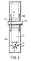
- the apparatus mainly consists of a driving wheel 10 defining a central hole 101, a driven shaft 12, a spool 15, a fan 16 and a bushing 102 defining a flange 103.
- the driven shaft 12 is formed to have an enlarged portion 13 on a circumferential periphery thereof.
- Six rollers 14 are attached on the enlarged portion 13, wherein the six rollers 14 are equally spaced from each other.
- the spool 15 and the fan 16 are fixedly mounted on an end of the driven shaft 12 via a nut (not shown) engaging with a threaded portion (not labeled) of the driven shaft 12.
- the driving wheel 10 is formed to have a groove-like profile along a central portion of a circumferential periphery thereof (better seen in Fig. 2).
- Fig. 2 shows that the driving wheel 10, the driven shaft 12 and the bushing 102 are assembled in a housing 20.
- the driven shaft 12 is rotatably mounted in the housing 20 at a predetermined position.
- the driving wheel 10 is mounted into the housing 20 to a position that one of the guiding channels 11 (better seen in Figs. 3 to 6) defined on the circumferential periphery of the driving wheel 10 is slideably engaged with one of the rollers 14.
- the bushing 102 is inserted into the central hole 101 to fixedly engage with a driving shaft 104 of the driving wheel 10.
- Figs. 3 to 6 show that a plurality of guiding channels 11 are defined in the circumferential periphery of the driving wheel 10.
- a first arc-shaped guiding channel is defined on a central portion of the circumferential periphery of the driving wheel 10.
- the first arc-shaped guiding channel extends from a right, upper corner of the circumferential periphery of the driving wheel 10 through a left side to a right, lower corner thereof.
- the other guiding channels are formed to respectively have a curved configuration with a different curvature.
- the other guiding channels which are located above the first arc-shaped guiding channel, each have an orientation extending from the left side of the circumferential periphery of the driving wheel 10 upwardly to a right side thereof and define a curve having a concave side substantially facing a right and lower portion of the circumferential periphery of the driving wheel 10.
- the other channels which are located below the first arc-shaped guiding channel, each have an orientation extending from the left side of the circumferential periphery of the driving wheel 10 downwardly to the right side thereof and define a curve having a concave side substantially facing a right, upper portion of the circumferential periphery of the driving wheel 10.
- the first arc-shaped guiding channel has a length which is the longest of the other guiding channels in Fig. 3.
- the other guiding channels have lengths and curvatures respectively gradually decreasing in proportion to their distances from the first arc-shaped guiding channel.
- Fig. 4 shows that the driving wheel 10 is rotated about 45* from Fig. 3, wherein the driving wheel 10 is rotated clockwise as viewed from Fig. 1.
- the top guiding channel in Fig. 4 is a lower portion of the first arc-shaped guiding channel of Fig. 3.
- there is a first horizontal guiding channel which is horizontally extended and located amid the first arc-shaped guiding channel and a second arc-shaped guiding channel (Fig. 5).
- the guiding channels each have a length and curvature gradually decreasing in proportion to their distances from the first arc-shaped guiding channel, and define a cure having a concave side substantially facing a right, upper portion of the circumferential periphery of the driving wheel 10 and have an orientation extending from the left side of the circumferential periphery of the driving wheel 10 downwardly to the right side thereof.
- the other guiding channels which are located below the first horizontal guiding channel each have a length and curvature gradually increasing in proportion to their distances from the first horizontal guiding channel, and define a cure having a concave side substantially facing a left, lower portion of the circumferential periphery of the driving wheel 10 and have an orientation also extending from the left side the circumferential periphery of the driving wheel 10 downwardly to the right side thereof.
- Fig. 5 shows that the driving wheel 10 is further rotated about 45* from Fig. 4.
- the second arc-shaped guiding channel as shown in Fig. 5 is located on a central portion of the circumferential periphery of the driving wheel 10 and extends from a left, upper corner of the circumferential periphery of the driving wheel 10 through a right side to a left, lower corner thereof.
- the other guiding channels, which are located above the second arc-shaped guiding channel each have an orientation extending from the left side of the circumferential periphery of the driving wheel 10 downwardly to a right side thereof and define a curve having a concave side substantially facing a left and lower portion of the circumferential periphery of the driving wheel 10.
- the other channels which are located below the second arc-shaped guiding channel, each have an orientation extending from the left side of the circumferential periphery of the driving wheel 10 upwardly to the right side thereof and define a curve having a concave side substantially facing a left, upper portion of the circumferential periphery of the driving wheel 10.
- the second arc-shaped guiding channel has a length which is the longest of the other guiding channels in Fig. 5 and is equal to that of the first arc-shaped guiding channel.
- the other guiding channels have lengths and curvatures respectively gradually decreasing in proportion to their distances from the second arc-shaped guiding channel.
- Fig. 6 shows that the driving wheel 10 is further rotated about 45* from Fig. 5.
- the top guiding channel in Fig. 6 is a lower portion of the second arc-shaped guiding channel in Fig. 5.
- the guiding channels each have a length and curvature gradually decreasing in proportion to their distances from the second arc-shaped guiding channel, and define a cure having a concave side substantially facing a left, upper portion of the circumferential periphery of the driving wheel 10 and have an orientation extending from the left side of the circumferential periphery of the driving wheel 10 upwardly to the right side thereof.
- the other guiding channels which are located below the second horizontal guiding channel in Fig.
- each have a length and curvature gradually increasing in proportion to their distances from the second horizontal guiding channel, and define a cure having a concave side facing a right, lower portion of the circumferential periphery of the driving wheel 10 and have an orientation also extending from the left side of the circumferential periphery of the driving wheel 10 upwardly to the right side thereof.
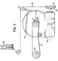
- Fig. 7 which shows that the driving shaft 104 of the driving wheel 10 is fixedly connected with a first belt pulley 21.
- a belt 22 is used to connect the first belt pulley 21 with a second belt pulley (not labeled) which is fixedly attached with an output shaft 23 of a motor (not shown) so that when the motor is started, the driving wheel 10 can rotate in one direction (for example, in a clockwise direction as viewed from Fig. 7).
- one of the rollers 14 of the driven shaft 12 is engaged with the first arc-shaped guiding channel as shown in Fig.
- the speed of rotation of the driven shaft 12 is decelerated with the same direction of rotation (i.e. clockwise) until one of the rollers 14 is engaged with and passing through the second arc-shaped guiding channel as shown in Fig. 5, in which the driven shaft 12 will substantially have no rotation.
- the shaft 12 and the spool 15 are again in a static state.
- the rollers 14 will sequentially engage the guiding channels below the second arc-shaped guiding channel as shown in Fig. 6, in which the driven shaft 12 will have a counterclockwise rotation as viewed from the left side of Fig.
- the driven shaft 12 and thus the spool 15 can obtain the following modes of movement: firstly in a static state, then, an acceleration in a first direction of rotation to reach a first maximum speed, a deceleration in the first direction to another static state, another acceleration in a second direction to reach a second maximum speed and finally another deceleration in the second direction to return to the first static state.
- a wire 30 has one end fixedly attached to the spool 15 and another end extending through a set of wire pulleys 31 to connect with a part 32 of a carriage (not shown) for driving a shuttle (not shown) by magnets (not shown).
- the driven shaft 12 and the spool 15 are bidirectionally pivoted by the driving wheel 10, the spool 15 can move the part 32 and thus the carriage in connection therewith to have a reciprocal movement via the wire 30 thereby to enable the shuttle motivated by the carriage to achieve a picking motion.
- the fan 16 is mounted near the spool 15 whereby an air flow generated by the fan 16 when it is rotated can dissipate heat generated between the wire 30 and the spool 15.
Landscapes
- Engineering & Computer Science (AREA)
- Textile Engineering (AREA)
- Looms (AREA)
Priority Applications (1)
| Application Number | Priority Date | Filing Date | Title |
|---|---|---|---|
| EP96113990A EP0826807A1 (fr) | 1996-09-02 | 1996-09-02 | Dispositif pour entraíner le chariot à navette d'un métier à tisser |
Applications Claiming Priority (1)
| Application Number | Priority Date | Filing Date | Title |
|---|---|---|---|
| EP96113990A EP0826807A1 (fr) | 1996-09-02 | 1996-09-02 | Dispositif pour entraíner le chariot à navette d'un métier à tisser |
Publications (1)
| Publication Number | Publication Date |
|---|---|
| EP0826807A1 true EP0826807A1 (fr) | 1998-03-04 |
Family
ID=8223150
Family Applications (1)
| Application Number | Title | Priority Date | Filing Date |
|---|---|---|---|
| EP96113990A Withdrawn EP0826807A1 (fr) | 1996-09-02 | 1996-09-02 | Dispositif pour entraíner le chariot à navette d'un métier à tisser |
Country Status (1)
| Country | Link |
|---|---|
| EP (1) | EP0826807A1 (fr) |
Citations (4)
| Publication number | Priority date | Publication date | Assignee | Title |
|---|---|---|---|---|
| FR2099494A1 (fr) * | 1970-07-21 | 1972-03-17 | Dewas Raymond | |
| BE877471Q (fr) * | 1977-08-06 | 1979-11-05 | Mertens & Frowein G M B H & Co | Commande de crochet pour metier a tisser double destine a la fabrication de velours, peluche et tapis |
| EP0162816A1 (fr) * | 1984-05-08 | 1985-11-27 | Mario Gonzi | Commande à mouvement cyclique rapide avec deux membres tournant par rapport à des axes non coplanaires |
| EP0391770A2 (fr) * | 1989-04-05 | 1990-10-10 | Chi-Shuang Huang | Dispositif de chasse pour métiers à tisser |
-
1996
- 1996-09-02 EP EP96113990A patent/EP0826807A1/fr not_active Withdrawn
Patent Citations (4)
| Publication number | Priority date | Publication date | Assignee | Title |
|---|---|---|---|---|
| FR2099494A1 (fr) * | 1970-07-21 | 1972-03-17 | Dewas Raymond | |
| BE877471Q (fr) * | 1977-08-06 | 1979-11-05 | Mertens & Frowein G M B H & Co | Commande de crochet pour metier a tisser double destine a la fabrication de velours, peluche et tapis |
| EP0162816A1 (fr) * | 1984-05-08 | 1985-11-27 | Mario Gonzi | Commande à mouvement cyclique rapide avec deux membres tournant par rapport à des axes non coplanaires |
| EP0391770A2 (fr) * | 1989-04-05 | 1990-10-10 | Chi-Shuang Huang | Dispositif de chasse pour métiers à tisser |
Similar Documents
| Publication | Publication Date | Title |
|---|---|---|
| KR20060059819A (ko) | 냉각용 송풍 팬 및 영상 표시 장치 | |
| US7077629B2 (en) | Multi-fan assembly | |
| US7815539B2 (en) | Planetary transmission | |
| KR101682900B1 (ko) | 차량용 풀리의 신뢰성 시험장치 | |
| CN110900591A (zh) | 绳驱机器人及设备 | |
| KR102084081B1 (ko) | 자전거용 다단기어 변속모터 | |
| CN213971203U (zh) | 驱动机构及机器人 | |
| US5697404A (en) | Rotary to reciprocating drive for a magnetic shuttle carriage | |
| CN108724160B (zh) | 一种提高控制精度的绳索驱动装置 | |
| EP0826807A1 (fr) | Dispositif pour entraíner le chariot à navette d'un métier à tisser | |
| CN108999798B (zh) | 风扇 | |
| US2708373A (en) | Power transmitting device | |
| US3204480A (en) | Motion and power transmission means | |
| KR101688181B1 (ko) | 오퍼레이션 패널을 구비한 차량용 풀리의 신뢰성 시험시스템 | |
| US5470199A (en) | Adjustment device for propeller pumps | |
| KR20160125642A (ko) | 웜 감속기 | |
| CN111037545A (zh) | 一种绳驱式串联机械臂 | |
| US20130251521A1 (en) | Diffusion Type Fan Device | |
| CN215344200U (zh) | 一种传动装置和轴承压装设备 | |
| CN209587081U (zh) | 一种超长丝杆传动装置 | |
| WO2008150077A1 (fr) | Mécanisme d'entraînement contrarotatif | |
| CN211311819U (zh) | 一种曲折缝纫机传动机构 | |
| CN115638222B (zh) | 一种带花键一体式的半封闭式滚珠丝杆 | |
| KR102778153B1 (ko) | 마그네틱 기어 기반 풍력발전기용 변속시스템 | |
| KR950009264Y1 (ko) | 모터 팬의 알피엠(rpm) 가변장치 |
Legal Events
| Date | Code | Title | Description |
|---|---|---|---|
| PUAI | Public reference made under article 153(3) epc to a published international application that has entered the european phase |
Free format text: ORIGINAL CODE: 0009012 |
|
| 17P | Request for examination filed |
Effective date: 19960902 |
|
| AK | Designated contracting states |
Kind code of ref document: A1 Designated state(s): BE CH DE ES FR GB GR IT LI LU NL SE |
|
| AKX | Designation fees paid |
Free format text: BE CH DE ES FR GB GR IT LI LU NL SE |
|
| RBV | Designated contracting states (corrected) |
Designated state(s): BE CH DE ES FR GB GR IT LI LU NL SE |
|
| GRAG | Despatch of communication of intention to grant |
Free format text: ORIGINAL CODE: EPIDOS AGRA |
|
| 17Q | First examination report despatched |
Effective date: 19990225 |
|
| STAA | Information on the status of an ep patent application or granted ep patent |
Free format text: STATUS: THE APPLICATION IS DEEMED TO BE WITHDRAWN |
|
| 18D | Application deemed to be withdrawn |
Effective date: 19990401 |