EP0826826A1 - Eisenbahnschienenbefestigung - Google Patents
Eisenbahnschienenbefestigung Download PDFInfo
- Publication number
- EP0826826A1 EP0826826A1 EP97306558A EP97306558A EP0826826A1 EP 0826826 A1 EP0826826 A1 EP 0826826A1 EP 97306558 A EP97306558 A EP 97306558A EP 97306558 A EP97306558 A EP 97306558A EP 0826826 A1 EP0826826 A1 EP 0826826A1
- Authority
- EP
- European Patent Office
- Prior art keywords
- clip
- rail
- passageway
- locating means
- passageways
- Prior art date
- Legal status (The legal status is an assumption and is not a legal conclusion. Google has not performed a legal analysis and makes no representation as to the accuracy of the status listed.)
- Granted
Links
- 238000004873 anchoring Methods 0.000 claims abstract description 57
- 230000000717 retained effect Effects 0.000 claims abstract description 6
- 239000012212 insulator Substances 0.000 claims description 37
- 239000000463 material Substances 0.000 claims description 4
- 238000012423 maintenance Methods 0.000 claims description 3
- 238000009434 installation Methods 0.000 description 7
- 238000000034 method Methods 0.000 description 5
- 241001669679 Eleotris Species 0.000 description 4
- 238000004519 manufacturing process Methods 0.000 description 4
- 238000005266 casting Methods 0.000 description 3
- 230000007423 decrease Effects 0.000 description 2
- 238000003780 insertion Methods 0.000 description 2
- 230000037431 insertion Effects 0.000 description 2
- 229910000831 Steel Inorganic materials 0.000 description 1
- 238000005452 bending Methods 0.000 description 1
- 230000000414 obstructive effect Effects 0.000 description 1
- 239000012858 resilient material Substances 0.000 description 1
- 230000000284 resting effect Effects 0.000 description 1
- 239000010959 steel Substances 0.000 description 1
Images







Classifications
-
- E—FIXED CONSTRUCTIONS
- E01—CONSTRUCTION OF ROADS, RAILWAYS, OR BRIDGES
- E01B—PERMANENT WAY; PERMANENT-WAY TOOLS; MACHINES FOR MAKING RAILWAYS OF ALL KINDS
- E01B9/00—Fastening rails on sleepers, or the like
- E01B9/02—Fastening rails, tie-plates, or chairs directly on sleepers or foundations; Means therefor
- E01B9/28—Fastening on wooden or concrete sleepers or on masonry with clamp members
- E01B9/30—Fastening on wooden or concrete sleepers or on masonry with clamp members by resilient steel clips
- E01B9/303—Fastening on wooden or concrete sleepers or on masonry with clamp members by resilient steel clips the clip being a shaped bar
-
- E—FIXED CONSTRUCTIONS
- E01—CONSTRUCTION OF ROADS, RAILWAYS, OR BRIDGES
- E01B—PERMANENT WAY; PERMANENT-WAY TOOLS; MACHINES FOR MAKING RAILWAYS OF ALL KINDS
- E01B2205/00—Electrical insulation of railway track parts
Definitions
- the present invention relates to fastening railway rails.
- rail clips commonly referred to respectively as a "P-R” clip (disclosed in GB-861,473) and an “e”-clip (disclosed in GB-1,510,224), have both been successful for many years, providing low-cost rail fastenings that have been widely used in many countries around the world.
- These clips may be installed into shoulders alongside the rail either manually, using a sledgehammer to drive the clip into the shoulder, or automatically by a clip driving machine. Whilst automatic clip installation is obviously more desirable, being quicker and less labour-intensive, it can be a fairly complex process, requiring accurate positioning of the clip relative to the shoulder in order to achieve an adequate rail fastening.
- a shoulder for use with a railway rail-fastening clip which is approximately M-shaped in plan and has first and second leg portions and a rail-bearing portion.
- the shoulder comprises a base member and first and second clip-retaining members, connected together by the base member such that the first clip-retaining member is spaced apart from the second clip-retaining member so as to define between the first and second clip-retaining members an opening for receiving the rail-bearing portion of such a clip.
- Each of the first and second clip-retaining members defines a passageway for receiving one of the leg portions of such a clip, a boundary surface of at least one of the passageways including first locating means for engagement, when the device is in use with such a clip, with a first region of the leg portion of the clip located in the passageway such that the clip can be held in a pre-assembly position in which the clip is retained by the device but the rail-bearing portion of the clip does not bear on a rail.
- Second locating means are also provided on a boundary surface of at least one of the passageways for engagement with a second region of the leg portion of the clip located in the passageway such that the clip can be held in a working position in which the rail-bearing portion of the clip bears on the rail, the first and second locating means being such that the clip cannot move out of the pre-assembly position towards a rail unless driven in a first direction and the clip cannot move out of the working position away from the rail unless driven in a second direction, opposite to the first direction.
- a railway rail anchoring device for use with a railway rail-fastening clip which is approximately M-shaped in plan and has first and second leg portions and a rail-bearing portion
- the device comprising a base member and first and second clip-retaining members connected together by the said base member such that the first clip-retaining member is spaced apart from the second clip-retaining member so as to define between the said first and second clip-retaining members an opening for receiving the said rail-bearing portion of such a clip; each of the said first and second clip-retaining members defining a passageway for receiving one of the leg portions of such a clip; and a boundary surface of at least one of the said passageways including first locating means for engagement, when the device is in use with such a clip, with a first region of the leg portion of the clip located in the said passageway such that the clip can be held in a pre-assembly position in which the clip is retained by the device but the rail-bearing portion of the clip does not bear
- an anchoring device embodying the present invention can be made using a simple and inexpensive casting technique, thereby reducing manufacturing costs.
- third locating means are provided in the said opening defined between the said first and second clip-retaining members for engagement with a locating region of a toe insulator of such a clip so that the clip can be held in a maintenance position in which the clip does not bear on the rail and the said first region of the leg portion of the clip does not engage with the said first locating means of the device.
- a rail fastening assembly comprising a railway rail fastening clip suitable for holding down a railway rail, and an anchoring device, the clip being formed of a rod of material bent such that the clip is approximately M-shaped in plan, having first and second leg portions formed to cooperate with part of the anchoring device so as to locate the clip in the anchoring device, and also having a rail-bearing portion formed between the first and second leg portions, the anchoring device comprising a base member and first and second clip-retaining members connected together by the said base member such that the first clip-retaining member is spaced apart from the second clip-retaining member so as to define between the said first and second clip-retaining members an opening for receiving the said rail-bearing portion of such a clip; each of the said first and second clip-retaining members defining a passageway for receiving one of the leg portions of such a clip, and a boundary surface of at least one of the said passageways including first locating means for engagement with a first region of the leg portion of the clip
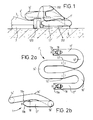
- Fig. 1 shows a rail-fastening assembly known from Australian Patent No. 665971 and European Patent No. 0619851, which assembly comprises a resilient railway rail-fastening clip 1' having a toe portion 14' which bears against a flange of a railway rail 3 supported by a rail foundation 6, the rail foundation 6 being cushioned from the rail 3 by means of a resilient rail pad 7 located between the base of the rail and the rail foundation 6.
- the rail clip 1' is held in place by an anchoring device or shoulder 250, the shoulder 250 having a pair of passageways 253 (only one of which is shown in Fig. 1) in which respective limbs 11', 17' (only limb 17' being shown in Fig. 1) of the clip are located.
- the toe portion 14' of the clip 1' carries an insulator 4' covering the lowermost surface of the toe portion 14', so that the toe portion 14' of the clip 1' bears on the rail flange through the insulator 4', which thereby insulates the clip 1' from the rail 3.
- a "side post" insulator 570 Located between the rail 3 and the shoulder 250 is a "side post" insulator 570, for electrically isolating the shoulder 250 from the rail 3.
- the clip 1' shown in Fig. 1 is substantially M-shaped in plan. It is made by bending a rod of resilient material, which is, in this case, circular in cross-section (for example a steel rod 15mm in diameter), so as to have, proceeding from one end A of the rod to the other end B, a straight first portion 11', a second portion 12' bent through 180°, a curved third portion 13', a fourth portion 14' which is bent through 180°, a curved fifth portion 15', a sixth portion 16' which is bent through 180° and a straight seventh portion 17'.
- a rod of resilient material which is, in this case, circular in cross-section (for example a steel rod 15mm in diameter)
- the first and seventh portions 11' and 17' of the clip constitute the outer legs of the M
- the third and fifth portions 13' and 15' constitute the inner legs of the M
- the second and sixth portions 12' and 16' join respective inner legs to the outer legs
- the fourth portion 14' of the clip joins together the inner legs.
- the fourth portion 14' of the clip extends beyond the free ends A and B of the first and seventh portions 11' and 17'.
- a plane containing the longitudinal axis of the fourth portion 14' is substantially parallel to the plane containing the first and seventh portions 11' and 17'.
- the outer legs of the clip i.e. the first and seventh portions 11' and 17' thereof, are each provided with detents 18 on their upper surface adjacent to the respective free ends A and B of the clip.
- Each free end A,B of the clip 1' is tapered on its upper and lower surfaces, the upper and lower tapered surfaces 19a, 19b being at an angle of approximately 30° with respect to the longitudinal axis of the clip.
- the detent 18 is formed just behind the tapered part 19a of the upper surface.
- the taper 19a on the upper surface of the outer leg is intended to ease insertion of the clip 1' into an anchoring device 250.
- the taper 19b on the lower surface of the outer leg is intended to facilitate use of the clip in holding the insulator 570 in place between the anchoring device 250 and the rail 3.
- Figs. 2a and 2b has heretofore been used, as shown in Fig. 1, with an anchoring device as shown in more detail in Figs. 3a to 3c.
- the anchoring device 250 of Figs. 3a to 3c comprises a base member 251, which extends substantially horizontally when the device is in use, and a pair of clip-retaining members 252 which are connected at one end thereof to either end of the base member 251 so as to extend substantially perpendicularly thereto both vertically and horizontally.
- a channel formed in the outwardly-facing wall of each clip-retaining member 252 provides a passageway 253 for receiving the outer legs of the clip of Figs. 2a and 2b.
- the clip-retaining members 252 are spaced apart by the base member 251 so as to define an opening 254 therebetween for receiving the inner legs of the clip.
- each passageway 253 has an opening 256 at the end of the clip retaining member 252 which is furthest from the base member 251, but is closed by a wall 257 at the other end of the clip-retaining member 252 so as to provide means by which the insulator 570 may be located on the anchoring device 250. For this purpose also, the roof of the passageway adjacent to the wall 257 is removed.
- the passageway 253 When the anchoring device 250 is in use, the floor of the passageway 253 is substantially horizontal.
- the passageway 253 has only one side face, constituted by a wall 252a of the clip-retaining member 252 formed so as to lie between the outer and inner legs of the clip 1' when in use, the other side of the passageway being open.
- the roof of the passageway 253 is formed so as to have a sloping part 253a which is inclined with respect to the horizontal when the device is in use such that the passageway is taller at the part of that sloping part 253a which is closer to the opening 256 than it is at the other end of the part 253a, the roof of the passageway 253 being formed at either end of the sloping part 253a in such a way as to provide projections 253b and 253c for cooperating with the detent 18 formed in the outer leg of each clip 1' for locating the clip 1' at a particular location with respect to the anchoring device 250.
- each wall 252a of the clip-retaining members 252 Extending from each wall 252a of the clip-retaining members 252 in a region above the passageways 253 is a part 258 such that between the passageway 253 and the part 258 there is defined a recess 259 into which a tool, for installing a clip into or removing a clip from the device, or for lifting a sleeper to which a pair of anchoring devices 250 have been secured, may be inserted.
- the roof of the recess 259 may be sloped along one edge as shown.
- the wall 252a of each clip-retaining member 252 may be rounded or sloped along one edge as shown so as to reduce the amount of material required to make the anchoring device 250.
- the floor of the passageway 253 is preferably extended beyond the opening 256 so as to provide a part 253d against which the lower surface of the outer legs of the clip may rest when the clip is about to be installed in the device 250.
- Fig. 4a shows the clip in an initial position, as it is when it is about to be driven into the device 250, with the fourth portion of the clip 1' resting (via a toe insulator 4', not shown) on the base member 251 of the anchoring device 250 and the outer legs of the clip 1' just inside the passageways 253 of the anchoring device 250 such that part of the lower surface of the outer legs rests on the portion 253d of the anchoring device 250, the face 18a of the detent 18 which is closest to the free end of the outer leg is in contact with a face 253b" of the projection 253b, and the upper tapered surface 19a of the outer leg is partly in contact with the sloping part 253a of the roof of the passageway 253.
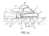
- Fig. 4c shows the clip as it appears when it has been driven from the intermediate position shown in Fig. 4b into a final position where the fourth portion 14' (normally carrying a toe insulator 4') of the clip 1' bears on the rail 3.
- the sloping roof of the passageway in contact with the upper tapered surface 19a of the outer leg urges the outer leg downwardly, thereby deflecting the clip.
- the detent 18 in the clip 1' is engaged by the second projection 253c of the anchoring device 250 and the free ends of the outer legs overlie the locating feet 576 of the side post insulator 570 so that upward movement of the insulator 570 is further restricted.
- the clip is fully deflected in this position, the fourth portion of the clip lying in a plane which is substantially parallel to the plane containing the first and seventh portions of the clip and the second and sixth portions 12' and 16' of the clip being at their highest point.
- the insulator When the clip is in its initial position, the insulator is free to move upwardly, to facilitate replacement of the insulator 570 if required.
- an anchoring device embodying the present invention can be manufactured using a simple and inexpensive casting technique.
- an anchoring device embodying the present invention the non-vertical surfaces are inclined with respect to a horizontal plane and there are no obstructive projections, so that a simple two-part mould can be used to produce the device.
- Such a design offers significant improvements over the earlier devices.
- locating means for locating the railway rail clip in a "parked" position before the assembly is fitted on the railway track installation are constituted by an abutment surface provided in the roof of the passageway intermediate the ends thereof.
- an upstand member is provided to allow the clip to be placed in an "insulator change" position, in which the side post insulator may be removed, without the need for the complete removal of the clip from the anchoring device (thereby facilitating maintenance of the track installation).
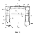
- the anchoring device 300 of Figures 5a to 5c comprises a base member 301, which extends substantially horizontally when the device is in use, and a pair of clip-retaining members 304.
- Each clip-retaining member 304 is connected at one end thereof to the base member 301 and extends substantially perpendicularly thereto both vertically and horizontally when the device is in use.
- the clip-retaining members 304 are spaced apart on the base member 301 so as to define an opening 310 therebetween for receiving the inner legs of the clip shown in Figs. 2a and 2b.
- a channel formed in the outer face of each clip-retaining member 304 provides a passageway 309 for receiving respective outer legs of the clip of Figures 2a and 2b.
- Each passageway 309 has an opening 311 at one end thereof and is partially closed by a wall 312 at the other end of the clip retaining member 304 so as to provide means by which an insulator 570' may be located on the anchoring device 300, as will be explained later in more detail.
- the roof of the passageway adjacent to the wall 312 is removed.
- the floor of the passageway 309 is substantially horizontal.
- the passageway 309 has only one side boundary surface, constituted by a wall 313 of the clip-retaining member 304 formed so as to lie between the outer and inner legs of the clip 1' when in use.
- the other side of the passageway is open.
- the roof of the passageway 309 is formed, at a location intermediate respective ends of the passageway, so as to have a sloping part 314 which is inclined with respect to the horizontal when the device is in use such that the passageway is taller at the part of that sloping part 314 which is closer to the opening 311 than it is at the other end of the part 314.
- each passageway 309 is formed, at a location intermediate respective ends of the passageway, so as to define an abutment surface 305 which engages with a first region constituted by a free end 19, of the inserted outer leg portion of the clip 1', when the clip is held in a pre-assembly position in the device 300, as will be explained below in more detail.
- the passageway roof 314 ends, closest to the wall 312, at a corner region 306 providing locating means which engage with a second region 18 of the clip 1', when the clip is in a working position, as will be explained in more detail below.
- each wall 313 of the clip retaining members 304 Extending from each wall 313 of the clip retaining members 304 in a region above the passageways 309 is a part 315 such that between the passageway 309 and the part 315 there is defined a recess 316 into which a tool, for installing a clip into or removing the clip from the device, or for lifting a sleeper to which a pair of anchoring devices 300 has been secured, may be inserted.
- the roof of the region 316 may be sloped along one edge as shown.
- the wall 313 of each clip retaining member 304 may be rounded or sloped along one edge as shown so as to reduce the amount of material required to make the anchoring device 300.
- the floor of passageway 309 is preferably extended beyond the opening 311 so as to provide a part 301a against which the lower surface of the outer leg of the clip may rest when the clip is about to be installed in the device 300.
- the base member 301 which provides a support for the fourth portion 14' of the clip 1' when it is not bearing on the rail, is in this embodiment intended (when in use) to receive a side post insulator 570', a step 318 being provided in the face of the base member 301 which is closest to the rail 3 when the device 300 is in use for receiving a horizontally-extended part of the insulator 570'. It should be noted however that this step 318 would not be required if the anchoring device 300 were to be used with a conventional insulator for electrically isolating the device from the rail.
- the overall height of the anchoring device is 60 mm and its overall width is 101 mm.
- the clip-retaining members 304 define an opening between them which is 57 mm wide, the wall 313 being 9 mm wide.
- the part 301a extends beyond the opening 311 of the passage 309 by a distance 11 mm, the length of the passageway from the inner wall 312 to the opening 311 being 77 mm.
- the wall 312 is 8 mm thick as measured in a direction parallel to the length of the passageway 309, and is 21 mm high.
- the thickness of the floor of the passageway is 10 mm and the height of the passageway at the opening is 23 mm.
- the height of the passageway then decreases at an angle of about 5° to the abutment surface 305, which projects 1 to 2 mm from the passageway roof.
- the height of the passageway roof then decreases further at an angle of about 5° to a final height, at its lowermost point, of 18.5 mm above the floor of the passageway 209.
- the corner region 306 is defined.
- the step 318 formed in the base member 301 is formed so as to be 15 mm above the lowermost point of the anchoring device and is of depth 8 mm.
- the anchoring device 300 is provided with a intermediate portion 307 which links the two clip-retaining members 304 across the space 310.
- the portion 307 includes a projection 308 which projects upwardly from the portion 307.
- the projection 308 is for engagement with a part of the toe insulator 400 (as shown in Fig. 6c), which will be explained later.
- the anchoring device 300 is provided with a pair of anchoring legs 302 which are for securing the device to a sleeper when in use. It is possible to have one or two such legs 302.
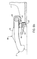
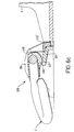
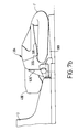
- Figures 6a and 7a show an anchoring device with a clip in a preassembly position.
- the resilience of the clip holds it in place in the anchoring device, and insulators 400 and 570' are held in place by the clip 1'.
- the clip is held in the preassembly position before being driven into a working position in the device 300.
- the first region 19 (which, as shown in Fig. 7a for example, is preferably slightly rounded) of the clip leg 11 (17) is held in abutting engagement with the abutment surface 305.
- the fourth portion of the clip 11 rests (via a part 401 of a toe insulator 400) on the portion 307 of the base member 301, and the outer legs of clip 1' lie inside respective passageways 309 of the anchoring device 300 such that respective end regions 19a' of those outer legs are in abutting engagement with respective notches 305.
- the clip is only partially deflected, for example only 6 mm out of a possible total deflection of 12 mm.
- the clip does not bear on the rail 3.
- the clip has a third position in the anchoring device 300, shown in Figures 6c and 7c, into which the clip may be driven outwardly from the rail, so that a detent 401 in the underside of the toe insulator 400 is brought into engagement with the projecting member 308 of the intermediate portion 307.
- the engagement of the toe insulator 400 with the projection 308 holds the clip in place, whilst allowing the side post insulator 570' to be removed from the assembly.
- this embodiment of the present invention allows the clip to be positioned in an "insulator-change" position, in which the side post insulator can be removed without the need for removal of the clip from the assembly or the removal of the assembly from the railway installation.
Landscapes
- Engineering & Computer Science (AREA)
- Mechanical Engineering (AREA)
- Architecture (AREA)
- Civil Engineering (AREA)
- Structural Engineering (AREA)
- Railway Tracks (AREA)
- Clamps And Clips (AREA)
Applications Claiming Priority (2)
| Application Number | Priority Date | Filing Date | Title |
|---|---|---|---|
| US705672 | 1996-08-30 | ||
| US08/705,672 US5735458A (en) | 1991-12-18 | 1996-08-30 | Fastening railway rails |
Publications (2)
| Publication Number | Publication Date |
|---|---|
| EP0826826A1 true EP0826826A1 (de) | 1998-03-04 |
| EP0826826B1 EP0826826B1 (de) | 2001-08-08 |
Family
ID=24834477
Family Applications (1)
| Application Number | Title | Priority Date | Filing Date |
|---|---|---|---|
| EP97306558A Expired - Lifetime EP0826826B1 (de) | 1996-08-30 | 1997-08-27 | Eisenbahnschienenbefestigung |
Country Status (4)
| Country | Link |
|---|---|
| US (1) | US5735458A (de) |
| EP (1) | EP0826826B1 (de) |
| AU (1) | AU718771B2 (de) |
| DE (1) | DE69706006T2 (de) |
Cited By (6)
| Publication number | Priority date | Publication date | Assignee | Title |
|---|---|---|---|---|
| RU2235159C2 (ru) * | 2002-03-04 | 2004-08-27 | Закрытое Акционерное Общество "Трансроуд Груп" | Устройство "трансроуд груп" для крепления рельса к шпале |
| RU2280725C2 (ru) * | 2004-10-29 | 2006-07-27 | Закрытое Акционерное Общество "Трансроуд Груп" | Крепление рельс к шпале |
| RU2280724C2 (ru) * | 2004-04-02 | 2006-07-27 | Закрытое Акционерное Общество "Трансроуд Груп" | Устройство для крепления рельса к шпале |
| GB2435285A (en) * | 2006-02-21 | 2007-08-22 | Pandrol Ltd | Fastening railway rails |
| WO2019197075A1 (en) * | 2018-04-11 | 2019-10-17 | Pandrol Limited | An anchoring device for a railway rail fastening assembly |
| RU205472U1 (ru) * | 2020-01-27 | 2021-07-15 | Владимир Николаевич Шимко | Анкер рельсового скрепления |
Families Citing this family (12)
| Publication number | Priority date | Publication date | Assignee | Title |
|---|---|---|---|---|
| RU2137874C1 (ru) * | 1998-07-10 | 1999-09-20 | Арендное предприятие "Минский подшипниковый завод" | Устройство для крепления железнодорожного рельса |
| CA2270299A1 (en) * | 1998-10-14 | 2000-04-14 | Jude Igwemezie | Rail retaining device |
| US6367704B1 (en) | 2000-06-28 | 2002-04-09 | Airboss Railway Products, Inc. | Rail fastening system constructed to allow pre-assembly of a rail clip and shoulder |
| RU2230146C2 (ru) * | 2001-10-04 | 2004-06-10 | Сибирский государственный университет путей сообщения | Устройство для крепления рельса к железобетонному основанию |
| US7690584B2 (en) * | 2002-12-03 | 2010-04-06 | Pandrol Limited | Fastener for supporting railroad ties |
| EA010041B1 (ru) * | 2004-07-01 | 2008-06-30 | Фоссло-Верке Гмбх | Упорный вкладыш и система рельсового скрепления |
| DE102005048829A1 (de) * | 2004-12-09 | 2006-06-29 | SCHWIHAG GESELLSCHAFT FüR EISENBAHNOBERBAU MBH | Kraftschlüssig-elastische Schienenbefestigung für Gleisanlagen |
| US8052068B1 (en) * | 2010-05-10 | 2011-11-08 | Vossloh-Werke Gmbh | Guide plate for laterally guiding a rail and system for fastening a rail to a base |
| GB2502990B (en) * | 2012-06-12 | 2018-01-31 | Pandrol Ltd | Railway rail fastening clip for recessed railseats |
| US9228297B2 (en) | 2012-11-28 | 2016-01-05 | Pandrol Limited | Rail support assembly with improved shoulder |
| RU2557098C1 (ru) * | 2014-12-30 | 2015-07-20 | Борис Владимиленович Наумов | Рельсовое скрепление |
| US10815623B2 (en) | 2017-07-17 | 2020-10-27 | Pandrol Limited | Apparatus and method for repairing worn rail shoulders |
Citations (1)
| Publication number | Priority date | Publication date | Assignee | Title |
|---|---|---|---|---|
| US5520330A (en) * | 1991-12-18 | 1996-05-28 | Pandrol Limited | Railway rail-fastening clip and assembly and methods of employing the same |
Family Cites Families (51)
| Publication number | Priority date | Publication date | Assignee | Title |
|---|---|---|---|---|
| DE658902C (de) * | 1938-04-19 | Carl Loessl | Schienenbefestigung mittels in Schienenfuehrungsrippen abgestuetzter Klemmplatten | |
| US2162365A (en) * | 1937-11-04 | 1939-06-13 | George T Willard | Railway tie plate and clip |
| US2570871A (en) * | 1947-06-05 | 1951-10-09 | United States Steel Corp | Rail fastening device |
| BE534458A (de) * | 1954-01-21 | |||
| GB861473A (en) * | 1956-08-03 | 1961-02-22 | Lockspike Ltd | Improvements in fastening members for anchoring railway rails and in rail-fastening arrangements employing such members |
| DE1061810B (de) * | 1957-05-14 | 1959-07-23 | Johan Frederik Deenik Dipl Ing | Befestigungsvorrichtung fuer auf starren Unterlagen zwischen seitlichen Anschlaegen liegende Eisenbahn-schienen mittels einer federnden Klemme |
| US2954169A (en) * | 1957-06-04 | 1960-09-27 | Mills James Ltd | Rail fastening |
| AT249098B (de) * | 1965-04-07 | 1966-09-26 | Oesterr Alpine Montan | Schienenbefestigung unter Verwendung von Rippenplatten |
| DE1257817B (de) * | 1965-11-25 | 1968-01-04 | Meier Hermann Dr Ing | Schienenbefestigung auf Betonschwellen od. dgl. |
| DE1261151B (de) * | 1966-10-29 | 1968-02-15 | Meier Hermann Dr Ing | Schienenbefestigung mittels elastischer Klemme |
| FR2040755A5 (de) * | 1969-04-11 | 1971-01-22 | Vagneux Traverses Beton | |
| DE6946716U (de) * | 1969-12-01 | 1970-04-16 | Markmann & Moll K G Fa | Klemmplatte |
| GB1327814A (en) * | 1970-02-20 | 1973-08-22 | Molyneux G | Anchorages for track rails |
| US3696998A (en) * | 1970-12-09 | 1972-10-10 | Padinjarai Madom Narayanan Nai | Device for holding down the rail to the sleeper in a railway track |
| US3970248A (en) * | 1972-09-12 | 1976-07-20 | George Molyneux | Combined rail clip and anchorage |
| GB1475989A (en) * | 1973-05-21 | 1977-06-10 | French M | Clip devices |
| GB1510224A (en) * | 1975-11-07 | 1978-05-10 | Pandrol Ltd | Railway rail fastening clip and a railway rail-and-fastening assembly employing it |
| GB1553793A (en) * | 1977-11-07 | 1979-10-10 | Portec Inc | Rail fastener |
| FR2436848A1 (fr) * | 1978-05-22 | 1980-04-18 | Ferroviaires Soc | Dispositif d'attache elastique de voies ferrees |
| NL7806398A (nl) * | 1978-06-13 | 1979-12-17 | Everts & Van Der Weyden Nv | Houder voor een geleidingsconstructie. |
| US4278204A (en) * | 1978-11-29 | 1981-07-14 | Pandrol Limited | Rail clip |
| NL7903569A (nl) * | 1979-05-07 | 1980-11-11 | Everts & Van Der Weyden Nv | Bevestigingshuis voor een railklem en werkwijze ter vervaardiging van een betonnen dwarsligger met bevestigingshuis. |
| DE2965802D1 (en) * | 1979-07-05 | 1983-08-04 | Mckay Ralph Ltd | A rail fastener |
| JPH0132321B2 (de) * | 1979-07-05 | 1989-06-30 | Raifu Matsukei Ltd | |
| NL7906455A (nl) * | 1979-08-28 | 1981-03-03 | Everts & Van Der Weyden Nv | Railklem. |
| DE2965999D1 (en) * | 1979-10-26 | 1983-09-01 | Mckay Ralph Ltd | A rail clip holder |
| DE3003881A1 (de) * | 1980-02-02 | 1981-08-13 | Karl Richtberg Kg, 6530 Bingen | Spannbuegel fuer kraftschluessige und elastisch nachgiebige schienenbefestigungen mit formschluessigem seitenhalt von gleisanlagen |
| DE3003867A1 (de) * | 1980-02-02 | 1981-09-10 | Karl Richtberg Kg, 6530 Bingen | Kraftschluessige und elastisch nachgiebige schienenbefestigung fuer gleisanlagen |
| HU182120B (en) * | 1980-04-03 | 1983-12-28 | Schmitthelm Fa Ernst | Flexible rail fastening device for concrete sleepers |
| GB2075580A (en) * | 1980-05-06 | 1981-11-18 | Pandrol Ltd | Securing railway rails |
| DE3152271A1 (en) * | 1980-08-20 | 1982-10-07 | Mckay Ltd R | Rail fastening system |
| GB2085057B (en) * | 1980-09-29 | 1984-05-16 | Pandrol Ltd | A rail clip and an assembly on a railway track which includes the clip |
| PL128477B1 (en) * | 1981-05-15 | 1984-01-31 | Polskie Koleje Panstwowe | Device for attaching a rail to a supporting member in particular that made of concrete |
| GB2106571A (en) * | 1981-09-18 | 1983-04-13 | Karmic Limited | Insulated rail clip |
| FI72776C (fi) * | 1983-05-30 | 1987-07-10 | Fiskars Ab Oy | Anordning foer faestande av en raels vid en syll. |
| ZA849298B (en) * | 1983-12-21 | 1985-07-31 | Mckay Ralph Ltd | Rail clip support |
| DE3400110A1 (de) * | 1984-01-04 | 1985-07-11 | Karl Richtberg GmbH & Co. KG, 6530 Bingen | Kraftschluessig-elastische schienenbefestigung fuer gleisanlagen |
| DE3411122A1 (de) * | 1984-03-26 | 1985-10-03 | BWG Butzbacher Weichenbau GmbH, 6308 Butzbach | Vorrichtung zum befestigen von schienen |
| DE3526653A1 (de) * | 1985-07-25 | 1987-02-05 | Vossloh Werke Gmbh | Schienenbefestigung mittels einer elastischen spannklemme |
| US4632308A (en) * | 1985-10-25 | 1986-12-30 | Portec, Inc. | Adjustable rail fastener assembly |
| DE3619417A1 (de) * | 1986-06-10 | 1987-12-17 | Salzgitter Peine Stahlwerke | Betonschwelle |
| US4832261A (en) * | 1987-02-09 | 1989-05-23 | Chemetron-Railway Products, Inc. | Railway rail fastening assembly |
| US4844337A (en) * | 1987-03-27 | 1989-07-04 | Chemetron-Railway Products, Inc. | Railway rail assembly |
| DE3720381A1 (de) * | 1987-06-19 | 1989-01-05 | Vossloh Werke Gmbh | Vorrichtung zur befestigung von eisenbahnschienen auf fester fahrbahn |
| DE8804426U1 (de) * | 1988-04-02 | 1988-05-11 | Laeis GmbH, 5500 Trier | Klemmvorrichtung zum Befestigen von Schienen innerhalb eines Gleises und einer Weiche, insbesondere auf Stahlschwellen |
| FR2647821B1 (fr) * | 1989-06-02 | 1991-09-20 | Allevard Ind Sa | Dispositif de fixation de rail de voie ferree sur un support |
| DE8906790U1 (de) * | 1989-06-02 | 1989-08-31 | Vossloh-Werke GmbH, 58791 Werdohl | Schienenbefestigung auf Betonschwellen od.dgl. mittels elastischer Spannklemmen |
| FR2649138B1 (fr) * | 1989-06-30 | 1996-10-11 | Allevard Ind Sa | Dispositif de fixation elastique d'un rail de chemin de fer sur son support |
| FR2657631B1 (fr) * | 1990-01-30 | 1997-05-09 | Allevard Ind Sa | Dispositif de fixation de rail de chemin de fer sur un support en beton ou en metal. |
| CA2067323A1 (en) * | 1991-05-02 | 1992-11-03 | Barry Marshall | Railway rail - fastening clip |
| DE4240347A1 (de) * | 1992-12-01 | 1994-06-09 | Hubmann Hanns Peter | Schienenbefestigungsvorrichtung |
-
1996
- 1996-08-30 US US08/705,672 patent/US5735458A/en not_active Expired - Lifetime
-
1997
- 1997-08-27 DE DE69706006T patent/DE69706006T2/de not_active Expired - Lifetime
- 1997-08-27 EP EP97306558A patent/EP0826826B1/de not_active Expired - Lifetime
- 1997-08-29 AU AU36085/97A patent/AU718771B2/en not_active Expired
Patent Citations (2)
| Publication number | Priority date | Publication date | Assignee | Title |
|---|---|---|---|---|
| US5520330A (en) * | 1991-12-18 | 1996-05-28 | Pandrol Limited | Railway rail-fastening clip and assembly and methods of employing the same |
| EP0619851B1 (de) * | 1991-12-18 | 1997-03-05 | Pandrol Limited | Eisenbahnschienenbefestigung |
Cited By (11)
| Publication number | Priority date | Publication date | Assignee | Title |
|---|---|---|---|---|
| RU2235159C2 (ru) * | 2002-03-04 | 2004-08-27 | Закрытое Акционерное Общество "Трансроуд Груп" | Устройство "трансроуд груп" для крепления рельса к шпале |
| RU2280724C2 (ru) * | 2004-04-02 | 2006-07-27 | Закрытое Акционерное Общество "Трансроуд Груп" | Устройство для крепления рельса к шпале |
| RU2280725C2 (ru) * | 2004-10-29 | 2006-07-27 | Закрытое Акционерное Общество "Трансроуд Груп" | Крепление рельс к шпале |
| GB2435285A (en) * | 2006-02-21 | 2007-08-22 | Pandrol Ltd | Fastening railway rails |
| US7845578B2 (en) | 2006-02-21 | 2010-12-07 | Pandrol Limited | Railway rail fastening clip |
| US7954727B2 (en) | 2006-02-21 | 2011-06-07 | Pandrol Limited | Anchoring devices for rail fastening clips |
| US8146835B2 (en) | 2006-02-21 | 2012-04-03 | Pandrol Limited | Sealing plate for railway rail clip anchoring device and sleeper manufacturing method |
| WO2019197075A1 (en) * | 2018-04-11 | 2019-10-17 | Pandrol Limited | An anchoring device for a railway rail fastening assembly |
| AU2019251560B2 (en) * | 2018-04-11 | 2023-06-29 | Pandrol Limited | An anchoring device for a railway rail fastening assembly |
| US11753774B2 (en) | 2018-04-11 | 2023-09-12 | Pandrol Limited | Anchoring device for a railway rail fastening assembly |
| RU205472U1 (ru) * | 2020-01-27 | 2021-07-15 | Владимир Николаевич Шимко | Анкер рельсового скрепления |
Also Published As
| Publication number | Publication date |
|---|---|
| AU718771B2 (en) | 2000-04-20 |
| EP0826826B1 (de) | 2001-08-08 |
| DE69706006D1 (de) | 2001-09-13 |
| AU3608597A (en) | 1998-03-05 |
| DE69706006T2 (de) | 2001-11-22 |
| US5735458A (en) | 1998-04-07 |
Similar Documents
| Publication | Publication Date | Title |
|---|---|---|
| EP0826826B1 (de) | Eisenbahnschienenbefestigung | |
| EP0619851B1 (de) | Eisenbahnschienenbefestigung | |
| JP5172712B2 (ja) | 鉄道のレールクリップ固定装置のための密封板、及び、枕木の製造方法 | |
| US4915299A (en) | Fastening railway rails | |
| CS235058B2 (en) | Clamp for fastening of railway rail | |
| JP4084928B2 (ja) | 枕木組立体及びその組立て方法 | |
| US4405081A (en) | Rail fastener with gauge adjustment | |
| US6398123B1 (en) | Railway fastening anchor and clip | |
| US4576334A (en) | Cast shoulder | |
| AU2019251560B2 (en) | An anchoring device for a railway rail fastening assembly | |
| AU752883B2 (en) | Preloading rail clips in steel sleepers | |
| AU5408701A (en) | A resilient clip for a rail | |
| AU5196400A (en) | A resilient fastening assembly for a rail |
Legal Events
| Date | Code | Title | Description |
|---|---|---|---|
| PUAI | Public reference made under article 153(3) epc to a published international application that has entered the european phase |
Free format text: ORIGINAL CODE: 0009012 |
|
| AK | Designated contracting states |
Kind code of ref document: A1 Designated state(s): DE FR GB IT SE |
|
| AX | Request for extension of the european patent |
Free format text: AL;LT;LV;RO;SI |
|
| 17P | Request for examination filed |
Effective date: 19980427 |
|
| AKX | Designation fees paid |
Free format text: DE FR GB IT SE |
|
| RBV | Designated contracting states (corrected) |
Designated state(s): DE FR GB IT SE |
|
| GRAG | Despatch of communication of intention to grant |
Free format text: ORIGINAL CODE: EPIDOS AGRA |
|
| GRAG | Despatch of communication of intention to grant |
Free format text: ORIGINAL CODE: EPIDOS AGRA |
|
| GRAH | Despatch of communication of intention to grant a patent |
Free format text: ORIGINAL CODE: EPIDOS IGRA |
|
| 17Q | First examination report despatched |
Effective date: 20001016 |
|
| GRAH | Despatch of communication of intention to grant a patent |
Free format text: ORIGINAL CODE: EPIDOS IGRA |
|
| GRAA | (expected) grant |
Free format text: ORIGINAL CODE: 0009210 |
|
| AK | Designated contracting states |
Kind code of ref document: B1 Designated state(s): DE FR GB IT SE |
|
| ITF | It: translation for a ep patent filed | ||
| REF | Corresponds to: |
Ref document number: 69706006 Country of ref document: DE Date of ref document: 20010913 |
|
| ET | Fr: translation filed | ||
| REG | Reference to a national code |
Ref country code: GB Ref legal event code: IF02 |
|
| PLBE | No opposition filed within time limit |
Free format text: ORIGINAL CODE: 0009261 |
|
| STAA | Information on the status of an ep patent application or granted ep patent |
Free format text: STATUS: NO OPPOSITION FILED WITHIN TIME LIMIT |
|
| 26N | No opposition filed | ||
| REG | Reference to a national code |
Ref country code: GB Ref legal event code: 732E Free format text: REGISTERED BETWEEN 20120621 AND 20120627 |
|
| REG | Reference to a national code |
Ref country code: DE Ref legal event code: R082 Ref document number: 69706006 Country of ref document: DE Representative=s name: HASELTINE LAKE LLP, DE |
|
| REG | Reference to a national code |
Ref country code: FR Ref legal event code: PLFP Year of fee payment: 20 |
|
| PGFP | Annual fee paid to national office [announced via postgrant information from national office to epo] |
Ref country code: GB Payment date: 20160823 Year of fee payment: 20 Ref country code: IT Payment date: 20160822 Year of fee payment: 20 Ref country code: DE Payment date: 20160823 Year of fee payment: 20 |
|
| PGFP | Annual fee paid to national office [announced via postgrant information from national office to epo] |
Ref country code: FR Payment date: 20160816 Year of fee payment: 20 Ref country code: SE Payment date: 20160822 Year of fee payment: 20 |
|
| REG | Reference to a national code |
Ref country code: DE Ref legal event code: R071 Ref document number: 69706006 Country of ref document: DE |
|
| REG | Reference to a national code |
Ref country code: GB Ref legal event code: PE20 Expiry date: 20170826 |
|
| REG | Reference to a national code |
Ref country code: SE Ref legal event code: EUG |
|
| PG25 | Lapsed in a contracting state [announced via postgrant information from national office to epo] |
Ref country code: GB Free format text: LAPSE BECAUSE OF EXPIRATION OF PROTECTION Effective date: 20170826 |