EP0826837B2 - Installationselement für Sanitärinstallationen - Google Patents
Installationselement für Sanitärinstallationen Download PDFInfo
- Publication number
- EP0826837B2 EP0826837B2 EP97112651A EP97112651A EP0826837B2 EP 0826837 B2 EP0826837 B2 EP 0826837B2 EP 97112651 A EP97112651 A EP 97112651A EP 97112651 A EP97112651 A EP 97112651A EP 0826837 B2 EP0826837 B2 EP 0826837B2
- Authority
- EP
- European Patent Office
- Prior art keywords
- element according
- installation element
- moulded body
- moulded
- installation
- Prior art date
- Legal status (The legal status is an assumption and is not a legal conclusion. Google has not performed a legal analysis and makes no representation as to the accuracy of the status listed.)
- Expired - Lifetime
Links
- 238000009434 installation Methods 0.000 title claims description 57
- 239000011810 insulating material Substances 0.000 claims abstract description 4
- 238000009413 insulation Methods 0.000 claims description 11
- 238000011010 flushing procedure Methods 0.000 claims description 6
- 239000004033 plastic Substances 0.000 claims description 5
- 229920003023 plastic Polymers 0.000 claims description 5
- 238000011068 loading method Methods 0.000 claims description 3
- 239000000463 material Substances 0.000 claims description 3
- 239000004793 Polystyrene Substances 0.000 claims description 2
- 238000003780 insertion Methods 0.000 claims description 2
- 230000037431 insertion Effects 0.000 claims description 2
- 229920002223 polystyrene Polymers 0.000 claims description 2
- 239000002699 waste material Substances 0.000 claims 2
- 230000002459 sustained effect Effects 0.000 claims 1
- 238000009428 plumbing Methods 0.000 abstract description 5
- XLYOFNOQVPJJNP-UHFFFAOYSA-N water Substances O XLYOFNOQVPJJNP-UHFFFAOYSA-N 0.000 abstract description 3
- 238000010521 absorption reaction Methods 0.000 abstract 1
- 238000004079 fireproofing Methods 0.000 abstract 1
- 238000000465 moulding Methods 0.000 description 26
- 238000004519 manufacturing process Methods 0.000 description 4
- 239000011358 absorbing material Substances 0.000 description 3
- 238000005304 joining Methods 0.000 description 3
- 239000002184 metal Substances 0.000 description 3
- 241000408710 Hansa Species 0.000 description 2
- 229920006328 Styrofoam Polymers 0.000 description 2
- 230000008901 benefit Effects 0.000 description 2
- 238000005253 cladding Methods 0.000 description 2
- 230000000694 effects Effects 0.000 description 2
- 239000006260 foam Substances 0.000 description 2
- 239000012778 molding material Substances 0.000 description 2
- 239000004570 mortar (masonry) Substances 0.000 description 2
- 230000009467 reduction Effects 0.000 description 2
- 239000008261 styrofoam Substances 0.000 description 2
- 239000000725 suspension Substances 0.000 description 2
- 239000000853 adhesive Substances 0.000 description 1
- 230000001070 adhesive effect Effects 0.000 description 1
- 239000011248 coating agent Substances 0.000 description 1
- 238000000576 coating method Methods 0.000 description 1
- 239000002131 composite material Substances 0.000 description 1
- 238000009833 condensation Methods 0.000 description 1
- 230000005494 condensation Effects 0.000 description 1
- 238000010276 construction Methods 0.000 description 1
- 238000009826 distribution Methods 0.000 description 1
- 238000005538 encapsulation Methods 0.000 description 1
- 229920006248 expandable polystyrene Polymers 0.000 description 1
- 238000011049 filling Methods 0.000 description 1
- 230000009969 flowable effect Effects 0.000 description 1
- 238000005187 foaming Methods 0.000 description 1
- 230000007246 mechanism Effects 0.000 description 1
- 238000000034 method Methods 0.000 description 1
- 239000002557 mineral fiber Substances 0.000 description 1
- 239000000203 mixture Substances 0.000 description 1
- 238000004806 packaging method and process Methods 0.000 description 1
- 239000011505 plaster Substances 0.000 description 1
- 238000003825 pressing Methods 0.000 description 1
- -1 room weights Substances 0.000 description 1
- 239000007779 soft material Substances 0.000 description 1
- 230000007704 transition Effects 0.000 description 1
Images


Classifications
-
- E—FIXED CONSTRUCTIONS
- E03—WATER SUPPLY; SEWERAGE
- E03D—WATER-CLOSETS OR URINALS WITH FLUSHING DEVICES; FLUSHING VALVES THEREFOR
- E03D11/00—Other component parts of water-closets, e.g. noise-reducing means in the flushing system, flushing pipes mounted in the bowl, seals for the bowl outlet, devices preventing overflow of the bowl contents; devices forming a water seal in the bowl after flushing, devices eliminating obstructions in the bowl outlet or preventing backflow of water and excrements from the waterpipe
- E03D11/13—Parts or details of bowls; Special adaptations of pipe joints or couplings for use with bowls, e.g. provisions in bowl construction preventing backflow of waste-water from the bowl in the flushing pipe or cistern, provisions for a secondary flushing, for noise-reducing
- E03D11/14—Means for connecting the bowl to the wall, e.g. to a wall outlet
- E03D11/143—Mounting frames for toilets and urinals
- E03D11/146—Mounting frames for toilets and urinals with incorporated cistern
Definitions
- the invention relates to an installation element for plumbing installations, comprising a molded body made of insulating material, in which at least one flushing cistern with drainage pipe is arranged. Furthermore, the invention relates to a shaped body for such an installation element.
- Such an installation module is from the German utility model DE-8907973 known.
- the necessary for the supply and disposal of a sanitary appliance lines and components and the necessary for attaching the sanitary fixture are stored in a foamed molding.
- a fire protection layer spread substantially over the entire block area is formed between the front and rear wall. This layer is firmly bonded during the manufacturing process of the shaped body with the molding material, so that it becomes part of the molding.
- the lines and components are supported in accordance with the foaming of the molding material mass against buoyancy.
- a toilet block which comprises a PUR-shaped body, in the inner parts, in particular a cistern, are molded directly. This means that the inner parts are encapsulated by the plastic.
- cladding blocks are described, which provide a smooth, flowable surface at the front, but are open at the back and not formed in its interior to the sanitary elements.
- strands for piping shown. For this purpose, the cladding elements on inner contour sections, can be introduced into the pipes.
- a sheet of the Schell company with the printing note 1/95 shows on page 2.3 a urinal flush-mounted flush valve DN 15 VERONA. This obviously includes a two-piece Styrofoam sheath. However, it is not clear from the catalog sheet whether the Styrofoam coating serves only as transport packaging or should be plastered into the wall.
- connection boxes are mainly intended for wall mounting and are, as far as the prospectus reveals, in one piece, partially with directly molded pipe sections designed.
- the DE 30 35 935 A1 deals with a connector between a sanitary appliance and a water pipe.
- This connecting piece is arranged in a cuboid of at least two nested parts which surround the connecting piece at least partially positively.
- the parts are made of synthetic foam and are held together with a tape or a wire or a string.
- the assembly piece formed from the two elements is housed in a wall slot and then plastered. Alignment aids for plastering are also described in this document.
- a flush-mounted fitting is described, which is inserted in a surrounding shell made of a foam.
- the shell consists of two half-shells glued together. After inserting the rear part of the shell into a masonry and then plastering, the front part of the shell is removed to expose the controls of the fitting. As a result, the visible part of the fitting is protected during the Verputzvorgangs.
- a disadvantage of some of these devices is the relatively complex production of the installation blocks, since the sanitary elements must be fixed before filling the cavities with sound-absorbing material. In addition, it must be ensured that the sound-absorbing material is introduced so that it also reaches almost all the cavities and causes a substantially complete encapsulation of the sound-producing installation components.
- the present invention therefore proposes to construct the molded article from a plurality of individual parts, which are prefabricated separately from the cistern with drainage pipe to be installed.
- the inner contour of the shell elements is easily tuned so that the cistern with drain pipe is inserted only in the appropriate place and fixed by joining another shell element. As a result, a complete enclosure of the cistern with drain pipe can be achieved. Only the desired Entrances and exits can be accessible through corresponding openings in the molding.
- the invention further offers the advantage that the inner contour of the shell elements can be formed for installation of various cisterns with drain pipe, so that there is a flexible modular system. If necessary, larger distances would have to be bridged by additional insert elements. Due to the shell construction, an additional condensation insulation, as it is customary in the prior art, omitted.
- the entire cistern can be excellent sound insulation by the molding without major problems in the production of the installation block in contrast to the prior art. For example, fixing the cistern to buoyancy need not be provided, as is partially the case in the prior art.
- the shaped body is made available from a box consisting of two half-shells.
- the reduction to only two half-shells results in a great simplification of the molded body, also with regard to the joining of the installation module.
- the cistern with drain pipe is inserted into one of the two half-shells and enclosed and fixed by placing the other half-shell.
- the dividing plane of the two half-shells runs parallel to the front and back of the molding. As a result, it is also very easy to achieve a dense joining of the two half-shells.
- the molded body has at a distance from the sound-insulating cistern with drainage pipe receiving openings. Furthermore, fastening means are provided which serve for insertion into the receiving openings, in particular for wall mounting. Such a design allows for a very simple arrangement of the installation element.
- the fasteners are attached to the designated place and pushed the molding. The molded body thus assumes the support or support and arrangement function for the cistern with drain pipe. Other fasteners that may need to be sound decoupled, need not be provided. Since the receiving openings are formed of sound-absorbing material, a sound-insulating attachment of the installation element is automatically brought about.
- the shell elements are interconnected via frictionally engaging male and female elements, in particular watertight.
- This simple connection method can be implemented very simply in terms of shape and ensures that it fits snugly together.
- the plug and receptacle elements can also be designed so that they are also insoluble and / or waterproof connectable.
- the shaped body can be formed on at least two different areas with different densities or insulation properties.
- the transition from different densities of a buffer effect is achieved, which also improves the insulation properties.
- the arrangement of areas of different densities can be done so that a stable support structure for the cistern with drain pipe is given in the molding and all other areas are filled with low-density material. As a result, the sound-insulating effect of the molding is optimized.
- the shaped body can be constructed in multiple layers.
- the individual layers may arise due to special requirements.
- a fire protection layer may be provided.
- the layers or regions may have different properties, e.g. Density, strength, sound insulation or fire protection have.
- the front side of the molded body substantially completely as a large-area mounting surface, in particular plasterable and tileable surface, formed and provided with a surface profiling, this can be used for applying plaster and subsequent tiling.
- the back and side surfaces may be similarly configured to be connected to wall structures accordingly.
- the corresponding configuration of the surface of the shaped body makes a corresponding provision of additional components, such as e.g. Expanded metal, no longer necessary for the adhesion of mortar.
- At least the area around the receiving openings of the shaped body may be formed sufficiently stable to provide a self-supporting molded body, without additional fastening means for the cistern with drain pipe are necessary.
- the receiving openings from the back to the front of the shaped body through the corresponding shell elements extend through and the fastening means on its front side accessible to the front end fastening means, in particular at least one threaded bore, are received by the external loading forces substantially from the Festests Trentsmitteln ,
- the fastening means can be locked by suitable fastening means relative to the molded body or it is possible to attach additional attachments to the fastening means, which exert no load on the molded body, since these are passed past the molded body.
- a toilet body could be bolted to the fasteners.
- the arrangement of the fastening means and the number of fastening devices then depends on the type of additional components to be attached. It can be provided fastening devices of various arrangement and with different distances, so that whole series of attachments can be connected with the fastening means.
- a very good fixation of the molding on the mounting bolts can be achieved in that the receiving openings are tapered from the back to the front of the molding and fastening bolts are provided as fastening means, which are adapted accordingly in the outer contour. Since the receiving openings extend through at least two shell elements, they are additionally centered thereby. This embodiment also offers a simplification of assembly, since the fastening bolts always sit with a slight adhesive fit in the receiving openings, and beyond no reversed attachment of the molding to fastening bolts is possible.
- the attachment means may have an abutment surface for abutment with a rear side region of the molding, and an end plate may be provided for connection to the end face of the attachment means which abuts the front surface of the molding so that it abuts between the abutment surfaces on the attachment means and the end plate is clamped.
- the end plate ensures a large-scale investment in the molding and for a good power distribution of the clamping force on the pressure surface. As a result, even a molded body made of relatively soft material can be fastened very well.
- the end plate can also be used to arrange other components. It can also be used several end plates.
- a mounting rail may be provided, and the fastening means may comprise guide means for laterally pushing or attaching to the mounting rail.
- a holding in the loading direction on the mounting rail is also realized.
- locking means may be provided for locking the fastening means to the mounting rail.
- these are integrated in the element.
- the molded body made of foamed plastic, in particular polystyrene to produce.
- rib elements are arranged in the interior of the molded body, which rest in register on the sanitary elements in a substantially registering manner and fix them.
- the contact surface between the sanitary elements and the molded body is minimized.
- the cavities formed between the individual rib elements within the shaped body additionally serve for sound insulation.
- molding pockets for receiving and / or attaching additional sanitary elements and / or fastening or setting-up devices can be provided at least on the front and / or rear side of the molded body.
- the components may e.g. accurately inserted into these mold pockets and e.g. be locked on the cover plate using the fastening bolts.
- mold bags can serve to postpone the entire molding on a support frame and to support this. Thereby, e.g. a free installation in the room using a base frame possible.
- a pipe clamp, a drain pipe and a mold pocket for attaching the pipe clamp may be provided, wherein the drain pipe is mounted soundproofed.
- the clamp is at least partially inserted into a mold pocket on the molding and held there, possibly through the end plate. This automatically results in a soundproof attachment of the drain pipe, so that no additional soundproof mounting for this must be provided.
- For improved assembly may further be provided that on the outside of the molding assembly marks are formed. Thus, this can be exactly aligned when mounting.
- Shaped deformable projections may be provided, which allow a gradual clamping for adjusting in the preassembled state. These projections are used to facilitate assembly and are deformed or destroyed after alignment.
- a fastening means (or more) may be provided for attachment to the upper edge region of the molding and for wall connection.
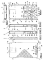
- This in Fig. 1 installation element shown has a molded body 1 made of a sound-insulating material, preferably foamed polystyrene on.
- the molded body 1 consists of a front shell 2 and a rear shell 3.
- a cistern 4 with a drain pipe (as in Fig. 16 ) built-in.
- the lower end of the drain pipe 5 protrudes at the front side 6 of the molded body 1 ( Fig. 1 ).
- the installation element off Fig. 1 for plumbing installations is attached via a mounting rail 9 to a wall and clamped over a cover plate 10.
- a mounting rail 9 to a wall and clamped over a cover plate 10.
- protruding threaded rods 11 show that serve for the cultivation of a toilet body.
- the front shell 2 has a substantially flat front side 6, which is provided with a surface profiling 12, as shown in detail in FIG Fig. 2 is shown. Apart from this surface profiling 12, the front side 6, as can be seen from the side view, substantially flat. Furthermore, in the front shell 2, an access opening 13 for later engagement of actuators in conjunction with the cistern 4 is present. At the lower end of the front shell 2 there is an outlet opening 14 for the drainage pipe 5 of the cistern 4. In addition, at the lower end two mutually spaced receiving openings 15 extend, which serve in a later described manner for fastening the installation element.
- a relatively large-volume receiving space 16 is provided for receiving the cistern 4.
- a stable rib structure 17 with a plurality of cavities 18.
- the rib structure 17 extends approximately over half the height of the front shell 2 and serves essentially to stabilize the lower region, wherein the cavities 18 reinforce the sound insulation.
- cup-shaped ribs 19 are provided which support the drain pipe 5 with built-in cistern 4. Between these cup-shaped ribs cavities 20 are also arranged.
- a plurality of locking pins 21 and plug ribs 22 are also arranged, which serve for positioning on the rear shell 3, as will be described in more detail below.
- a receiving pocket 23 is arranged, which serves for arranging further components.
- Fig. 3 It can be seen that the side surfaces 24 of the front shell 2 are also provided with a surface profiling 25.
- the rear shell 3 is shaped so that it can be fitted in register on the front shell 2 or vice versa.
- a large-volume receiving space 26 for receiving the cistern 4 is provided in the upper portion of the rear shell 3.
- On the sides of the receiving space 26 are support ribs 27, which, as in Fig. 14 can be seen, are adapted to the outer contour of the cistern 4, so that it rests on the ribs 27.
- a connection opening 28 open from the rear which is accessible from the rear side 29 of the rear shell 3.
- About the connection opening 28 is later the water supply of the cistern. 4
- the lower region of the rear shell 3 has, similar to the front shell 2, a rib structure 30 with cavities 31 for increasing the stability with good sound insulation properties. In the middle of this area are correspondingly in register with the front shell 2 ribs 32 and cavities 33 for enclosing and soundproofing of the drain pipe 5 of the cistern. 4
- plug receptacles 34 and plug-in slots 35 for receiving the plug bolts 21 and plug ribs 22 are incorporated in the region of the rib structure. Furthermore, located in the lower region of the rear shell 3, the matching halves of the receiving openings 15th
- the rear side 29 of the rear shell 3 is formed in the lower region with a shoulder 36, which serves to receive the mounting rail 9, so that the back 29 can rest flush with the wall.
- the side surfaces 37 of the rear shell 3 are also provided with a surface profiling 38, in particular with reference to FIG Fig. 9 you can see.
- Fig. 15 the closed molded body 1 with the front shell 2 and the rear shell 3 can be seen.
- Fig. 16 Cistern 4 shown installed with the drain pipe 5.
- FIGS. 17 and 18 Based on FIGS. 17 and 18 the installation of the cistern 4 can be seen in the molding 1. This rests on the support ribs 27 of the receiving space 26 of the rear shell 3. Similarly, the drain pipe 5 is located on the ribs 32nd Die Fig. 18 illustrates how after placing the front shell 2 of the cistern 4 and the drain pipe 5 is completely enclosed except for the necessary entry and exit points and clearly fixed in position.
- the rib structures 17 of the front shell 2 and 33 of the rear shell 3 abut each other and the edges of the shells 2 and 3 are equipped so that they engage in soundproofing.
- a lid 40 On the front side 39 of the cistern 4 is a lid 40 which can be removed for mounting an actuating mechanism.
- the attachment is effected by means of the fastening rail 9, which has a substantially U-shaped cross section with outwardly facing end webs 41 on the U-legs 42.
- the mounting rail 9 is above the openings 43 at the Wall attachable.
- a fastening bolt 44 On the mounting rail 9 can be pushed a fastening bolt 44, which has a tapered plug portion 45 and at its thicker end a C-shaped mounting plate 46.
- the mounting plate 46 is configured in cross-section so that it can be pushed laterally onto the mounting rail 9, but can not be removed perpendicular to the wall.
- the contour of the plug portion 45 is adapted to the inner contour of the receiving openings 15 in the molded body 1.
- the length of the plug-in portion 45, starting from the directly adjacent to this surface 47 of the mounting plate 46 to the end face 48 of the plug portion 45 is slightly less than the total thickness of the molded body 1 in the region of the receiving openings 15.
- the mounting plate 46 may be integral with the plug portion 45th be formed or made separately and attached to this.
- two threaded holes 49 and 50 are arranged in the end face 48 of the plug portion 45. These serve on the one hand to screw in the Fig. 1 shown threaded rods 11 and on the other for screwing in the fixing screws 51 (see also Fig. 1 ) for attaching the end plate 10 to the front side 6 of the molded body 1.
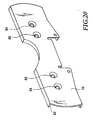
- the end plate 10 is in Fig. 20 shown.
- the end plate 10 has a collar 52 which in a groove 53 on the front shell 2 (see Fig. 2 ) in register.
- the bores 54 and 55 are each for receiving either the threaded rod 11 or the fixing screw 51, for which they are each provided with a reduction.
- a drain pipe 7 (see also Fig. 1 ) can also be attached to the molded body 1 sound-absorbing.
- the pipe clamp 8 is now fixed in the mold pocket 23.
- a screw 56 can still be used for attachment.
- the clamp 8 is made of plastic, so that a sound-insulating suspension of the drain pipe 7 is given. Based on Fig. 21 is also very easy to see how the collar 52 of the end plate 10 engages in the groove 53 in the front shell 2.
- the pipe clamp 8 is made in two parts and its lower part 8b can be attached to the upper part 8a, wherein a portion of the drain pipe 7 is encompassed form-fitting manner. By this attachment and the sound-absorbing suspension of the drain pipe 7 is brought to the molding 1.
- a fitter will prefer to do the installation after the meter break.
- 1 marks may be additionally attached to the molded body, which facilitate the alignment.
- Installation begins with the attachment of the mounting rail to the wall after the corresponding element positions and rail positions have been marked.
- the fastening bolts 44 are pushed onto the rail 9 and can be additionally fixed there by means of suitable, not shown facilities.
- the mold body 1 provided with the cistern 4 and drain pipe 5 can be pushed onto the fastening bolts 4, so that the plug-in sections 45 are located in the receiving openings 15. Due to the tapered design of both the openings 15 and the plug-in sections 45, a holding force is already achieved by the plugging operation. Now can still take place an orientation of the shaped body 1 by means of markings and subsequently the end plate 10 is placed on the front side 6. In advance, if desired, the pipe clamp 8 can still be used with the drain pipe 7 in the receiving pocket 23.
- the screws 51 are now screwed into the threaded bores 49 or 50, so that the molded body 1 is clamped between the surface 47 of the mounting plate 46 and the closure 16.
- the installation element is secured by pressing against the rail 9 or wall against moving.
- the threaded rods 11 are then screwed into the respective free threaded holes 49 or 50.
- the molded body 1 is designed over a large area and provided with a surface profiling 12, 25 and 38, this can be integrated into the wall structure. This means that immediately a plastering with mortar of the molding 1 and a subsequent tiling or masonry can take place.
- the rib structures 17 and 30 give the installation element sufficient strength, so that the attachment by means of the fastening bolts 44 is usually sufficient.
- the upper portion of the molded body 1 has sufficient strength, since it is additionally stabilized by the cistern 4. However, it is possible to fix the upper portion of the molded body 1 on the wall again.
- sound-insulating attachment means are used here.
- retaining grooves 57 may be introduced, which have a certain length and are open to the bottom of the molded body 1.
- Similar grooves may be appropriate.
- These grooves 57 can serve for pushing the molded body 1 in a wallless installation.
- a substructure may be provided on which the molded body 1 is attached. The fixation can in turn be made via the end plate 10 that the corresponding inserted into the groove 57 element fixed in this.
- the installation element according to the invention is in the assembly and in the production of great advantage. At the same time sufficient sound insulation is provided because all sound-generating parts are arranged sound-insulated in this or held on this.
- the separate preforming of half shells 2 is a significant advance in this field and results in significant cost savings.
- the self-supporting attachment can be configured in many ways. Due to the large number of possible combinations in terms of material composition, room weights, layer thicknesses and shapes in the field of plastics processing, the installation element can be given a wide variety of properties.
Landscapes
- Life Sciences & Earth Sciences (AREA)
- Engineering & Computer Science (AREA)
- Hydrology & Water Resources (AREA)
- Public Health (AREA)
- Water Supply & Treatment (AREA)
- Health & Medical Sciences (AREA)
- Sanitary Device For Flush Toilet (AREA)
- Pipe Accessories (AREA)
- Building Environments (AREA)
- Bidet-Like Cleaning Device And Other Flush Toilet Accessories (AREA)
- Paper (AREA)
- Diaphragms For Electromechanical Transducers (AREA)
- Mattresses And Other Support Structures For Chairs And Beds (AREA)
Description
- Die Erfindung betrifft ein Installationselement für Sanitärinstallationen, mit einem aus isolierendem Material bestehenden Formkörper, in dem zumindest ein Spülkasten mit Ablaufrohr angeordnet ist. Des weiteren betrifft die Erfindung einen Formkörper für ein solches Installationselement.
- Ein solcher Installationsbaustein ist aus dem deutschen Gebrauchsmuster
DE-8907973 bekannt. Bei dieser Vorrichtung sind die zur Ver- und Entsorgung eines Sanitärapparates erforderlichen Leitungen und Bauteile sowie die zur Anbringung des Sanitärapparates notwendigen Befestigungsmittel in einem geschäumten Formkörper eingelagert. Des weiteren ist zwischen Vorder- und Rückwand eine im wesentlichen über die gesamte Bausteinfläche ausgebreitete Brandschutzschicht eingeformt. Diese Schicht wird während des Herstellungsvorgangs des Formkörpers fest mit der Formkörpermasse verbunden, so daß sie Bestandteil des Formkörpers wird. Die Leitungen und Bauteile werden entsprechend bei der Umschäumung mit der Formkörpermasse gegenüber Auftrieb abgestützt. - In einem Prospekt der Firma Karl Grumbach GmbH & Co. KG, 35581 Wetzlar, ist ein WC-Baustein beschrieben, der einen PUR-Formkörper umfaßt, in den Innenteile, insbesondere ein Spülkasten, direkt eingeformt sind. Das bedeutet, daß die Innenteile von dem Kunststoff umspritzt werden. Des weiteren sind in diesem Prospekt Verkleidungsblöcke beschrieben, die an der Vorderseite eine glatte, verfließbare Fläche bereitstellen, jedoch an der Rückseite offen und in ihrem Inneren nicht an die Sanitärelemente angeformt sind. In diesem Prospekt sind auch Strangverkleidungen für Rohrleitungen gezeigt. Hierzu weisen die Verkleidungselemente Innenkonturabschnitte auf, in die Rohrleitungen einbringbar sind.
- Ein Katalogblatt der Firma Schell mit dem Druckvermerk 1/95 zeigt auf Blatt 2.3 einen Urinal-Wandeinbau-Druckspüler DN 15 VERONA. Dieser umfaßt offensichtlich eine zweiteilige Styroporummantelung. Allerdings geht aus dem Katalogblatt nicht hervor, ob die Styroporummantelung nur als Transportverpackung dient oder in die Wand eingeputzt werden soll.
- In einem Prospekt der Firma Ortwein, 73061 Ebersbach, (ohne Druckvermerk) ist eine schall- und wärmegedämmte Anschlußbox gezeigt. Diese Anschlußboxen sind hauptsächlich für den Wandeinbau vorgesehen und sind, soweit es der Prospekt erkennen läßt, einstückig, teilweise mit direkt eingeformten Rohrstücken, ausgestaltet.
- Aus dem Armaturenkatalog der Firma Hansa (Druckvermerk 95/1) ist ein Hansa-Unterputz-Universal-Einbaukörper bekannt. Dieser Einbaukörper umfaßt zwei Blockelemente, wobei das vordere Blockelement nur beim Verputzen zum Schutz der darunter liegenden Elemente Anwendung findet und anschließend entfernt wird. Ein ähnlicher Einbaukörper ist aus der
DE 3907931 C2 bekannt. - Die
DE 30 35 935 A1 befaßt sich mit einem Verbindungsstück zwischen einem Sanitärgerät und einer Wasserleitung. Dieses Verbindungsstück ist in einem Quader aus mindestens zwei ineinander schachtelbaren Teilen angeordnet, welche das Verbindungsstück mindestens teilweise formschlüssig umgeben. Die Teile bestehen aus synthetischem Hartschaum und werden mit einem Klebeband oder einem Draht oder einer Schnur zusammengehalten. Das aus den beiden Elementen gebildete Montagestück wird in einem Mauerschlitz untergebracht und dann verputzt. Ausrichthilfen für das Verputzen sind ebenfalls in dieser Druckschrift beschrieben. - In der Druckschrift
DE 26 37 719 A1 ist eine Unterputz-Armatur beschrieben, die in einer diese umgebenden Hülle aus einem Schaumstoff eingelegt ist. Die Hülle besteht aus zwei miteinander verklebten Halbschalen. Nach dem Einsetzen des hinteren Teils der Hülle in ein Mauerwerk und anschließendem Verputzen, wird der vordere Teil der Hülle zum Freilegen der Bedienelemente der Armatur entfernt. Hierdurch ist der sichtbare Teil der Armatur während des Verputzvorgangs geschützt. - Des weiteren ist aus der
EP 0480296-A1 eine Installationseinrichtung bekannt, bei der sämtliche schallerzeugenden Installationsbauteile in ein schalldämmendes Mineralfaserbett eingebaut sind. Zur Halterung der Bauteile dient eine Metallzarge, die den Montageraum umgrenzt. Die Installationsbauteile sind über schallentkoppelte Elemente mit der Metallzarge verbunden. - Ein Nachteil bei einigen dieser Vorrichtungen besteht in der relativ aufwendigen Herstellung der Installationsblöcke, da die Sanitärelemente vor dem Ausfüllen der Hohlräume mit schalldämmendem Material fixiert werden müssen. Darüber hinaus muß sichergestellt werden, daß das schalldämmende Material so eingebracht wird, daß es auch annähernd sämtliche Hohlräume erreicht und eine im wesentlichen vollständige Kapselung der schallerzeugenden Installationsbauteile bewirkt.
- Es ist die Aufgabe der vorliegenden Erfindung ein Installationselement der eingangs genannten Art bereitzustellen, das eine einfache schallisolierende Anbringung ermöglicht.
- Diese Aufgabe wird erfindungsgemäß durch die Merkmale von Anspruch 1 gelöst.
- Die vorliegende Erfindung schlägt demnach vor, den Formkörper aus mehreren Einzelteilen aufzubauen, die separat von den einzubauenden Spülkasten mit Ablaufrohr vorgefertigt werden. Die Innenkontur der Schalenelemente ist dabei auf einfache Weise so abstimmbar, daß der Spülkasten mit Ablaufrohr lediglich an entsprechender Stelle eingelegt und durch Fügen eines anderen Schalenelementes fixiert wird. Dadurch läßt sich auch eine vollständige Umschließung des Spülkastens mit Ablaufrohr erreichen. Lediglich die gewünschten Zugänge und Abgänge können durch entsprechende Öffnungen in dem Formkörper zugänglich sein. Die Erfindung bietet weiter den Vorteil, daß die Innenkontur der Schalenelemente zum Einbau von verschiedensten Spülkästen mit Ablaufrohr ausgeformt werden kann, so daß sich ein flexibles Baukastensystem ergibt. Gegebenenfalls müßten größere Abstände durch zusätzliche Einlegelemente überbrückt werden. Durch die Schalenbauweise kann eine zusätzlich Schwitzwasserisolierung, wie sie bislang im Stand der Technik üblich ist, entfallen.
- Der gesamte Spülkasten läßt sich durch den Formkörper hervorragend schallisolieren, ohne daß es größere Probleme bei der Herstellung des Installationsbausteins im Gegensatz zum Stand der Technik gibt. Zum Beispiel muß ein Fixieren des Spülkastens gegen Auftrieb, wie teilweise im Stand der Technik, nicht vorgesehen sein.
- Der Formkörper wird aus einem aus zwei Halbschalen bestehenden Kasten bereit gestellt. Durch die Reduktion auf lediglich zwei Halbschalen ergibt sich eine starke Vereinfachung des Formkörpers, auch hinsichtlich des Zusammenfügens des Installationsbausteins. Hierbei wird der Spülkasten mit Ablaufrohr in eine der beiden Halbschalen eingelegt und durch Aufsetzen der anderen Halbschale umschlossen und fixiert.
- Die Teilungsebene der beiden Halbschalen verläuft parallel zur Vorder- und Rückseite des Formkörpers. Hierdurch läßt sich auch sehr einfach eine dichte Fügung der beiden Halbschalen erreichen.
- Der Formkörper weist im Abstand zu dem schallzudämmenden Spülkasten mit Ablaufrohr Aufnahmeöffnungen auf. Des weiteren sind Befestigungsmittel vorgesehen, die zum Einführen in die Aufnahmeöffnungen, insbesondere für die Wandmontage, dienen. Eine derartige Ausbildung läßt eine sehr einfache Anordnung des Installationselementes zu. Die Befestigungsmittel werden an der dafür vorgesehenen Stelle befestigt und der Formkörper aufgeschoben. Der Formkörper übernimmt somit die Trag- bzw. Stütz- und Anordnungsfunktion für den Spülkasten mit Ablaufrohr. Weitere Befestigungselemente, die ggf. schallentkoppelt werden müssen, brauchen nicht vorgesehen sein. Da die Aufnahmeöffnungen von schalldämmendem Werkstoff geformt sind, ist automatisch eine schallisolierende Anbringung des Installationselements herbeigeführt.
- Bei einer Variante sind die Schalenelemente über reibschlüssig ineinandergreifende Steck- und Aufnahmeelemente miteinander, insbesondere wasserdicht, verbunden. Diese einfache Verbindungsmethode läßt sich formtechnisch sehr einfach realisieren und sorgt für ein paßgenaues Aneinanderstecken. Die Steck- und Aufnahmeelemente können darüber hinaus so ausgeführt sein, daß sie auch unlösbar und/oder wasserdicht verbindbar sind.
- Des weiteren kann der Formkörper an mindestens zwei unterschiedlichen Bereichen mit unterschiedlichen Raumgewichten bzw. Dämmeigenschaften ausgebildet sein. Durch den Übergang von verschiedenen Raumgewichten ist eine Pufferwirkung erzielt, die zusätzlich die Dämmeigenschaften verbessert. Die Anordnung von Bereichen von unterschiedlichen Raumgewichten kann so erfolgen, daß eine stabile Tragstruktur für den Spülkasten mit Ablaufrohr im Formkörper gegeben ist und sämtliche anderen Bereiche mit Material niedrigen Raumgewichtes ausgefüllt sind. Hierdurch wird die schalldämmende Wirkung des Formkörpers optimiert.
- Bevorzugt kann der Formkörper mehrschichtig aufgebaut sein. Die einzelnen Schichten können sich aufgrund von speziellen Erfordernissen ergeben. Zum Beispiel kann eine Brandschutzschicht vorgesehen sein.
- Günstigerweise können die Schichten oder Bereiche unterschiedliche Eigenschaften, wie z.B. Dichte, Festigkeit, Schalldämmung oder Brandschutz aufweisen.
- Wenn zumindest die Vorderseite des Formkörpers im wesentlichen vollständig als großflächige Montagefläche, insbesondere putz- und verfliesungsfähige Fläche, ausgebildet und mit einer Oberflächenprofilierung versehen ist, kann diese zum Aufbringen von Putz und anschließender Verfliesung verwendet werden. Selbstverständlich können die Rückseite und die Seitenflächen ähnlich ausgebildet sein, um entsprechend mit Wandbauten verbunden zu werden. Die entsprechende Ausgestaltung der Oberfläche des Formkörpers macht ein entsprechendes Bereitstellen von Zusatzbauelementen, wie z.B. Streckmetall, zur Anhaftung von Mörtel nicht mehr notwendig.
- Bevorzugt kann zumindest der Bereich um die Aufnahmeöffnungen des Formkörpers ausreichend stabil ausgebildet sein, um einen selbsttragenden Formkörper bereitzustellen, ohne daß zusätzliche Befestigungsmittel für den Spülkasten mit Ablaufrohr notwendig sind.
- Bevorzugterweise können sich die Aufnahmeöffnungen von der Rückseite zur Vorderseite des Formkörpers durch die entsprechenden Schalenelemente hindurch erstrecken und die Befestigungsmittel an ihrer an der Vorderseite zugänglichen Stirnseite Befestigungseinrichtungen, insbesondere mindestens eine Gewindebohrung, aufweisen, durch die von außen kommende Belastungskräfte im wesentlichen von den Befestsigungsmitteln aufnehmbar sind. Somit kann das Befestigungsmittel durch geeignete Befestigungseinrichtungen gegenüber dem Formkörper arretiert werden oder es besteht die Möglichkeit, weitere Anbauteile an den Befestigungsmitteln anzubringen, die keine Belastungen auf den Formkörper ausüben, da diese am Formkörper vorbeigeleitet werden. Zum Beispiel könnte ein WC-Körper an die Befestigungsmittel angeschraubt werden. Die Anordnung der Befestigungsmittel und die Anzahl der Befestigungseinrichtungen richtet sich dann nach der Art der anzubringenden Zusatzbauelemente. Es können Befestigungseinrichtungen der verschiedensten Anordnung und mit unterschiedlichen Abständen vorgesehen sein, so daß ganze Baureihen von Anbauelementen mit den Befestigungsmitteln verbindbar sind.
- Eine sehr gute Fixierung des Formkörpers auf den Befestigungsbolzen kann dadurch erreicht werden, daß die Aufnahmeöffnungen sich von der Rückseite zur Vorderseite des Formkörpers verjüngen und als Befestigungsmittel Befestigungsbolzen vorgesehen sind, die entsprechend in der Außenkontur angepaßt sind. Da sich die Aufnahmeöffnungen durch mindestens zwei Schalenelemente hindurch erstrecken, werden diese hierdurch noch zusätzlich zentriert. Diese Ausgestaltung bietet auch eine Montageerleichterung, da die Befestigungsbolzen immer mit leichtem Haftsitz in den Aufnahmeöffnungen sitzen, und darüber hinaus auch kein seitenverkehrtes Anbringen des Formkörpers an Befestigungsbolzen möglich ist.
- In vorteilhafter Weise können die Befestigungsmittel eine Anschlagfläche zur Anlage an einen Rückseitenbereich des Formkörpers aufweisen, und ein Abschlußblech kann zum Verbinden mit der Stirnseite der Befestigungsmittel vorgesehen sein, das mit der Vorderseite des Formkörpers zur Anlage kommt, so daß dieser zwischen den Anschlagflächen an den Befestigungsmittel und dem Abschlußblech eingespannt ist. Das Abschlußblech sorgt für eine großflächige Anlage am Formkörper und für eine gute Kraftverteilung der Festklemmkraft über die Andrückfläche. Dadurch läßt sich selbst ein Formkörper aus relativ weichem Werkstoff sehr gut befestigen. Das Abschlußblech kann auch zur Anordnung weiterer Bauteile verwendet werden. Es können auch mehrere Abschlußbleche verwendet werden.
- Darüber hinaus kann eine Befestigungsschiene vorgesehen sein, und die Befestigungsmittel können Führungseinrichtungen zum seitlichen Aufschieben oder Aufstecken auf die Befestigungsschiene aufweisen. Ein Halten in Belastungsrichtung an der Befestigungsschiene ist ebenfalls verwirklicht. Durch diese Maßnahme wird die Montage des Installationsbausteins nochmals erleichtert. Durch ein verschiebliches Anordnen der Befestigungsmittel auf einer Schiene können diese in unterschiedlichen Abständen angebracht werden, wie es für unterschiedliche Anwendungszwecke erforderlich ist. Darüber hinaus ist auch eine Reihenanordnung an einer längeren Befestigungsschiene möglich. Es ist bei einer solchen Ausgestaltung noch nicht einmal nötig, die Befestigungsmittel von dem Formkörper zu lösen, um diesen seitlich an der Befestigungsschiene zu verschieben. Des weiteren ist ein Aufschieben, Aufstecken und/oder Aufschrauben bei der Montage auch ohne eine Schiene möglich.
- Günstigerweise können Arretiereinrichtungen zum Arretieren der Befestigungsmittel an der Befestigungssschiene vorgesehen sein. Bevorzugt sind diese im Element integriert.
- Kostengünstig, bei ausreichender Festigkeit und ausreichenden Schalldämmeigenschaften, ist der Formkörper aus geschäumtem Kunststoff, insbesondere Polystyrol, herzustellen.
- Bei entsprechender Anordnung der Trennebenen der Schalenelemente lassen sich diese sämtlich ohne Hinterschneidungen herstellen, so daß sich einfachste Werkzeugformen ergeben.
- Damit möglichst wenig Körperschall von den im Formkörper eingebauten Sanitärelementen auf den Formkörper übertragen wird, sind im Inneren des Formkörpers Rippenelemente angeordnet, die im wesentlichen paßgenau bereichsweise an den Sanitärelementen anliegen und diese fixieren. Damit ist die Berührungsfläche zwischen den Sanitärelementen und dem Formkörper minimiert. Zusätzlich dienen die zwischen den einzelnen Rippenelementen gebildeten Hohlräume innerhalb des Formkörpers zusätzlich zur Schallisolierung.
- Um zusätzliche Bauelemente an dem Formkörper anzubringen, können zumindest auf der Vorder- und/oder Rückseite des Formkörpers Formtaschen zur Aufnahme und/oder Anbringung zusätzlicher Sanitärelemente und/oder Befestigungs- bzw. Aufstelleinrichtungen vorgesehen sein. Die Bauelemente können z.B. formgenau in diese Formtaschen eingelegt und z.B. über das Abdeckblech mit Hilfe der Befestigungsbolzen arretiert werden. Des weiteren können solche Formtaschen dazu dienen, den gesamten Formkörper auf ein Trägergestell aufzuschieben und diesen so zu haltern. Dadurch ist z.B. eine Aufstellung frei im Raum unter Verwendung eines Sockelgestells möglich.
- Des weiteren kann eine Rohrschelle, ein Abflußrohr und eine Formtasche zum Anbringen der Rohrschelle vorgesehen sein, wobei das Abflußrohr schallgedämmt angebracht ist. Die Rohrschelle wird zumindest bereichsweise in eine Formtasche am Formkörper eingesetzt und dort gehalten, ggf. durch das Abschlußblech. Hierdurch ergibt sich automatisch eine schallgedämmte Anbringung auch des Abflußrohres, so daß auch keine zusätzliche schallgedämmte Befestigung für dieses vorgesehen sein muß.
- Zur verbesserten Montage kann weiterhin vorgesehen sein, daß auf der Außenseite des Formkörpers Montagemarkierungen angeformt sind. Somit läßt sich dieser exakt ausrichten bei der Anbringung.
- Darüber hinaus können im Bereich der Formtaschen und/oder Befestigungsbereiche des Formkörpers verformbare Vorsprünge vorgesehen sein, die ein stufenweises Verspannen zum Verstellen im vormontierten Zustand ermöglichen. Diese Vorsprünge dienen der Montageerleichterung und werden nach dem Ausrichten verformt beziehungsweise zerstört.
- Zum Erhöhen der Stabilität kann ein Befestigungsmittel (oder mehrere) zum Anbringen am oberen Randbereich des Formkörpers und zur Wandverbindung vorgesehen sein.
- Im folgenden werden Ausführungsbeispiele der vorliegenden Erfindung anhand einer Zeichnung näher erläutert. Es zeigt:
- Fig. 1
- eine schematische perspektivische Darstellung eines Installationselements für Sanitärinstallationen gemäß der vorliegenden Erfindung,
- Fig. 2
- eine Vorderansicht einer Vorderschale einer erfindungsgemäßen Ausführungsform eines Formkörpers,
- Fig. 3
- eine Seitenansicht der Vorderschale aus
Fig. 2 , - Fig. 4
- die Vorderschale aus
Fig. 2 entlang der Linie IV-IV geschnitten, - Fig. 5
- die Vorderschale aus
Fig. 2 entlang der Linie V-V geschnitten, - Fig. 6
- eine Rückansicht der Vorderschale aus
Fig. 2 , - Fig. 7
- die Vorderschale aus
Fig. 6 entlang der Linie VII-VII geschnitten, - Fig. 8
- eine Vorderansicht der Hinterschale für eine Ausführungsform eines Formkörpers gemäß der vorliegenden Erfindung,
- Fig. 9
- eine Seitenansicht der Hinterschale aus
Fig. 8 , - Fig. 10
- die Hinterschale aus
Fig. 8 entlang der Linie X-X geschnitten, - Fig. 11
- ein Ausschnitt der Hinterschale aus
Fig. 8 entlang der Linie XI-XI geschnitten, - Fig. 12
- eine Rückansicht der Hinterschale aus
Fig. 8 , - Fig. 13
- eine Draufsicht der Hinterschale aus
Fig. 12 , - Fig. 14
- die Hinterschale aus
Fig. 8 entlang der Linie XIV-XIV geschnitten, - Fig. 15
- den zusammengesetzten Formkörper mit den Halbschalen aus
Fig. 2 undFig. 8 in einer Seitenansicht, - Fig. 16
- einen Spülkasten mit Ablaufrohr zum Einbau in den Formkörper aus
Fig. 15 , - Fig. 17
- die Hinterschale aus
Fig. 8 mit eingelegtem Spülkasten ausFig. 16 , - Fig. 18
- ein Installationselement unter Verwendung der Bauelemente aus
Fig. 17 und der Vorderschale ausFig. 2 in einer geschnittenen Seitenansicht, - Fig. 19
- einen Befestigungsbolzen mit Befestigungsschiene in einer perspektivischen Darstellung,
- Fig. 20
- ein Abschlußblech in perspektivischer Darstellung und
- Fig. 21
- eine Anbringungsmöglichkeit eines Abflußrohres an die untere Kante des Formkörpers in einer teilweisen Schnittdarstellung.
- Das in
Fig. 1 dargestellte Installationselement weist einen Formkörper 1 aus einem schalldämmenden Werkstoff, bevorzugt geschäumtes Polystyrol, auf. Der Formkörper 1 besteht aus einer Vorderschale 2 und einer Hinterschale 3. In dem Formkörper 1 ist ein Spülkasten 4 mit einem Ablaufrohr (wie inFig. 16 ) eingebaut. Das untere Ende des Ablaufrohres 5 schaut an der Vorderseite 6 des Formkörpers 1 hervor (Fig. 1 ). - Wie im folgenden noch näher beschrieben wird, ist am unteren Ende des Formkörpers 1 noch ein Winkelstück eines Abflußrohres 7 mittels einer Rohrschelle 8 angebracht.
- Das Installationselement aus
Fig. 1 für Sanitärinstallationen wird über eine Befestigungsschiene 9 an einer Wand befestigt und über ein Abschlußblech 10 geklemmt. An der Vorderseite 6 stehen zusätzlich über das Abschlußblech 10 hinausragende Gewindestangen 11 hervor, die zum Anbau eines WC-Körpers dienen. - Anhand der
Fig. 2 bis 7 wird nun der Aufbau einer ähnlichen Vorderschale 2, wie inFig. 1 , näher erläutert. - Die Vorderschale 2 weist eine im wesentlichen ebene Vorderseite 6 auf, die mit einer Oberflächenprofilierung 12 versehen ist, wie sie ausschnittsweise in
Fig. 2 dargestellt ist. Abgesehen von dieser Oberflächenprofilierung 12 ist die Vorderseite 6, wie anhand der Seitenansicht zu sehen ist, im wesentlichen eben. Des weiteren ist in der Vorderschale 2 eine Zugriffsöffnung 13 zum späteren Eingriff von Betätigungselementen in Verbindung mit dem Spülkasten 4 vorhanden. Am unteren Ende der Vorderschale 2 befindet sich eine Ausgangsöffnung 14 für das Ablaufrohr 5 des Spülkastens 4. Darüber hinaus erstrecken sich am unteren Ende zwei im Abstand zueinander angeordnete Aufnahmeöffnungen 15, die in noch später beschriebener Weise zur Befestigung des Installationselement dienen. - Betrachtet man nunmehr die Rückseite der Vorderschale 2 (
Fig. 6 ) so erkennt man in Verbindung mit den Schnittdarstellungen ausFig. 4 und 5 , das ein relativ großvolumiger Aufnahmeraum 16 zur Aufnahme des Spülkastens 4 vorgesehen ist. Unterhalb dieses Aufnahmeraumes 16 befindet sich eine stabile Rippenstruktur 17 mit mehreren Hohlräumen 18. Die Rippenstruktur 17 erstreckt sich annähernd über die halbe Höhe der Vorderschale 2 und dient im wesentlichen zur Stabilisierung des unteren Bereiches, wobei die Hohlräume 18 die Schalldämmung noch verstärken. In der Mitte der Rippenstruktur 17 sind schalenförmige Rippen 19 vorgesehen, die bei eingebautem Spülkasten 4 das Ablaufrohr 5 abstützen. Zwischen diesen schalenförmigen Rippen sind ebenfalls Hohlräume 20 angeordnet. - Auf der Innenseite der Vorderschale 2 sind darüber hinaus mehrere Steckbolzen 21 und Steckrippen 22 angeordnet, die zur Positionierung an der Hinterschale 3 dienen, wie im folgenden noch näher beschrieben wird.
- Aus der
Fig. 2 in Verbindung mit derFig. 4 ist zu erkennen, daß am unteren Rand der Vorderschale 2 eine Aufnahmetasche 23 angeordnet ist, die zum Anordnen weiterer Bauelemente dient. - Anhand der
Fig. 3 ist zu erkennen, daß die Seitenflächen 24 der Vorderschale 2 ebenfalls mit einer Oberflächenprofilierung 25 versehen sind. - Anhand der
Fig. 8 bis 14 wird nun im folgenden der Aufbau der Hinterschale 3 beschrieben. - Die Hinterschale 3 ist so geformt, daß sie paßgenau auf die Vorderschale 2 aufgesteckt werden kann oder umgekehrt.
- Im oberen Abschnitt der Hinterschale 3 ist ein großvolumiger Aufnahmeraum 26 zur Aufnahme des Spülkastens 4 vorgesehen. An den Seiten des Aufnahmeraumes 26 befinden sich Auflagerippen 27, die, wie in
Fig. 14 zu sehen ist, an die Außenkontur des Spülkastens 4 angepaßt sind, damit dieser auf den Rippen 27 aufliegt. Des weiteren befindet sich im oberen Bereich des Aufnahmeraumes 26 ein von hinten offener Anschlußdurchbruch 28, der von der Rückseite 29 der Hinterschale 3 her zugänglich ist. Über den Anschlußdurchbruch 28 erfolgt später die Wasserversorgung des Spülkastens 4. - Der untere Bereich der Hinterschale 3 weist ähnlich der Vorderschale 2 eine Rippenstruktur 30 mit Hohlräumen 31 zur Erhöhung der Stabilität bei guten Schalldämmeigenschaften auf. In der Mitte dieses Bereiches befinden sich entsprechend paßgenau zur Vorderschale 2 Rippen 32 und Hohlräume 33 zum Umschließen und Schallisolieren des Ablaufrohres 5 des Spülkastens 4.
- Für die paßgenaue Steckverbindung zwischen Vorderschale 2 und Hinterschale 3 sind im Bereich der Rippenstruktur 30 Steckaufnahmen 34 und Steckschlitze 35 zur Aufnahme der Steckbolzen 21 und Steckrippen 22 eingearbeitet. Des weiteren befinden sich im unteren Bereich der Hinterschale 3 die passenden Hälften der Aufnahmeöffnungen 15.
- Die Rückseite 29 der Hinterschale 3 ist im unteren Bereich mit einem Absatz 36 ausgebildet, der zur Aufnahme der Befestigungsschiene 9 dient, damit die Rückseite 29 wandbündig anliegen kann.
- Die Seitenflächen 37 der Hinterschale 3 sind ebenfalls mit einer Oberflächenprofilierung 38 versehen, wie insbesondere anhand der
Fig. 9 zu sehen ist. - In
Fig. 15 ist der geschlossene Formkörper 1 mit der Vorderschale 2 und der Hinterschale 3 zu sehen. In diesen Formkörper 1 ist der inFig. 16 gezeigte Spülkasten 4 mit dem Ablaufrohr 5 eingebaut. - Anhand der
Fig. 17 und 18 ist der Einbau des Spülkastens 4 in den Formkörper 1 zu erkennen. Dieser liegt auf den Auflagerippen 27 des Aufnahmeraums 26 der Hinterschale 3 auf. Ebenso befindet das Ablaufrohr 5 auf den Rippen 32. DieFig. 18 verdeutlicht, wie nach Aufsetzen der Vorderschale 2 der Spülkasten 4 und das Ablaufrohr 5 bis auf die notwendigen Zu- und Abgangsstellen vollständig umschlossen und eindeutig in der Lage fixiert ist. Die Rippenstrukturen 17 der Vorderschale 2 und 33 der Hinterschale 3 liegen aneinander an und die Ränder der Schalen 2 und 3 sind so ausgestattet, daß sie schalldichtend ineinandergreifen. - Auf der Vorderseite 39 des Spülkastens 4 befindet sich ein Deckel 40, der zum Anbau eines Betätigungsmechanismuses entfernt werden kann.
- Anhand der
Fig. 19 wird nun die Befestigungsmöglichkeit des Formkörpers 1 an einer Wandfläche erläutert. - Die Befestigung erfolgt mittels der Befestigungsschiene 9, die im wesentlichen einen U-förmigen Querschnitt mit nach außen weisenden Endstegen 41 an den U-Schenkeln 42 aufweist. Die Befestigungsschiene 9 ist über die Öffnungen 43 an der Wand anbringbar.
- Auf die Befestigungsschiene 9 aufschiebbar ist ein Befestigungsbolzen 44, der einen sich verjüngenden Steckabschnitt 45 und an seinem dickeren Ende eine C-förmige Befestigungsplatte 46 aufweist. Die Befestigungsplatte 46 ist im Querschnitt so ausgestaltet, daß sie seitlich auf die Befestigungsschiene 9 aufschiebbar ist, jedoch nicht senkrecht zur Wand abgenommen werden kann.
- Die Kontur des Steckabschnittes 45 ist an die Innenkontur der Aufnahmeöffnungen 15 im Formkörper 1 angepaßt. Die Länge des Steckabschnittes 45, ausgehend von der direkt an diesen angrenzenden Fläche 47 der Befestigungsplatte 46 bis zur Stirnfläche 48 des Steckabschnittes 45, ist etwas geringer als die Gesamtdicke des Formkörpers 1 im Bereich der Aufnahmeöffnungen 15. Die Befestigungsplatte 46 kann einteilig mit dem Steckabschnitt 45 ausgebildet sein oder separat hergestellt und an dieser befestigt werden. In der Stirnfläche 48 des Steckabschnittes 45 sind zwei Gewindebohrungen 49 und 50 angeordnet. Diese dienen zum einen zum Einschrauben der in
Fig. 1 gezeigten Gewindestangen 11 und zum anderen zum Einschrauben der Befestigungsschrauben 51 (siehe ebenfallsFig. 1 ) zum Befestigen des Abschlußbleches 10 an der Vorderseite 6 des Formkörpers 1. - Das Abschlußblech 10 ist in
Fig. 20 dargestellt. Das Abschlußblech 10 weist einen Kragen 52 auf, der in eine Nut 53 an der Vorderschale 2 (sieheFig. 2 ) paßgenau eingreift. Die Bohrungen 54 und 55 dienen jeweils zur Aufnahme entweder der Gewindestange 11 oder der Befestigungsschraube 51, wofür diese jeweils mit einer Senkung versehen sind. - Anhand der Lochabstände der Bohrungen 54 und 55 ist zu erkennen, daß zwei Anbringungsmöglichkeiten in bezug auf die Mitte des Formkörpers 1 gegeben sind. Demnach lassen sich Anbauteile mit eben diesen verschiedenen Lochabständen anbringen.
- Mittels der
Fig. 21 ist nunmehr dargestellt, wie ein Abflußrohr 7 (siehe auchFig. 1 ) ebenfalls an dem Formkörper 1 schalldämmend angebracht werden kann. Hierzu weist die Vorderschale 2 auf ihrer Vorderseite 6 die Aufnahmetasche 23 auf, in die ein entsprechend ausgeformter Abschnitt der Rohrschelle 8 paßgenau einlegbar ist und bündig mit der Vorderseite 6 der Vorderschale 2 abschließt. Durch Anschrauben des Abschlußbleches 10 wird nun die Rohrschelle 8 in der Formtasche 23 fixiert. Zusätzlich kann noch eine Schraube 56 zur Befestigung verwendet werden. Die Rohrschelle 8 ist aus Kunststoff hergestellt, so daß eine schallisolierende Aufhängung des Abflußrohres 7 gegeben ist. Anhand derFig. 21 ist auch sehr gut zu erkennen, wie der Kragen 52 des Abschlußbleches 10 in die Nut 53 in der Vorderschale 2 eingreift. Die Rohrschelle 8 ist zweiteilig ausgeführt und ihr unterer Teil 8b läßt sich an den oberen Teil 8a aufstecken, wobei ein Bereich des Abflußrohres 7 formschlüssig umgriffen wird. Durch diese Befestigung wird auch die schalldämmende Aufhängung des Abflußrohres 7 an dem Formkörper 1 herbeigeführt. - Im folgenden wird die Wirkungs- und Funktionsweise des beschriebenen Ausführungsbeispiels näher erläutert.
- Ein Monteur wird bevorzugt nach dem Meterriß die Installation vornehmen. Hierzu können zusätzlich am Formkörper 1 Markierungen angebracht sein, die die Ausrichtung erleichtern.
- Die Montage beginnt mit der Befestigung der Befestigungsschiene an der Wand, nachdem die entsprechenden Elementpositionen und Schienenpositionen angezeichnet worden sind.
- Anschließend werden die Befestigungsbolzen 44 auf die Schiene 9 aufgeschoben und können dort mittels geeigneter, nicht dargestellter Einrichtungen zusätzlich fixiert werden. Anschließend kann der mit dem Spülkasten 4 und Ablaufrohr 5 versehene Formkörper 1 auf die Befestigungsbolzen 4 aufgeschoben werden, so daß sich die Steckabschnitte 45 in den Aufnahmeöffnungen 15 befinden. Durch die verjüngende Ausbildung sowohl der Öffnungen 15 als auch der Steckabschnitte 45 ist bereits eine Haltekraft durch den Steckvorgang erreicht. Nun kann noch eine Ausrichtung des Formkörpers 1 anhand von Markierungen stattfinden und nachfolgend wird das Abschlußblech 10 auf die Vorderseite 6 aufgesetzt. Vorab kann, falls gewünscht, noch die Rohrschelle 8 mit dem Abflußrohr 7 in die Aufnahmetasche 23 eingesetzt werden. Abhängig vom Lochabstand des später zu befestigenden WC-Körpers werden nun die Schrauben 51 in die Gewindebohrungen 49 oder 50 eingeschraubt, so daß der Formkörper 1 zwischen der Fläche 47 der Befestigungsplatte 46 und dem Abschluß 16 festgeklemmt wird. Gleichzeitig wird das Installationselement durch Andrücken an die Schiene 9 oder Wand gegen Verschieben gesichert. Die Gewindestangen 11 werden dann in die jeweils freien Gewindebohrungen 49 oder 50 eingeschraubt.
- Dadurch, daß der Formkörper 1 großflächig ausgestaltet und mit einer Oberflächenprofilierung 12, 25 und 38 versehen ist, kann dieser in den Wandaufbau integriert werden. Das bedeutet, daß unmittelbar eine Verputzung mit Mörtel des Formkörpers 1 und eine anschließende Verfliesung oder Vermauerung stattfinden kann. Die Rippenstrukturen 17 und 30 verleihen dabei dem Installationselement eine ausreichende Festigkeit, so daß die Anbringung mittels der Befestigungsbolzen 44 in aller Regel ausreichend ist. Auch der obere Bereich des Formkörpers 1 weist eine ausreichende Festigkeit auf, da dieser zusätzlich vom Spülkasten 4 stabilisiert wird. Jedoch besteht die Möglichkeit, auch den oberen Abschnitt des Formkörpers 1 an der Wand nochmals zu fixieren. Bevorzugt werden hier schallisolierende Anbringungsmittel verwendet.
- Nach dem Verfliesen kann die Befestigung des WC-Körpers vorgenommen werden.
- Anhand der
Fig. 1 ist noch zu erkennen, daß zusätzlich in der Vorderseite 6 der Vorderschale 2 Haltenuten 57 eingebracht sein können, die eine bestimmte Länge aufweisen und zum Boden des Formkörpers 1 hin offen sind. Auf der Rückseite der Hinterschale 3 können ähnliche Nuten angebracht sein. Diese Nuten 57 können zum Aufschieben des Formkörpers 1 bei wandloser Aufstellung dienen. Zum Beispiel kann eine Unterkonstruktion vorgesehen sein, auf das der Formkörper 1 aufgesteckt ist. Die Fixierung kann wiederum über das Abschlußblech 10 erfolgen, daß das entsprechende in die Nut 57 eingeschobene Element in dieser fixiert. - Das erfindungsgemäße Installationselement ist in der Montage und in der Herstellung von großem Vorteil. Gleichzeitig wird eine ausreichende Schallisolierung bereitgestellt, da sämtliche schallerzeugende Teile schallgedämmt in diesem angeordnet oder an diesem gehalten sind. Das separate Vorformen von Halbschalen 2 ist ein entscheidender Fortschritt auf diesem Gebiet und hat erhebliche Kosteneinsparungen zur Folge.
- Die selbsttragende Anbringung kann vielfältig ausgestaltet sein. Aufgrund der großen Anzahl an Kombinationsmöglichkeiten bezüglich Materialzusammensetzung, Raumgewichte, Schichtdicken und Formgebungen auf dem Gebiet der Kunststoffverarbeitung können dem Installationselement die unterschiedlichsten Eigenschaften verliehen werden.
Claims (19)
- Installationselement für Sanitärinstallationen mit einem aus isolierendem Material bestehenden Formkörper (1), in dem zumindest ein Spülkasten (4) mit Ablaufrohr (5) angeordnet ist, dadurch gekennzeichnet, dass der Formkörper (1) aus einem aus zwei Halbschalen (2,3) bestehenden Kasten gebildet ist, dass die Halbschalen (2,3) an die Kontur des Spülkastens (4) mit Ablaufrohr (5) angepasst, schalldämmend geformt und im wesentlichen passgenau miteinander zum entsprechenden Aufnehmen und Umschließen des Spülkastens (4) mit Ablaufrohr (5) fügbar sind, dass die Teilungsebene der beiden Halbschalen (2,3) parallel zur Vorder- bzw. Rückseite des Formkörpers (1) verläuft, dass der Formkörper (1) im Abstand zu dem schallzudämmenden Spülkasten (4) mit Ablaufrohr (5) Aufnahmeöffnungen (15) aufweist und dass Befestigungsmittel (44) vorgesehen sind, die zum Einführen in die Aufnahmeöffnung (15), insbesondere für die Wandmontage, dienen.
- Installationselement nach Anspruch 1, dadurch gekennzeichnet, dass die Schalenelemente (2,3) über reibschlüssig ineinandergreifende Steck- und Aufnahmeelemente (21,22; 34.35) miteinander, insbesondere wasserdicht, verbunden sind.
- Installationselement nach einem der Ansprüche 1 oder 2, dadurch gekennzeichnet, dass der Formkörper (1) an mindestens zwei unterschiedlichen Bereichen mit unterschiedlichen Raumgewichten bzw. Dämmeigenschaften ausgebildet ist.
- Installationselement nach einem der Ansprüche 1 bis 3, dadurch gekennzeichnet, dass der Formkörper (1) mehrschichtig aufgebaut ist.
- Installationselement nach Anspruch 3 oder 4, dadurch gekennzeichnet, dass die Schichten oder Bereiche unterschiedliche Eigenschaften, wie z.B. Dichte, Festigkeit, Schalldämmung oder Brandschutz aufweisen.
- Installationselement nach einem der Ansprüche 1 bis 5, dadurch gekennzeichnet, dass zumindest die Vorderseite (6) des Formkörpers (1) im wesentlichen vollständig als großflächige Montagefläche, insbesondere putz- und verfliesungsfähige Fläche, ausgebildet und mit einer Oberflächenprofilierung (12) versehen ist.
- Installationselement nach einem der Ansprüche 1 bis 6, dadurch gekennzeichnet, dass zumindest der Bereich um die Aufnahmeöffnungen (15) des Formkörpers (1) ausreichend stabil ausgebildet ist, um einen selbsttragenden Formkörper (1) bereitzustellen.
- Installationselement nach Anspruch 7, dadurch gekennzeichnet, dass sich die Aufnahmeöffnungen (15) von der Rückseite zur Vorderseite des Formkörpers (1) durch die entsprechenden Schalenelemente (2,3) hindurch erstrecken und die Befestigungsmittel (44) an ihrer von der Vorderseite zugänglichen Stirnseite (48) Befestigungseinrichtungen (49,50), insbesondere mindestens eine Gewindebohrung, aufweisen, durch die von außen kommende Belastungskräfte im wesentlichen von den Befestigungsmitteln (44) aufnehmbar sind.
- Installationselement nach einem der Ansprüche 1 bis 8, dadurch gekennzeichnet, dass die Aufnahmeöffnungen (15) sich von der Rückseite zur Vorderseite des Formkörpers (1) verjüngen und als Befestigungsmittel Befestigungsbolzen (44) vorgesehen sind, die entsprechend in der Außenkontur angepasst sind.
- Installationselement nach einem der Ansprüche 1 bis 9, dadurch gekennzeichnet, dass die Befestigungsmittel (44) eine Anschlagfläche (47) zur Anlage an einen Rückseitenbereich des Formkörpers (1) aufweisen und das ein Abschlussblech (10) zum Verbinden mit der Stirnseite (48) der Befestigungsmittel (44) vorgesehen ist, das mit der Vorderseite des Formkörpers (1) zur Anlage kommt, so dass dieser zwischen den Anschlagflächen (47) an den Befestigungsmittel (44) und dem Abschlussblech (10) eingespannt ist.
- Installationselement nach einem der Ansprüche 1 bis 10, dadurch gekennzeichnet, dass eine Befestigungsschiene (9) vorgesehen ist, und die Befestigungsmittel (44) Führungseinrichtungen (46) zum seitlichen Aufschieben oder Aufstecken auf die und Halten in Belastungsrichtung der Befestigungsschiene (9) aufweist.
- Installationselement nach Anspruch 11, dadurch gekennzeichnet, dass Arretiereinrichtungen zum Arretieren der Befestigungsmittel (44) an der Befestigungsschiene (9) vorgesehen sind.
- Installationselement nach einem der Ansprüche 1 bis 12, dadurch gekennzeichnet, dass der Formkörper (1) aus geschäumtem Kunststoff, insbesondere Polystyrol, besteht.
- Installationselement nach einem der Ansprüche 1 oder 13, dadurch gekennzeichnet, dass im Inneren des Formkörpers (1) Rippenelemente (19,27,32) angeordnet sind, die im wesentlichen passgenau bereichsweise an dem Spülkasten (4) mit Ablaufrohr (5) anliegen und diesen fixieren.
- Installationselement nach einem der Ansprüche 1 bis 14, dadurch gekennzeichnet, dass zumindest auf der Vorder- und/oder Rückseite des Formkörpers (1) Formtaschen (23) zur Aufnahme und/oder Anbringung zusätzlicher Sanitärelemente (7) und/oder Befestigungs- bzw. Aufstelleinrichtungen (8) vorgesehen sind.
- Installationselement nach Anspruch 15, dadurch gekennzeichnet, dass eine Rohrschelle (8), ein Abflussrohr (7) und eine Formtasche (21) zum Anbringen der Rohrschelle (8) vorgesehen sind, wobei das Abflussrohr (7) schallgedämmt angebracht ist.
- Installationselement nach einem der Ansprüche 1 bis 16, dadurch gekennzeichnet, dass auf der Außenseite des Formkörpers (1) Montagemarkierungen angeformt sind.
- Installationselement nach einem der Ansprüche 15 bis 16, dadurch gekennzeichnet, dass im Bereich der Formtaschen (23) und/oder der Befestigungsbereiche des Formkörpers (1) verformbare Vorsprünge vorgesehen sind, die ein stufenweises Verspannen zum Verstellen im vormontierten Zustand ermöglichen.
- Installationselement nach einem der Ansprüche 1 bis 18, dadurch gekennzeichnet, dass ein Befestigungsmittel zum Anbringen am oberen Randbereich des Formkörpers (1) vorgesehen ist.
Applications Claiming Priority (2)
| Application Number | Priority Date | Filing Date | Title |
|---|---|---|---|
| DE19635759 | 1996-09-03 | ||
| DE19635759A DE19635759A1 (de) | 1996-09-03 | 1996-09-03 | Installationselement für Sanitärinstallationen |
Publications (3)
| Publication Number | Publication Date |
|---|---|
| EP0826837A1 EP0826837A1 (de) | 1998-03-04 |
| EP0826837B1 EP0826837B1 (de) | 2001-08-29 |
| EP0826837B2 true EP0826837B2 (de) | 2008-10-22 |
Family
ID=7804523
Family Applications (1)
| Application Number | Title | Priority Date | Filing Date |
|---|---|---|---|
| EP97112651A Expired - Lifetime EP0826837B2 (de) | 1996-09-03 | 1997-07-23 | Installationselement für Sanitärinstallationen |
Country Status (5)
| Country | Link |
|---|---|
| EP (1) | EP0826837B2 (de) |
| AT (1) | ATE204939T1 (de) |
| DE (2) | DE19635759A1 (de) |
| ES (1) | ES2163072T5 (de) |
| PT (1) | PT826837E (de) |
Families Citing this family (6)
| Publication number | Priority date | Publication date | Assignee | Title |
|---|---|---|---|---|
| DE20211758U1 (de) * | 2002-07-31 | 2003-12-11 | Franz Viegener Ii Gmbh & Co. Kg | Installationseinheit |
| ES2401888B9 (es) * | 2011-09-21 | 2014-10-14 | Fominaya, S.A. | Bastidor empotrable para sujeción de elementos sanitarios y su proceso de fabricación |
| NO20150209A1 (en) * | 2015-02-12 | 2016-08-15 | Arvid Hanstad As | Concealed toilet cistern assembly |
| EP3067477B1 (de) * | 2015-03-11 | 2019-05-08 | Raccords et Plastiques Nicoll | Befestigungssystem für stützrahmen, befestigungseinheit, die eine solche vorrichtung umfasst, und befestigungsverfahren auf einem stützrahmen |
| FR3033581B1 (fr) * | 2015-03-11 | 2019-07-26 | Raccords Et Plastiques Nicoll | Bati support pour installation sanitaire du type encastree et procede de montage pour installation sanitaire du type encastree |
| CA3200079A1 (en) * | 2020-11-26 | 2022-06-02 | Reuven ZION | Wall for tiling |
Family Cites Families (10)
| Publication number | Priority date | Publication date | Assignee | Title |
|---|---|---|---|---|
| DE1276561B (de) * | 1964-01-10 | 1968-08-29 | Hansa Metallwerke Ag | Installationswand |
| DE2637719C3 (de) * | 1976-08-21 | 1979-02-22 | Hansa Metallwerke Ag, 7000 Stuttgart | Unterputz-Armatur |
| CH649146A5 (en) * | 1980-07-01 | 1985-04-30 | Similor Sa | Connection fitting between a sanitary unit and a water line |
| DE3445474A1 (de) * | 1984-12-13 | 1986-06-19 | SCHWAB Sanitär-Plastic GmbH, 7417 Pfullingen | Sanitaerbaustein |
| DE3736679A1 (de) * | 1987-10-29 | 1989-05-11 | Anton Nachbar | Verbindungsanordnung zwischen einem sanitaergegenstand und wasserleitungsrohren, insbesondere zur installation an leichtbauwaenden |
| DE3907931C2 (de) * | 1989-03-13 | 1999-03-11 | Hansa Metallwerke Ag | Sanitäre Unterputzarmatur |
| DE8907973U1 (de) * | 1989-06-29 | 1989-09-14 | Sanbloc GmbH, 8120 Weilheim | Installationsbaustein oder -block |
| DE4032257A1 (de) * | 1990-10-11 | 1992-04-16 | Mero Werke Kg | Installationseinrichtung |
| DE9116144U1 (de) * | 1991-02-27 | 1992-05-07 | Mero-Werke Dr.-Ing. Max Mengeringhausen GmbH & Co, 8700 Würzburg | Installationsblock |
| EP0646678B1 (de) * | 1993-09-30 | 1999-02-10 | Emil Grumbach | Vorgefertigter Sanitärbaustein |
-
1996
- 1996-09-03 DE DE19635759A patent/DE19635759A1/de not_active Withdrawn
-
1997
- 1997-07-23 DE DE59704427T patent/DE59704427D1/de not_active Expired - Lifetime
- 1997-07-23 PT PT97112651T patent/PT826837E/pt unknown
- 1997-07-23 ES ES97112651T patent/ES2163072T5/es not_active Expired - Lifetime
- 1997-07-23 EP EP97112651A patent/EP0826837B2/de not_active Expired - Lifetime
- 1997-07-23 AT AT97112651T patent/ATE204939T1/de not_active IP Right Cessation
Also Published As
| Publication number | Publication date |
|---|---|
| ES2163072T3 (es) | 2002-01-16 |
| DE19635759A1 (de) | 1998-03-05 |
| EP0826837A1 (de) | 1998-03-04 |
| DE59704427D1 (de) | 2001-10-04 |
| ES2163072T5 (es) | 2009-04-01 |
| ATE204939T1 (de) | 2001-09-15 |
| EP0826837B1 (de) | 2001-08-29 |
| PT826837E (pt) | 2002-01-30 |
Similar Documents
| Publication | Publication Date | Title |
|---|---|---|
| EP0853753B1 (de) | Montagebaustein für die sanitärinstallation und verfahren zur herstellung desselben | |
| EP2821557B1 (de) | Einbauspüllkasten mit Leckageschutz | |
| EP2101002B1 (de) | Einbaukasten zum variablen Einbau von Sanitärarmaturen | |
| EP0663480B1 (de) | Sanitärinstallationssystem | |
| EP0826837B2 (de) | Installationselement für Sanitärinstallationen | |
| AT15972U1 (de) | Installationsblock | |
| DE102022111121A1 (de) | Wandeinbau-Spülkasten mit Leckageschutz | |
| EP0731226B1 (de) | Vorwandelement für die Sanitärinstallation | |
| DE4100914A1 (de) | Wandelement | |
| DE2415768A1 (de) | Unterputzverlegungssystem fuer schwachund starkstromleitungen u.ae. | |
| DE29623724U1 (de) | Installationselement für Sanitärinstallationen | |
| EP0662546A2 (de) | Montageblock zur wandseitigen Anbringung von bau- und haustechnischen Einrichtung und/oder Anlagen | |
| DE19753339A1 (de) | Vorgefertigte Montagebox für den Heizungs- und Rohrleitungsbau sowie den Sanitärbereich und Einrichtung zu ihrer Herstellung | |
| DE4428735A1 (de) | Hohlkörper für die Elektroinstallation und zur Verwendung in Betondecken | |
| EP1803859A2 (de) | Wandbauelement zur tragenden Befestigung mindestens eines Sanitärobjektes und Herstellverfahren hierfür | |
| DE19904394A1 (de) | Schachtelement zur Bildung eines in eine Gebäudewand integrierten Leerschachts | |
| DE102011054037B4 (de) | Formelement aus thermischem Isolationsmaterial mit wenigstens einer integrierten Installationsdose für elektrische bzw. elektrotechnische Geräte und Verfahren zu dessen Herstellung | |
| DE3604324A1 (de) | Installations-wandelement | |
| DE2447912A1 (de) | Abortbecken aus kunststoff | |
| EP1318243B1 (de) | Einheit bestehend aus einer Unterputz-Sanitärarmatur und einer Vorrichtung zur Montage der Unterputz-Sanitärarmatur | |
| EP1723285B1 (de) | Brauseanordnung | |
| DE7920801U1 (de) | Raumhohes wandbauelement | |
| DE3338246A1 (de) | Fertigbauelement aus stahlbeton | |
| DE3700878A1 (de) | Sanitaer-fertigblock | |
| AT407172B (de) | Formstein zur herstellung von mauerelementen |
Legal Events
| Date | Code | Title | Description |
|---|---|---|---|
| PUAI | Public reference made under article 153(3) epc to a published international application that has entered the european phase |
Free format text: ORIGINAL CODE: 0009012 |
|
| AK | Designated contracting states |
Kind code of ref document: A1 Designated state(s): AT BE CH DE DK ES FI FR GB GR IE IT LI NL PT SE |
|
| AX | Request for extension of the european patent |
Free format text: AL;LT;LV;RO;SI |
|
| 17P | Request for examination filed |
Effective date: 19980520 |
|
| AKX | Designation fees paid |
Free format text: AT BE CH DE DK ES FI FR GB GR IE IT LI NL PT SE |
|
| RBV | Designated contracting states (corrected) |
Designated state(s): AT BE CH DE DK ES FI FR GB GR IE IT LI NL PT SE |
|
| 17Q | First examination report despatched |
Effective date: 19990414 |
|
| GRAG | Despatch of communication of intention to grant |
Free format text: ORIGINAL CODE: EPIDOS AGRA |
|
| 17Q | First examination report despatched |
Effective date: 19990414 |
|
| GRAG | Despatch of communication of intention to grant |
Free format text: ORIGINAL CODE: EPIDOS AGRA |
|
| GRAG | Despatch of communication of intention to grant |
Free format text: ORIGINAL CODE: EPIDOS AGRA |
|
| GRAH | Despatch of communication of intention to grant a patent |
Free format text: ORIGINAL CODE: EPIDOS IGRA |
|
| GRAH | Despatch of communication of intention to grant a patent |
Free format text: ORIGINAL CODE: EPIDOS IGRA |
|
| GRAA | (expected) grant |
Free format text: ORIGINAL CODE: 0009210 |
|
| RAP1 | Party data changed (applicant data changed or rights of an application transferred) |
Owner name: DAL GMBH & CO. GMBH |
|
| RAP1 | Party data changed (applicant data changed or rights of an application transferred) |
Owner name: DAL GMBH & CO.KG |
|
| AK | Designated contracting states |
Kind code of ref document: B1 Designated state(s): AT BE CH DE DK ES FI FR GB GR IE IT LI NL PT SE |
|
| PG25 | Lapsed in a contracting state [announced via postgrant information from national office to epo] |
Ref country code: IE Free format text: LAPSE BECAUSE OF FAILURE TO SUBMIT A TRANSLATION OF THE DESCRIPTION OR TO PAY THE FEE WITHIN THE PRESCRIBED TIME-LIMIT Effective date: 20010829 Ref country code: FI Free format text: LAPSE BECAUSE OF FAILURE TO SUBMIT A TRANSLATION OF THE DESCRIPTION OR TO PAY THE FEE WITHIN THE PRESCRIBED TIME-LIMIT Effective date: 20010829 |
|
| REF | Corresponds to: |
Ref document number: 204939 Country of ref document: AT Date of ref document: 20010915 Kind code of ref document: T |
|
| REG | Reference to a national code |
Ref country code: CH Ref legal event code: NV Representative=s name: BOVARD AG PATENTANWAELTE Ref country code: CH Ref legal event code: EP |
|
| REG | Reference to a national code |
Ref country code: IE Ref legal event code: FG4D Free format text: GERMAN |
|
| REF | Corresponds to: |
Ref document number: 59704427 Country of ref document: DE Date of ref document: 20011004 |
|
| GBT | Gb: translation of ep patent filed (gb section 77(6)(a)/1977) |
Effective date: 20011030 |
|
| PG25 | Lapsed in a contracting state [announced via postgrant information from national office to epo] |
Ref country code: DK Free format text: LAPSE BECAUSE OF FAILURE TO SUBMIT A TRANSLATION OF THE DESCRIPTION OR TO PAY THE FEE WITHIN THE PRESCRIBED TIME-LIMIT Effective date: 20011129 |
|
| PG25 | Lapsed in a contracting state [announced via postgrant information from national office to epo] |
Ref country code: GR Free format text: LAPSE BECAUSE OF FAILURE TO SUBMIT A TRANSLATION OF THE DESCRIPTION OR TO PAY THE FEE WITHIN THE PRESCRIBED TIME-LIMIT Effective date: 20011130 |
|
| REG | Reference to a national code |
Ref country code: GB Ref legal event code: IF02 |
|
| ET | Fr: translation filed | ||
| REG | Reference to a national code |
Ref country code: ES Ref legal event code: FG2A Ref document number: 2163072 Country of ref document: ES Kind code of ref document: T3 |
|
| REG | Reference to a national code |
Ref country code: PT Ref legal event code: SC4A Free format text: AVAILABILITY OF NATIONAL TRANSLATION Effective date: 20011023 |
|
| REG | Reference to a national code |
Ref country code: IE Ref legal event code: FD4D |
|
| PLBI | Opposition filed |
Free format text: ORIGINAL CODE: 0009260 |
|
| 26 | Opposition filed |
Opponent name: CREVAN S.R.L. Effective date: 20020527 |
|
| PLAB | Opposition data, opponent's data or that of the opponent's representative modified |
Free format text: ORIGINAL CODE: 0009299OPPO |
|
| PLBF | Reply of patent proprietor to notice(s) of opposition |
Free format text: ORIGINAL CODE: EPIDOS OBSO |
|
| PLBQ | Unpublished change to opponent data |
Free format text: ORIGINAL CODE: EPIDOS OPPO |
|
| NLR1 | Nl: opposition has been filed with the epo |
Opponent name: CREVAN S.R.L. |
|
| R26 | Opposition filed (corrected) |
Opponent name: CREVAN S.R.L. Effective date: 20020527 |
|
| NLR1 | Nl: opposition has been filed with the epo |
Opponent name: CREVAN S.R.L. |
|
| PLBF | Reply of patent proprietor to notice(s) of opposition |
Free format text: ORIGINAL CODE: EPIDOS OBSO |
|
| PLBF | Reply of patent proprietor to notice(s) of opposition |
Free format text: ORIGINAL CODE: EPIDOS OBSO |
|
| PLBQ | Unpublished change to opponent data |
Free format text: ORIGINAL CODE: EPIDOS OPPO |
|
| PLAB | Opposition data, opponent's data or that of the opponent's representative modified |
Free format text: ORIGINAL CODE: 0009299OPPO |
|
| R26 | Opposition filed (corrected) |
Opponent name: CREVAN S.R.L. Effective date: 20020527 |
|
| NLR1 | Nl: opposition has been filed with the epo |
Opponent name: CREVAN S.R.L. |
|
| PLAB | Opposition data, opponent's data or that of the opponent's representative modified |
Free format text: ORIGINAL CODE: 0009299OPPO |
|
| PLAQ | Examination of admissibility of opposition: information related to despatch of communication + time limit deleted |
Free format text: ORIGINAL CODE: EPIDOSDOPE2 |
|
| PLAR | Examination of admissibility of opposition: information related to receipt of reply deleted |
Free format text: ORIGINAL CODE: EPIDOSDOPE4 |
|
| PLBQ | Unpublished change to opponent data |
Free format text: ORIGINAL CODE: EPIDOS OPPO |
|
| RDAF | Communication despatched that patent is revoked |
Free format text: ORIGINAL CODE: EPIDOSNREV1 |
|
| R26 | Opposition filed (corrected) |
Opponent name: CREVAN S.R.L. Effective date: 20020527 |
|
| APBP | Date of receipt of notice of appeal recorded |
Free format text: ORIGINAL CODE: EPIDOSNNOA2O |
|
| APBM | Appeal reference recorded |
Free format text: ORIGINAL CODE: EPIDOSNREFNO |
|
| NLR1 | Nl: opposition has been filed with the epo |
Opponent name: CREVAN S.R.L. |
|
| APBQ | Date of receipt of statement of grounds of appeal recorded |
Free format text: ORIGINAL CODE: EPIDOSNNOA3O |
|
| APAH | Appeal reference modified |
Free format text: ORIGINAL CODE: EPIDOSCREFNO |
|
| PLAB | Opposition data, opponent's data or that of the opponent's representative modified |
Free format text: ORIGINAL CODE: 0009299OPPO |
|
| R26 | Opposition filed (corrected) |
Opponent name: CREVAN S.R.L. Effective date: 20020527 |
|
| APBU | Appeal procedure closed |
Free format text: ORIGINAL CODE: EPIDOSNNOA9O |
|
| NLR1 | Nl: opposition has been filed with the epo |
Opponent name: CREVAN S.R.L. |
|
| PLAB | Opposition data, opponent's data or that of the opponent's representative modified |
Free format text: ORIGINAL CODE: 0009299OPPO |
|
| R26 | Opposition filed (corrected) |
Opponent name: CREVAN S.R.L. Effective date: 20020527 |
|
| PUAH | Patent maintained in amended form |
Free format text: ORIGINAL CODE: 0009272 |
|
| STAA | Information on the status of an ep patent application or granted ep patent |
Free format text: STATUS: PATENT MAINTAINED AS AMENDED |
|
| 27A | Patent maintained in amended form |
Effective date: 20081022 |
|
| AK | Designated contracting states |
Kind code of ref document: B2 Designated state(s): AT BE CH DE DK ES FI FR GB GR IE IT LI NL PT SE |
|
| REG | Reference to a national code |
Ref country code: CH Ref legal event code: AEN Free format text: AUFRECHTERHALTUNG DES PATENTES IN GEAENDERTER FORM |
|
| NLR1 | Nl: opposition has been filed with the epo |
Opponent name: CREVAN S.R.L. |
|
| NLR2 | Nl: decision of opposition |
Effective date: 20081022 |
|
| REG | Reference to a national code |
Ref country code: SE Ref legal event code: RPEO |
|
| NLR3 | Nl: receipt of modified translations in the netherlands language after an opposition procedure | ||
| REG | Reference to a national code |
Ref country code: ES Ref legal event code: DC2A Date of ref document: 20090113 Kind code of ref document: T5 |
|
| PGFP | Annual fee paid to national office [announced via postgrant information from national office to epo] |
Ref country code: NL Payment date: 20100714 Year of fee payment: 14 Ref country code: CH Payment date: 20100726 Year of fee payment: 14 |
|
| PGFP | Annual fee paid to national office [announced via postgrant information from national office to epo] |
Ref country code: SE Payment date: 20100715 Year of fee payment: 14 Ref country code: IT Payment date: 20100727 Year of fee payment: 14 Ref country code: FR Payment date: 20100805 Year of fee payment: 14 Ref country code: AT Payment date: 20100714 Year of fee payment: 14 |
|
| PGFP | Annual fee paid to national office [announced via postgrant information from national office to epo] |
Ref country code: GB Payment date: 20100722 Year of fee payment: 14 |
|
| PGFP | Annual fee paid to national office [announced via postgrant information from national office to epo] |
Ref country code: PT Payment date: 20100716 Year of fee payment: 14 |
|
| PGFP | Annual fee paid to national office [announced via postgrant information from national office to epo] |
Ref country code: BE Payment date: 20100715 Year of fee payment: 14 |
|
| REG | Reference to a national code |
Ref country code: CH Ref legal event code: PFA Owner name: DAL GMBH & CO.KG Free format text: DAL GMBH & CO.KG#ZUR PORTA 8-12#32457 PORTA WESTFALICA (DE) -TRANSFER TO- DAL GMBH & CO.KG#ZUR PORTA 8-12#32457 PORTA WESTFALICA (DE) |
|
| REG | Reference to a national code |
Ref country code: PT Ref legal event code: MM4A Free format text: LAPSE DUE TO NON-PAYMENT OF FEES Effective date: 20120123 |
|
| BERE | Be: lapsed |
Owner name: *DAL G.M.B.H. & CO. K.G. Effective date: 20110731 |
|
| REG | Reference to a national code |
Ref country code: NL Ref legal event code: V1 Effective date: 20120201 |
|
| REG | Reference to a national code |
Ref country code: CH Ref legal event code: PL |
|
| REG | Reference to a national code |
Ref country code: SE Ref legal event code: EUG |
|
| GBPC | Gb: european patent ceased through non-payment of renewal fee |
Effective date: 20110723 |
|
| REG | Reference to a national code |
Ref country code: AT Ref legal event code: MM01 Ref document number: 204939 Country of ref document: AT Kind code of ref document: T Effective date: 20110723 |
|
| REG | Reference to a national code |
Ref country code: FR Ref legal event code: ST Effective date: 20120330 |
|
| PG25 | Lapsed in a contracting state [announced via postgrant information from national office to epo] |
Ref country code: CH Free format text: LAPSE BECAUSE OF NON-PAYMENT OF DUE FEES Effective date: 20110731 Ref country code: LI Free format text: LAPSE BECAUSE OF NON-PAYMENT OF DUE FEES Effective date: 20110731 Ref country code: BE Free format text: LAPSE BECAUSE OF NON-PAYMENT OF DUE FEES Effective date: 20110731 Ref country code: FR Free format text: LAPSE BECAUSE OF NON-PAYMENT OF DUE FEES Effective date: 20110801 |
|
| PG25 | Lapsed in a contracting state [announced via postgrant information from national office to epo] |
Ref country code: PT Free format text: LAPSE BECAUSE OF NON-PAYMENT OF DUE FEES Effective date: 20120123 Ref country code: IT Free format text: LAPSE BECAUSE OF NON-PAYMENT OF DUE FEES Effective date: 20110723 Ref country code: NL Free format text: LAPSE BECAUSE OF NON-PAYMENT OF DUE FEES Effective date: 20120201 |
|
| PG25 | Lapsed in a contracting state [announced via postgrant information from national office to epo] |
Ref country code: GB Free format text: LAPSE BECAUSE OF NON-PAYMENT OF DUE FEES Effective date: 20110723 |
|
| PG25 | Lapsed in a contracting state [announced via postgrant information from national office to epo] |
Ref country code: AT Free format text: LAPSE BECAUSE OF NON-PAYMENT OF DUE FEES Effective date: 20110723 |
|
| PG25 | Lapsed in a contracting state [announced via postgrant information from national office to epo] |
Ref country code: SE Free format text: LAPSE BECAUSE OF NON-PAYMENT OF DUE FEES Effective date: 20110724 |
|
| PGFP | Annual fee paid to national office [announced via postgrant information from national office to epo] |
Ref country code: ES Payment date: 20150728 Year of fee payment: 19 |
|
| PGFP | Annual fee paid to national office [announced via postgrant information from national office to epo] |
Ref country code: DE Payment date: 20160722 Year of fee payment: 20 |
|
| REG | Reference to a national code |
Ref country code: DE Ref legal event code: R071 Ref document number: 59704427 Country of ref document: DE |
|
| REG | Reference to a national code |
Ref country code: ES Ref legal event code: FD2A Effective date: 20180507 |
|
| PG25 | Lapsed in a contracting state [announced via postgrant information from national office to epo] |
Ref country code: ES Free format text: LAPSE BECAUSE OF NON-PAYMENT OF DUE FEES Effective date: 20160724 |