EP0826890B1 - Mousqueton à verrou - Google Patents
Mousqueton à verrou Download PDFInfo
- Publication number
- EP0826890B1 EP0826890B1 EP97410089A EP97410089A EP0826890B1 EP 0826890 B1 EP0826890 B1 EP 0826890B1 EP 97410089 A EP97410089 A EP 97410089A EP 97410089 A EP97410089 A EP 97410089A EP 0826890 B1 EP0826890 B1 EP 0826890B1
- Authority
- EP
- European Patent Office
- Prior art keywords
- ring
- finger
- locking
- hole
- notch
- Prior art date
- Legal status (The legal status is an assumption and is not a legal conclusion. Google has not performed a legal analysis and makes no representation as to the accuracy of the status listed.)
- Expired - Lifetime
Links
- 230000006835 compression Effects 0.000 claims description 4
- 238000007906 compression Methods 0.000 claims description 4
- 238000003780 insertion Methods 0.000 claims description 3
- 230000037431 insertion Effects 0.000 claims description 3
- 230000015572 biosynthetic process Effects 0.000 claims description 2
- 230000000994 depressogenic effect Effects 0.000 claims 1
- 210000002445 nipple Anatomy 0.000 description 5
- 230000000903 blocking effect Effects 0.000 description 2
- 238000005452 bending Methods 0.000 description 1
- 230000009194 climbing Effects 0.000 description 1
- 239000000463 material Substances 0.000 description 1
- 239000002184 metal Substances 0.000 description 1
- 230000007704 transition Effects 0.000 description 1
Images




Classifications
-
- F—MECHANICAL ENGINEERING; LIGHTING; HEATING; WEAPONS; BLASTING
- F16—ENGINEERING ELEMENTS AND UNITS; GENERAL MEASURES FOR PRODUCING AND MAINTAINING EFFECTIVE FUNCTIONING OF MACHINES OR INSTALLATIONS; THERMAL INSULATION IN GENERAL
- F16B—DEVICES FOR FASTENING OR SECURING CONSTRUCTIONAL ELEMENTS OR MACHINE PARTS TOGETHER, e.g. NAILS, BOLTS, CIRCLIPS, CLAMPS, CLIPS OR WEDGES; JOINTS OR JOINTING
- F16B45/00—Hooks; Eyes
- F16B45/02—Hooks with pivoting or elastically bending closing member
- F16B45/027—Hooks with pivoting or elastically bending closing member and having position-locking means for the closing member
-
- F—MECHANICAL ENGINEERING; LIGHTING; HEATING; WEAPONS; BLASTING
- F16—ENGINEERING ELEMENTS AND UNITS; GENERAL MEASURES FOR PRODUCING AND MAINTAINING EFFECTIVE FUNCTIONING OF MACHINES OR INSTALLATIONS; THERMAL INSULATION IN GENERAL
- F16B—DEVICES FOR FASTENING OR SECURING CONSTRUCTIONAL ELEMENTS OR MACHINE PARTS TOGETHER, e.g. NAILS, BOLTS, CIRCLIPS, CLAMPS, CLIPS OR WEDGES; JOINTS OR JOINTING
- F16B45/00—Hooks; Eyes
- F16B45/02—Hooks with pivoting or elastically bending closing member
- F16B45/023—Hooks with pivoting or elastically bending closing member the closing member pivoting about an axis perpendicular to the plane of the hook
-
- Y—GENERAL TAGGING OF NEW TECHNOLOGICAL DEVELOPMENTS; GENERAL TAGGING OF CROSS-SECTIONAL TECHNOLOGIES SPANNING OVER SEVERAL SECTIONS OF THE IPC; TECHNICAL SUBJECTS COVERED BY FORMER USPC CROSS-REFERENCE ART COLLECTIONS [XRACs] AND DIGESTS
- Y10—TECHNICAL SUBJECTS COVERED BY FORMER USPC
- Y10S—TECHNICAL SUBJECTS COVERED BY FORMER USPC CROSS-REFERENCE ART COLLECTIONS [XRACs] AND DIGESTS
- Y10S24/00—Buckles, buttons, clasps
- Y10S24/30—Separable-fastener or required component thereof
- Y10S24/31—Separable-fastener or required component thereof with third, detached member completing interlock
- Y10S24/35—Third member includes relatively movable, separate components
-
- Y—GENERAL TAGGING OF NEW TECHNOLOGICAL DEVELOPMENTS; GENERAL TAGGING OF CROSS-SECTIONAL TECHNOLOGIES SPANNING OVER SEVERAL SECTIONS OF THE IPC; TECHNICAL SUBJECTS COVERED BY FORMER USPC CROSS-REFERENCE ART COLLECTIONS [XRACs] AND DIGESTS
- Y10—TECHNICAL SUBJECTS COVERED BY FORMER USPC
- Y10T—TECHNICAL SUBJECTS COVERED BY FORMER US CLASSIFICATION
- Y10T24/00—Buckles, buttons, clasps, etc.
- Y10T24/45—Separable-fastener or required component thereof [e.g., projection and cavity to complete interlock]
- Y10T24/45005—Separable-fastener or required component thereof [e.g., projection and cavity to complete interlock] with third detached member completing interlock [e.g., hook type]
- Y10T24/45115—Hook
- Y10T24/4512—Snap with spring bias [e.g., gate]
-
- Y—GENERAL TAGGING OF NEW TECHNOLOGICAL DEVELOPMENTS; GENERAL TAGGING OF CROSS-SECTIONAL TECHNOLOGIES SPANNING OVER SEVERAL SECTIONS OF THE IPC; TECHNICAL SUBJECTS COVERED BY FORMER USPC CROSS-REFERENCE ART COLLECTIONS [XRACs] AND DIGESTS
- Y10—TECHNICAL SUBJECTS COVERED BY FORMER USPC
- Y10T—TECHNICAL SUBJECTS COVERED BY FORMER US CLASSIFICATION
- Y10T24/00—Buckles, buttons, clasps, etc.
- Y10T24/45—Separable-fastener or required component thereof [e.g., projection and cavity to complete interlock]
- Y10T24/45225—Separable-fastener or required component thereof [e.g., projection and cavity to complete interlock] including member having distinct formations and mating member selectively interlocking therewith
- Y10T24/45471—Projection having movable connection between components thereof or variable configuration
- Y10T24/45524—Projection having movable connection between components thereof or variable configuration including resiliently biased projection component or surface segment
- Y10T24/45529—Requiring manual force applied against bias to interlock or disengage
- Y10T24/45534—Requiring manual force applied against bias to interlock or disengage having connected leading edge and separated trailing arms
Definitions
- the object of the invention is to make a carabiner fitted with a ring safety lock with positive locking and easy handling.
- the carabiner according to the invention is characterized in that the finger is equipped a lock having a control member intended to cooperate alternatively with a hole or a notch arranged in the ring locking with a predetermined angular offset, respectively in the first locked position to ensure said positive rotation lock of said ring when the control member is inserted into the hole, and in a second unlocked position with formation of a bond internal hard point between the ring and said finger when engaging the control member in the notch, the passage from the second position unlocked to the first locked position operated manually by a rotating movement of the ring causing the point to be released hard at the start of the race following the reaction of the ring on the control, and the insertion of the control member into the hole at the end of stroke for positive locking in rotation of the ring.
- Manual rotation of the ring from the second position unlocked to the first locked position, and vice versa is carried out either clockwise or counterclockwise.
- the lock comprises a stud telescopic mounted in an orifice of the finger, being associated with a spring compression stressing the nipple in a radial direction for engagement in the hole or the notch of the ring, the passage from the first position locked to the second unlocked position requiring a prior pushing of the nipple to an inactive position, before actuation of the ring in rotation.
- the hole passes radially through the wall of the locking ring, while the notch is blind and has a shape combined with that of the nipple abutment surface.
- a carabiner 10 for climbing has a body 12 C-shaped metal, and a movable finger 14 pivotally mounted on a axis 16 located at the lower end of the body 12.
- the movable finger 14 is equipped a coaxial locking ring 18, mounted with a slight radial clearance in free rotation around finger 14 between a first locked position ( Figures 1, 2 and 5), and a second unlocked position ( Figure 3).
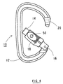
- the finger 14 is movable towards inside the body 12, allowing the opening of the carabiner ( Figure 4) to allow either the introduction of a rope or strap, or the attachment of the carabiner to a mooring member (not shown).
- the upper end of the body 12 is provided with a male retaining element 20 able to engage in a female attachment element 22 of the finger 14 when it returns to the closed position ( Figure 1) under the action of a return spring 24.
- the male element 20 has an inverted T structure comprising a tongue extended by a protuberance in the form of clevis.
- the female element 22 of the finger 14 is located opposite the axis 16 of pivot, and includes a recess of shape conjugated to the male element 20.
- the length of the locking ring 18 has a length lower than that of finger 14, and is permanently separated from axis 16 by an axial interval.
- the lower part of the ring 18 has a flange annular 30 engaged with play in a groove 32 of the finger 14.
- the upper part of the ring 18 is in look of the protrusion of the male element 20, which prevents any pivoting of the finger 14 inwards during a pushing action exerted perpendicular to the longitudinal direction of the ring 18.
- the upper edge of the locking ring 18 has a slot 38 authorizing the passage of the protrusion of the male element 20 when the ring 18 is in the second unlocked position.
- the opening of finger 14 is then possible by a pushing action rotating the finger 14 around the axis 16 towards the open position of FIG. 4.
- the movable finger 14 is further equipped with a lock 40 capable of blocking positively the ring 18 in the first locked position.
- the latch 40 includes a stud 42 telescopic mounted in a radial orifice 44 of the finger 14, and provided with a rounded abutment surface 46, in particular in the form of a ball.
- the nipple 42 is associated with a compression spring 48 housed in the orifice 44, and urging the abutment surface 46 in the radial direction.
- the locking ring 18 is provided with a circular hole 50 allowing the protruding from the abutment surface 46 of the stud 42 in the first locked position. In this positive locking position ( Figure 8), everything rotational movement of the ring 18 towards the second position unlocked is made impossible, and finger 14 remains closed with a total security, regardless of any effort exerted on the finger 14.
- the hole 50 for passage of the stud 42 is located at the bottom of a surface of grip 54 in the form of a bowl, which facilitates the driving action of the latch 40 for passage to the unlocked position.
- a blind notch 56 is provided in the cylindrical internal wall of the locking ring 18 at lock level 40, said notch being angularly offset from hole 50, and having a shape conjugate to that of the rounded abutment surface 46 of the stud 42.
- the abutment surface 46 of the stud 42 engages in the blind notch 56, so as to constitute a hard point. The release point of this hard point requires some effort at the start of the rotation of the ring 18, and independently of the direction of rotation.
- the angular offset between the hole 50 and the notch 56 of the ring lock 18 corresponds to the stroke necessary for the passage of the first locked position to the second unlocked position, and vice versa.
- the return spring 24 extends in a blind bore 60 and offset from the finger 14, the base of the spring 24 being associated with a tail 62 bearing on a rim 64 of the body 12. The bending of the spring 24 during the opening of the finger 14 tends to automatically return it to the closed position as soon as the user releases it.
- the latch 40 In the closed position of the carabiner 10 ( Figures 1, 2 and 5), the latch 40 is active for blocking the locking ring 18 in the first position locked.
- the upper part of the ring 18 constitutes a stop means which prevents any pivoting movement of the finger 14 towards the interior of the body 12.
- the spring 48 maintains the abutment surface 46 of the latch 40 in the hole 50 of the ring 18 to immobilize the latter in rotation ( Figure 8).
- the abutment surface 46 is protruding, and is visible from the outside.
- the opening of the movable finger 14 is possible following the rotational movement from the ring 18 to the second unlocked position, which movement is only authorized after the lock 40 has been released beforehand by a pushing action of the nipple 42 against the restoring force of the compression spring 48.
- the manual movement in rotation of the ring 18 can be operated in the clockwise, or counterclockwise, and the second unlocked position is obtained when the notch 56 of the ring 18 arrives opposite the stud 42 of the finger 14.
- the spring 48 then pushes the surface of stop 46 in the notch 56, so as to constitute a hard point 58 which maintains the ring 18 in said second position ( Figure 9).
- This connection internal hard point 58 between ring 18 and finger 14 is not visible from outside.
- the ring 18 is in the unlocked position of Figures 3 and 6, and it is then possible to rotate the finger 14 towards the position opening (figure 4).
- the return spring 24 returns automatically the finger 14 movable to the closed position ( Figure 3).
- the lock 40 nevertheless remains in the second unlocked position, indicated in Figure 9.
- the transition to the first locked position requires a manual actuation in rotation of the locking ring 18 causing at the start of the race, the release of hard point 58 following the reaction of the ring 18 on the abutment surface 46 causing the recess of the stud 42, and at the end the insertion of the abutment surface 46 into the hole 50 for the positive locking of the ring 18.
- the manual actuation movement of the locking ring 18 can be operated either in the direction of clockwise, or in the opposite direction.
- the locking ring 18 is made of metallic or plastic material and the lock 40 could be produced differently, in particular by means of a lever pivoting attachment.
Landscapes
- Engineering & Computer Science (AREA)
- General Engineering & Computer Science (AREA)
- Mechanical Engineering (AREA)
- Hooks, Suction Cups, And Attachment By Adhesive Means (AREA)
- Adornments (AREA)
- Supports Or Holders For Household Use (AREA)
- Soil Working Implements (AREA)
Applications Claiming Priority (2)
| Application Number | Priority Date | Filing Date | Title |
|---|---|---|---|
| FR9610800 | 1996-08-30 | ||
| FR9610800A FR2752896B1 (fr) | 1996-08-30 | 1996-08-30 | Mousqueton a verrou |
Publications (2)
| Publication Number | Publication Date |
|---|---|
| EP0826890A1 EP0826890A1 (fr) | 1998-03-04 |
| EP0826890B1 true EP0826890B1 (fr) | 2002-03-27 |
Family
ID=9495434
Family Applications (1)
| Application Number | Title | Priority Date | Filing Date |
|---|---|---|---|
| EP97410089A Expired - Lifetime EP0826890B1 (fr) | 1996-08-30 | 1997-08-12 | Mousqueton à verrou |
Country Status (8)
| Country | Link |
|---|---|
| US (1) | US5791025A (cs) |
| EP (1) | EP0826890B1 (cs) |
| JP (1) | JPH1089340A (cs) |
| AT (1) | ATE215187T1 (cs) |
| CZ (1) | CZ288811B6 (cs) |
| DE (1) | DE69711299T2 (cs) |
| ES (1) | ES2173409T3 (cs) |
| FR (1) | FR2752896B1 (cs) |
Families Citing this family (37)
| Publication number | Priority date | Publication date | Assignee | Title |
|---|---|---|---|---|
| GB0019136D0 (en) * | 2000-08-04 | 2000-09-27 | Dmm Eng Ltd | Karabiners |
| GB0024791D0 (en) * | 2000-10-10 | 2000-11-22 | Dmm Engineering Ltd | Device for adhering bricks,concrete blocks and the like |
| US20020174681A1 (en) * | 2001-04-13 | 2002-11-28 | Anna Godsey | Body jewelry clasp |
| FR2836964B1 (fr) | 2002-03-11 | 2004-06-25 | Zedel | Mousqueton equipe d'une bague de verrouillage a patte de separation |
| US6588076B1 (en) | 2002-04-08 | 2003-07-08 | Gary E. Choate | Carabiner with locking gate |
| EP1557617A4 (en) * | 2002-10-29 | 2009-12-16 | Daikin Ind Ltd | WATER EXHAUST STRUCTURE FOR AIR CONDITIONING SYSTEM |
| US6925690B2 (en) * | 2003-07-07 | 2005-08-09 | Jt International Distributors Inc. | Bullsnap |
| WO2005073571A1 (en) * | 2004-01-27 | 2005-08-11 | Thompson Rocke P | Carabiners having captive eye opening and methods of fabrication and use |
| US20050246874A1 (en) * | 2004-05-10 | 2005-11-10 | Hsu Samuel W | Carabiner with improved gate structure |
| CA2489047C (en) * | 2004-12-02 | 2015-08-04 | Corven Healthcare Inc. | Carabiner and connection tool for use with patient carrying systems |
| US7540074B2 (en) * | 2004-12-21 | 2009-06-02 | Techxotic, L.C. | Carabiner having reinforcing sleeve |
| FR2883344B1 (fr) * | 2005-03-17 | 2011-07-22 | Zedel | Mousqueton a bague de verrouillage |
| FR2883938B1 (fr) * | 2005-04-05 | 2009-10-09 | Zedel Soc Par Actions Simplifiee | Mousqueton a verrouillage automatique |
| US20070050956A1 (en) * | 2005-09-06 | 2007-03-08 | Bobby Hu | Apparatus for carrying tools |
| DE602007003900D1 (de) * | 2006-06-26 | 2010-02-04 | Tony Christianson | Schnappverschlusskarabinerhaken |
| US7946006B2 (en) * | 2006-07-10 | 2011-05-24 | Techxotic, L.C. | Carabiner having dual gates and associated methods |
| US20080104810A1 (en) * | 2006-11-07 | 2008-05-08 | Feng Chia Liang | Snap hook with slidable lock |
| US20100011547A1 (en) * | 2008-07-16 | 2010-01-21 | Castell Interlocks Inc. | Irreversible locking mechanism |
| US20100088945A1 (en) * | 2008-10-13 | 2010-04-15 | Gois John F | Hardened Purse Ring |
| GB0822250D0 (en) * | 2008-12-05 | 2009-01-14 | Dmm Engineering Ltd | Improvements in and relating to karabiners |
| FR2944842A1 (fr) | 2009-04-22 | 2010-10-29 | Zedel | Maillon d'attache a bague rotative verrouillable |
| US20100299893A1 (en) * | 2009-06-02 | 2010-12-02 | Feng-Chia Liang | Double locking snap hook device |
| US20100325848A1 (en) * | 2009-06-24 | 2010-12-30 | Feng Chia Liang | Snap hook with rotatable lock |
| US8474112B2 (en) * | 2009-07-29 | 2013-07-02 | Rock Exotica Llc | Carabiners with multi mode locking sleeves, methods of manufacturing such carabiners, and methods of using such carabiners |
| US8117721B2 (en) * | 2009-11-19 | 2012-02-21 | Gimmal Co., Ltd. | Snap hook having pivotal lock |
| US9003617B2 (en) * | 2009-12-11 | 2015-04-14 | Black Diamond Equipment Ltd. | Multi-chamber carabiner |
| US8276247B2 (en) | 2010-07-13 | 2012-10-02 | Gimmal Co., Ltd. | Snap hook with rotatable lock |
| US8695179B2 (en) * | 2010-08-20 | 2014-04-15 | Munchkin, Inc. | Hook article |
| KR101025183B1 (ko) * | 2010-09-27 | 2011-04-07 | (주) 선원 밸브 | 어구용 스냅링 |
| US8555470B2 (en) | 2011-05-24 | 2013-10-15 | Black Diamond Equipment, Ltd. | Magnetic carabiner system |
| FR2976638B1 (fr) * | 2011-06-16 | 2013-07-05 | Wichard | Mousqueton de securite |
| DE202013008111U1 (de) * | 2013-09-11 | 2013-10-24 | Skylotec Gmbh | Twist/Trilock Karabiner |
| JP6538370B2 (ja) * | 2015-02-26 | 2019-07-03 | 株式会社アガツマ | ジャングルジム用継手 |
| JP6538371B2 (ja) * | 2015-02-26 | 2019-07-03 | 株式会社アガツマ | ジャングルジム |
| US9958002B2 (en) * | 2016-07-18 | 2018-05-01 | Win Chance Metal Co., Ltd. | Dust-proof safety hook |
| CN112208769B (zh) * | 2020-09-25 | 2022-11-04 | 中国直升机设计研究所 | 一种直升机外吊挂货物挂钩收纳存放可调式锁闭机构 |
| US11898591B2 (en) | 2021-08-29 | 2024-02-13 | Make Ideas, LLC | Releasable coupling device |
Family Cites Families (7)
| Publication number | Priority date | Publication date | Assignee | Title |
|---|---|---|---|---|
| US831260A (en) * | 1904-09-06 | 1906-09-18 | Joseph Eugene Borlaug | Link or clevis. |
| FR2146703A5 (cs) * | 1971-07-21 | 1973-03-02 | Contat Freres | |
| FR2461146A1 (fr) * | 1979-07-12 | 1981-01-30 | Simond & Fils Ets Claudius | Mousqueton a verrouillage automatique |
| IT210132Z2 (it) * | 1985-05-24 | 1988-11-14 | Frechin Jean Paul | Sistema di aggancio tra il corpo ed il nottolino di un moschettone |
| US5287645A (en) * | 1989-08-15 | 1994-02-22 | Gemini Capital Group, Inc. | Purse ring |
| DE9110358U1 (de) * | 1991-08-22 | 1991-11-28 | Henssgen Karabinerhaken GmbH, 5603 Wülfrath | Karabinerhaken |
| FR2731255B1 (fr) * | 1995-03-02 | 1997-04-25 | Zedel | Mousqueton a bague de verrouillage |
-
1996
- 1996-08-30 FR FR9610800A patent/FR2752896B1/fr not_active Expired - Fee Related
-
1997
- 1997-08-12 ES ES97410089T patent/ES2173409T3/es not_active Expired - Lifetime
- 1997-08-12 AT AT97410089T patent/ATE215187T1/de not_active IP Right Cessation
- 1997-08-12 DE DE69711299T patent/DE69711299T2/de not_active Expired - Fee Related
- 1997-08-12 EP EP97410089A patent/EP0826890B1/fr not_active Expired - Lifetime
- 1997-08-21 US US08/915,577 patent/US5791025A/en not_active Expired - Fee Related
- 1997-08-25 CZ CZ19972689A patent/CZ288811B6/cs not_active IP Right Cessation
- 1997-08-28 JP JP9232822A patent/JPH1089340A/ja not_active Withdrawn
Also Published As
| Publication number | Publication date |
|---|---|
| JPH1089340A (ja) | 1998-04-07 |
| DE69711299D1 (de) | 2002-05-02 |
| US5791025A (en) | 1998-08-11 |
| DE69711299T2 (de) | 2002-10-02 |
| FR2752896B1 (fr) | 1998-11-27 |
| ATE215187T1 (de) | 2002-04-15 |
| CZ268997A3 (cs) | 1998-03-18 |
| EP0826890A1 (fr) | 1998-03-04 |
| CZ288811B6 (cs) | 2001-09-12 |
| ES2173409T3 (es) | 2002-10-16 |
| FR2752896A1 (fr) | 1998-03-06 |
Similar Documents
| Publication | Publication Date | Title |
|---|---|---|
| EP0826890A1 (fr) | Mousqueton à verrou | |
| EP1710456B1 (fr) | Mousqueton à verrouillage automatique | |
| EP0730102B1 (fr) | Mousqueton à bague de verrouillage | |
| FR2883344A1 (fr) | Mousqueton a bague de verrouillage | |
| EP2243972B1 (fr) | Maillon d'attache à bague rotative verrouillable | |
| EP1465507B1 (fr) | Boucle de fixation a auto-verrouillage et a reglage d une sa ngle | |
| EP2034198B1 (fr) | Mousqueton à doigt pivotant équipé d'une bague de verrouillage | |
| EP0847501B1 (fr) | Mousqueton de securite | |
| EP0779951B1 (fr) | Mousqueton man uvrable a distance, permettant d'amarrer un cordage | |
| EP2535602B1 (fr) | Mousqueton de sécurité | |
| EP0581693A1 (fr) | Mousqueton à galet de verrouillage automatique | |
| FR2976639A1 (fr) | Mousqueton de securite | |
| FR2699973A1 (fr) | Verrou à enclenchement de préférence automatique et son application notamment à un siège amovible de véhicule. | |
| FR2836964A1 (fr) | Mousqueton equipe d'une bague de verrouillage a patte de separation | |
| EP0536005B1 (fr) | Dispositif pour l'assemblage et le désassemblage rapide de deux pièces l'une sur l'autre | |
| EP0644340A2 (fr) | Dispositif d'accrochage à mousqueton, notamment pour l'amarrage de bateaux | |
| FR2485658A1 (fr) | Porte-mousqueton a verrouillage automatique | |
| CH472623A (fr) | Dispositif de raccordement de canalisations | |
| EP2615313A1 (fr) | Dispositif de connexion mécanique pour relier une charge à un support | |
| FR2461146A1 (fr) | Mousqueton a verrouillage automatique | |
| FR2517289A1 (fr) | Crochet de levage avec dispositif de securite | |
| EP1183434B1 (fr) | Dispositif de verrouillage d'un element de recouvrement sur un cadre support | |
| EP0070237B1 (fr) | Appareil de traction à ancrage par broche | |
| FR2725251A1 (fr) | Dispositif de securite notamment a l'egard des enfants pour bac de collecte de dechets | |
| FR2620193A1 (fr) | Verrouilleur pour raccord de tuyau |
Legal Events
| Date | Code | Title | Description |
|---|---|---|---|
| PUAI | Public reference made under article 153(3) epc to a published international application that has entered the european phase |
Free format text: ORIGINAL CODE: 0009012 |
|
| AK | Designated contracting states |
Kind code of ref document: A1 Designated state(s): AT DE ES GB IT |
|
| AX | Request for extension of the european patent |
Free format text: AL;LT;LV;RO;SI |
|
| 17P | Request for examination filed |
Effective date: 19980716 |
|
| AKX | Designation fees paid |
Free format text: AT DE ES GB IT |
|
| RBV | Designated contracting states (corrected) |
Designated state(s): AT DE ES GB IT |
|
| GRAG | Despatch of communication of intention to grant |
Free format text: ORIGINAL CODE: EPIDOS AGRA |
|
| GRAG | Despatch of communication of intention to grant |
Free format text: ORIGINAL CODE: EPIDOS AGRA |
|
| GRAH | Despatch of communication of intention to grant a patent |
Free format text: ORIGINAL CODE: EPIDOS IGRA |
|
| 17Q | First examination report despatched |
Effective date: 20010810 |
|
| GRAH | Despatch of communication of intention to grant a patent |
Free format text: ORIGINAL CODE: EPIDOS IGRA |
|
| REG | Reference to a national code |
Ref country code: GB Ref legal event code: IF02 |
|
| GRAA | (expected) grant |
Free format text: ORIGINAL CODE: 0009210 |
|
| AK | Designated contracting states |
Kind code of ref document: B1 Designated state(s): AT DE ES GB IT |
|
| REF | Corresponds to: |
Ref document number: 215187 Country of ref document: AT Date of ref document: 20020415 Kind code of ref document: T |
|
| REF | Corresponds to: |
Ref document number: 69711299 Country of ref document: DE Date of ref document: 20020502 |
|
| PGFP | Annual fee paid to national office [announced via postgrant information from national office to epo] |
Ref country code: GB Payment date: 20020807 Year of fee payment: 6 |
|
| PGFP | Annual fee paid to national office [announced via postgrant information from national office to epo] |
Ref country code: AT Payment date: 20020813 Year of fee payment: 6 |
|
| PGFP | Annual fee paid to national office [announced via postgrant information from national office to epo] |
Ref country code: DE Payment date: 20020821 Year of fee payment: 6 |
|
| REG | Reference to a national code |
Ref country code: ES Ref legal event code: FG2A Ref document number: 2173409 Country of ref document: ES Kind code of ref document: T3 |
|
| PLBE | No opposition filed within time limit |
Free format text: ORIGINAL CODE: 0009261 |
|
| STAA | Information on the status of an ep patent application or granted ep patent |
Free format text: STATUS: NO OPPOSITION FILED WITHIN TIME LIMIT |
|
| 26N | No opposition filed |
Effective date: 20021230 |
|
| PG25 | Lapsed in a contracting state [announced via postgrant information from national office to epo] |
Ref country code: GB Free format text: LAPSE BECAUSE OF NON-PAYMENT OF DUE FEES Effective date: 20030812 Ref country code: AT Free format text: LAPSE BECAUSE OF NON-PAYMENT OF DUE FEES Effective date: 20030812 |
|
| PGFP | Annual fee paid to national office [announced via postgrant information from national office to epo] |
Ref country code: ES Payment date: 20030926 Year of fee payment: 7 |
|
| PG25 | Lapsed in a contracting state [announced via postgrant information from national office to epo] |
Ref country code: DE Free format text: LAPSE BECAUSE OF NON-PAYMENT OF DUE FEES Effective date: 20040302 |
|
| GBPC | Gb: european patent ceased through non-payment of renewal fee |
Effective date: 20030812 |
|
| PG25 | Lapsed in a contracting state [announced via postgrant information from national office to epo] |
Ref country code: ES Free format text: LAPSE BECAUSE OF NON-PAYMENT OF DUE FEES Effective date: 20040813 |
|
| PG25 | Lapsed in a contracting state [announced via postgrant information from national office to epo] |
Ref country code: IT Free format text: LAPSE BECAUSE OF NON-PAYMENT OF DUE FEES Effective date: 20050812 |
|
| REG | Reference to a national code |
Ref country code: ES Ref legal event code: FD2A Effective date: 20040813 |