EP0826932A2 - Dispositif de sortie à buses - Google Patents
Dispositif de sortie à buses Download PDFInfo
- Publication number
- EP0826932A2 EP0826932A2 EP97114047A EP97114047A EP0826932A2 EP 0826932 A2 EP0826932 A2 EP 0826932A2 EP 97114047 A EP97114047 A EP 97114047A EP 97114047 A EP97114047 A EP 97114047A EP 0826932 A2 EP0826932 A2 EP 0826932A2
- Authority
- EP
- European Patent Office
- Prior art keywords
- nozzle
- nozzle outlet
- outlet according
- tube
- cover ring
- Prior art date
- Legal status (The legal status is an assumption and is not a legal conclusion. Google has not performed a legal analysis and makes no representation as to the accuracy of the status listed.)
- Granted
Links
- 238000005096 rolling process Methods 0.000 claims description 7
- 230000000295 complement effect Effects 0.000 claims description 4
- 238000004519 manufacturing process Methods 0.000 description 7
- 239000000463 material Substances 0.000 description 4
- 238000009434 installation Methods 0.000 description 3
- 238000010438 heat treatment Methods 0.000 description 1
- 238000002347 injection Methods 0.000 description 1
- 239000007924 injection Substances 0.000 description 1
- 230000000284 resting effect Effects 0.000 description 1
- 239000000243 solution Substances 0.000 description 1
- 238000003860 storage Methods 0.000 description 1
- 238000009423 ventilation Methods 0.000 description 1
- 238000003466 welding Methods 0.000 description 1
Images


Classifications
-
- F—MECHANICAL ENGINEERING; LIGHTING; HEATING; WEAPONS; BLASTING
- F24—HEATING; RANGES; VENTILATING
- F24F—AIR-CONDITIONING; AIR-HUMIDIFICATION; VENTILATION; USE OF AIR CURRENTS FOR SCREENING
- F24F13/00—Details common to, or for air-conditioning, air-humidification, ventilation or use of air currents for screening
- F24F13/02—Ducting arrangements
- F24F13/06—Outlets for directing or distributing air into rooms or spaces, e.g. ceiling air diffuser
Definitions
- the invention relates to a nozzle outlet for introducing Warm and / or cold air in a room via at least one Nozzle in a spherical cap, which is in an opening of a tube sits.
- Such nozzles are of various shapes and designs known and available on the market. With them there is air preferably introduced far into a room around this for example, heating up in very specific areas. It is important that the air flow can be localized desired locations of a room can be aligned.
- a nozzle outlet is known, in which Individual nozzles are inserted in a housing. Furthermore is off DE 1 763 599 a pivotable mouthpiece for ventilation devices known, which is in a hemispherical Carrier is movably mounted. This carrier is about fasteners with a wall or a Channel system connected. The disadvantage here is that the Long throw nozzle or the mouthpiece protrudes far into a room and a concealed installation is impossible or expensive.
- nozzle outlets By setting conventional nozzle outlets a mounting plate or a duct system separate facilities arise high assembly and also additional material costs. In addition, the manufacturing costs such nozzle outlets increased because they are more complex constructed, more complex to manufacture and assemble.
- the present invention is based on the object to create a nozzle outlet which the above disadvantage eliminated and with which a quick manufacture and Setting the nozzle outlet is possible. Furthermore, with the simplest means of rotating and swiveling the nozzle minimal manufacturing effort and quick assembly to be possible. Assembly, material and Manufacturing costs can be significantly reduced.
- This invention allows that in a tube or Pipe section a nozzle is used, which in the pipe is held by means of a cover ring so that it is in the Tube rotates and swivels.
- this cover ring uses this cover ring to attach the pipe a mounting plate.
- the cover ring is inserted into the tube.
- This is provided with cantilevered locking elements, which in Engage openings in the tube so that the cover ring is used releasably. It overlaps the nozzle and holds them with his trained on the guide ring Guide chamfer rotatable or pivotable in the tube.
- Locking elements in corresponding openings in the tube intervene inside or outside. You can do any many locking elements at any angle to each other be provided in a complementary manner arranged openings grip.
- the nozzle can be swiveled easily in the tube side the nozzle and in particular the calotte directed outwards assigned two opposite supports, which each have an upward curved sheet-like rolling surface exhibit.
- the support can also be on the calotte itself be trained.
- the rolling surface is after installation the nozzle on an edge inside the tube, which is marked by a Reduced diameter formed in the wall of the tube is.
- the nozzle can be moved back and forth via these supports be pivoted.
- the nozzle is over the Rolled surface of the support rolled on the inner edge, by additionally rotating the calotte by one middle axis adjustable every possible direction for the nozzle becomes.
- the nozzle is preferred, but not essential consists of two parts or manufactured in two parts can be. It consists of a long-throw nozzle, which in a half-shell-like dome is releasably used. Two preferably engage outside of an infeed frame the long-throw nozzle arranged locking pin in corresponding Resting openings of the calotte.
- the long throw nozzle has one tapering, nozzle-like or, if necessary, tapering Nozzle jacket on, which through a dome opening the calotte is guided or inserted there.
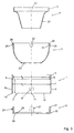
- FIG. 1 has a nozzle outlet R according to the invention outer cylindrical tube 1, which is open on both sides is.
- a cover ring 5 overlaps the cap 3 and closes on the outlet side, the opening between cap 3 and tube 1 further features and details of Figures 1 and 2 referred to later.
- FIG. 3 shows a cross section of the tube 1, which has a larger inner diameter d 1 in the lower section in the region of a length l than a section with an inner diameter d 2 adjoining it.
- This pipe 1 can be designed as a pipe section and, if necessary, can be connected directly to a duct of an air guidance system.
- a circumferential edge 6 is created inside the tube 1 and is used as a stop for the calotte 3.
- a wall 7 is thinner than a cylinder section 8 adjoining it in the area of the inner diameter d 2 .
- openings 9 are provided, which are square here. These openings 9 can but also have a different shape. Each spaced apart there are four openings 9 in the wall 7 at an angle of approximately 90 ° of the tube 1 provided.
- the lower edge 10 of the Pipe 1 pinnacles 11 placed. These are preferred the same width as the width of the openings 9.
- the tube 1 can with the assembly of the nozzle outlet R.
- a mounting plate 12, as shown in Fig. 4 is to be connected.
- the mounting plate 12 has one Passage opening 13 with additional recesses 14, which are preferably arranged at an angle of 90 ° to each other are. These recesses 14 correspond approximately to that cross-sectional shape of the crenellations 11 of the tube 1.
- the Battlements 11 engage in the assembly of the tube 1 in the Recesses 14 of the mounting plate 12.
- the lower edge 10 of the Tube 1 on the edge regions 15 of the mounting plate 12 near the passage opening 13.
- the tube 1 is with the Fixing plate 12 fixed and against twisting or Secured slipping.
- the long throw nozzle 4 has a Inlet frame 19 on which a nozzle-like tapered Nozzle jacket 20 connects.
- the shape of this long throw nozzle 4 is of a conventional type, as for example in DE-OS 31 24 876 is described.
- a special feature of this long throw nozzle 4 is that to the outside protruding from the inlet frame 19, as in FIG. 3 indicated by dashed lines, at least two opposite one another Locking pin 21 are provided. This locking pin 21 engage when inserting long throw nozzle 4 and Dome 3 in corresponding complementary manner on dome 3 arranged latching openings 22.
- the inlet frame is located 19 close to an inner wall 23 of the calotte 3, the Nozzle jacket 20 of the long-range nozzle 4, as in FIG. 1 shown, reaches through a dome opening 24 and there is kept centered. Dome 3 and long throw nozzle 4 can also be formed in one piece.
- the calotte 3 By connecting the locking pins 21 to the long throw nozzle 4 with correspondingly suitable latching openings 22 in the edge area the calotte 3 will also be quick to install Disassembly of the individual components possible. Not applicable here any welding, riveting, screwing or similar connections, which reduces manufacturing and assembly costs.
- supports 25 according to the invention which are arranged on the outside of the calotte 3. These can glued or directly molded on the calotte 3 itself be. They are in the upper edge area of the calotte 3 preferably opposite at an angle of approximately 180 ° arranged to each other.
- the support has 25 directed upwards an arched, semicircular extending rolling surface 26.
- This rolling surface 26 lies when the long throw nozzle 4 and the spherical cap 3 into the tube 1 are inserted on the circumferential edge 6 of the tube 1 on.
- a radius r of the arc of the rolling surface 26 determines a point P around which the calotte 3 in the tube 1 is pivotally mounted.
- the storage of the calotte 3 in the tube 1 causes the long throw nozzle 4 as by the double arrow z shown, is pivotable back and forth.
- the cover ring 5 overlaps the calotte 3 when inserting or fitting the cover ring 5 corresponding locking elements 27 in the openings 9 of the tube 1 a.
- the guide ring 28 of the Cover ring 5, which faces inward Opening has an obliquely inclined guide chamfer 29, formed an outer panel. Along the lead chamfer 29 the dome 3 is held when pivoting and rotating and led.
- the cover ring are also directed outwards Support surface 30 is provided.
- Each bearing surface 30 lies when installing or when clipping the cover ring 5 in the Tube 1 on the crenellations 11 of tube 1. Between each adjacent battlements 11 arise along the lower edge 10 the tube 1 and the bearing surface 30 gap sections 18, as indicated in Figures 1 and 2. In these gap sections 18 grip edge areas 15 of the mounting plate 12 when the cover ring 5 in the tube 1 with intermediate Fastening plate 12 is inserted.
- the mounting plate 12 can be omitted if necessary, if the pipe 1 directly, for example, in a ceiling or Wall is inserted.
- a multiplicity of nozzle outlets R can be used in a fastening plate 12.
- the arrangement of the individual nozzle outlets to one another can be chosen as desired.
Landscapes
- Engineering & Computer Science (AREA)
- Chemical & Material Sciences (AREA)
- Combustion & Propulsion (AREA)
- Mechanical Engineering (AREA)
- General Engineering & Computer Science (AREA)
- Containers And Packaging Bodies Having A Special Means To Remove Contents (AREA)
- Closures For Containers (AREA)
- Apparatus For Making Beverages (AREA)
- Percussion Or Vibration Massage (AREA)
- Sampling And Sample Adjustment (AREA)
- Nozzles (AREA)
- Duct Arrangements (AREA)
Applications Claiming Priority (2)
| Application Number | Priority Date | Filing Date | Title |
|---|---|---|---|
| DE19634936 | 1996-08-29 | ||
| DE19634936A DE19634936C2 (de) | 1996-08-29 | 1996-08-29 | Düsenauslaß |
Publications (3)
| Publication Number | Publication Date |
|---|---|
| EP0826932A2 true EP0826932A2 (fr) | 1998-03-04 |
| EP0826932A3 EP0826932A3 (fr) | 2000-03-29 |
| EP0826932B1 EP0826932B1 (fr) | 2003-05-28 |
Family
ID=7804025
Family Applications (1)
| Application Number | Title | Priority Date | Filing Date |
|---|---|---|---|
| EP97114047A Expired - Lifetime EP0826932B1 (fr) | 1996-08-29 | 1997-08-14 | Dispositif de sortie à buses |
Country Status (4)
| Country | Link |
|---|---|
| EP (1) | EP0826932B1 (fr) |
| AT (1) | ATE241785T1 (fr) |
| DE (2) | DE19634936C2 (fr) |
| ES (1) | ES2200099T3 (fr) |
Cited By (2)
| Publication number | Priority date | Publication date | Assignee | Title |
|---|---|---|---|---|
| ES2192470A1 (es) * | 2002-01-16 | 2003-10-01 | Ind Diru S L | Dispositivo de salida de aire orientable. |
| WO2016127195A1 (fr) | 2015-02-13 | 2016-08-18 | Merlin Technology Gmbh | Buse à jet longue portée pour l'introduction d'air |
Families Citing this family (2)
| Publication number | Priority date | Publication date | Assignee | Title |
|---|---|---|---|---|
| DE19740332C1 (de) * | 1997-09-13 | 1998-11-12 | Schako Metallwarenfabrik | Luftauslass |
| DE202012101832U1 (de) | 2012-05-18 | 2012-06-15 | Siegle + Epple Gmbh & Co. Kg Luft- Und Klimatechnik | Luftdurchlassvorrichtung zur Belüftung |
Citations (2)
| Publication number | Priority date | Publication date | Assignee | Title |
|---|---|---|---|---|
| DE1763599A1 (de) | 1965-08-16 | 1972-01-05 | Licentia Gmbh | Axial fortschreitende Roehrenwicklung fuer Transformatoren,Drosselspulen u.dgl.fuer hohe Nennspannungen |
| DE3838419A1 (de) | 1988-11-12 | 1990-05-17 | Schako Metallwarenfabrik | Duesenauslass |
Family Cites Families (7)
| Publication number | Priority date | Publication date | Assignee | Title |
|---|---|---|---|---|
| DE1763566U (de) * | 1958-01-08 | 1958-03-20 | Schilde Maschb Ag | Mundstueck fuer belueftungseinrichtungen u. dgl. |
| DE1917945A1 (de) * | 1969-03-10 | 1970-10-15 | Stephan Erich | Schalungsnagel |
| GB1319449A (en) * | 1969-08-18 | 1973-06-06 | Creators Ltd | Nozzles for ventilating and heating systems |
| DE3124876C2 (de) * | 1981-06-25 | 1985-09-19 | Schako Metallwarenfabrik Ferdinand Schad Kg, 7201 Kolbingen | Weitwurfdüse |
| DE8613078U1 (de) * | 1986-05-14 | 1987-06-11 | Schako Metallwarenfabrik Ferdinand Schad KG Zweigniederlassung Kolbingen, 7201 Kolbingen | Düseneinrichtung für eine Klimaanlage |
| IT231376Y1 (it) * | 1993-04-30 | 1999-08-03 | Foggini Progetti | Bocchetta di erogazione dell'aria di climatizzazione per autoveicoli con griglia di diffusione orientabile. |
| DE9420413U1 (de) * | 1994-12-21 | 1995-02-16 | Gebrüder Trox, GmbH, 47506 Neukirchen-Vluyn | Düseneinrichtung zur Belüftung von Räumen mit einem Einbaurahmen und einer schwenkbaren Düse, die eine äußere Führungswand und eine innere Düsenwand aufweist |
-
1996
- 1996-08-29 DE DE19634936A patent/DE19634936C2/de not_active Expired - Fee Related
-
1997
- 1997-08-14 ES ES97114047T patent/ES2200099T3/es not_active Expired - Lifetime
- 1997-08-14 DE DE59710159T patent/DE59710159D1/de not_active Expired - Lifetime
- 1997-08-14 EP EP97114047A patent/EP0826932B1/fr not_active Expired - Lifetime
- 1997-08-14 AT AT97114047T patent/ATE241785T1/de active
Patent Citations (2)
| Publication number | Priority date | Publication date | Assignee | Title |
|---|---|---|---|---|
| DE1763599A1 (de) | 1965-08-16 | 1972-01-05 | Licentia Gmbh | Axial fortschreitende Roehrenwicklung fuer Transformatoren,Drosselspulen u.dgl.fuer hohe Nennspannungen |
| DE3838419A1 (de) | 1988-11-12 | 1990-05-17 | Schako Metallwarenfabrik | Duesenauslass |
Cited By (2)
| Publication number | Priority date | Publication date | Assignee | Title |
|---|---|---|---|---|
| ES2192470A1 (es) * | 2002-01-16 | 2003-10-01 | Ind Diru S L | Dispositivo de salida de aire orientable. |
| WO2016127195A1 (fr) | 2015-02-13 | 2016-08-18 | Merlin Technology Gmbh | Buse à jet longue portée pour l'introduction d'air |
Also Published As
| Publication number | Publication date |
|---|---|
| DE59710159D1 (de) | 2003-07-03 |
| DE19634936A1 (de) | 1998-03-05 |
| ES2200099T3 (es) | 2004-03-01 |
| EP0826932A3 (fr) | 2000-03-29 |
| ATE241785T1 (de) | 2003-06-15 |
| DE19634936C2 (de) | 2000-12-07 |
| EP0826932B1 (fr) | 2003-05-28 |
Similar Documents
| Publication | Publication Date | Title |
|---|---|---|
| DE19648736C1 (de) | Belüftungsdüse | |
| DE2114297A1 (de) | Belueftungsvorrichtung | |
| DE102017115012B3 (de) | Belüftungskanal für eine Lüftungsvorrichtung eines Kraftfahrzeugs | |
| DE102007018022C5 (de) | Luftdüse | |
| DE3740714A1 (de) | Luftstromverteiler | |
| EP1331116A2 (fr) | Buse à air | |
| DE3810482C2 (fr) | ||
| DE102004013171B3 (de) | Luftdüse | |
| DE2716993A1 (de) | Vorrichtung zur belueftung und/oder klimatisierung von raeumen | |
| DE10046721B4 (de) | Lüftungsdüse | |
| EP2117860B1 (fr) | Aérateur, notamment pour un véhicule automobile | |
| EP0826932B1 (fr) | Dispositif de sortie à buses | |
| WO2019233877A1 (fr) | Diffuseur d'air destiné à introduire de l'air dans l'habitacle d'un véhicule à moteur | |
| EP0269923B1 (fr) | Sortie d'air | |
| DE10232422A1 (de) | Luftklappenanordnung | |
| EP0816772B1 (fr) | Sortie d'air | |
| DE3429710C2 (fr) | ||
| DE10212293B4 (de) | Luftauslass, insbesondere Luftauslass für den Wandeinbau | |
| DE19719879B4 (de) | Luftverteilungsvorrichtung | |
| DE19750509B4 (de) | Luftverteilervorrichtung | |
| EP0503550A2 (fr) | Sortie d'air, notamment bouche mélangeur à écoulement en spirales | |
| EP2093333A2 (fr) | Robinetterie de distribution d'eau sanitaire comprenant un dispositif de direction du jet permettant de dévier l'écoulement de l'eau sortant | |
| DE102019102456A1 (de) | Luftauslasseinrichtung insbesondere für Klimatisierungsanlagen von Kraftfahrzeugen | |
| EP1740402B1 (fr) | Dispositif d'aeration pour vehicule | |
| DE10149909B4 (de) | Luftauslass |
Legal Events
| Date | Code | Title | Description |
|---|---|---|---|
| PUAI | Public reference made under article 153(3) epc to a published international application that has entered the european phase |
Free format text: ORIGINAL CODE: 0009012 |
|
| AK | Designated contracting states |
Kind code of ref document: A2 Designated state(s): AT BE CH DE ES FR GB GR IT LI LU NL PT |
|
| AX | Request for extension of the european patent |
Free format text: AL;LT;LV;RO;SI |
|
| PUAL | Search report despatched |
Free format text: ORIGINAL CODE: 0009013 |
|
| AK | Designated contracting states |
Kind code of ref document: A3 Designated state(s): AT BE CH DE DK ES FI FR GB GR IE IT LI LU MC NL PT SE |
|
| AX | Request for extension of the european patent |
Free format text: AL;LT;LV;RO;SI |
|
| 17P | Request for examination filed |
Effective date: 20000509 |
|
| AKX | Designation fees paid |
Free format text: AT BE CH DE ES FR GB GR IT LI LU NL PT |
|
| 17Q | First examination report despatched |
Effective date: 20020405 |
|
| GRAH | Despatch of communication of intention to grant a patent |
Free format text: ORIGINAL CODE: EPIDOS IGRA |
|
| GRAH | Despatch of communication of intention to grant a patent |
Free format text: ORIGINAL CODE: EPIDOS IGRA |
|
| GRAA | (expected) grant |
Free format text: ORIGINAL CODE: 0009210 |
|
| AK | Designated contracting states |
Designated state(s): AT BE CH DE ES FR GB GR IT LI LU NL PT |
|
| REG | Reference to a national code |
Ref country code: GB Ref legal event code: FG4D Free format text: NOT ENGLISH |
|
| REG | Reference to a national code |
Ref country code: CH Ref legal event code: EP |
|
| REF | Corresponds to: |
Ref document number: 59710159 Country of ref document: DE Date of ref document: 20030703 Kind code of ref document: P |
|
| GBT | Gb: translation of ep patent filed (gb section 77(6)(a)/1977) |
Effective date: 20030728 |
|
| PG25 | Lapsed in a contracting state [announced via postgrant information from national office to epo] |
Ref country code: PT Free format text: LAPSE BECAUSE OF FAILURE TO SUBMIT A TRANSLATION OF THE DESCRIPTION OR TO PAY THE FEE WITHIN THE PRESCRIBED TIME-LIMIT Effective date: 20030828 |
|
| RAP2 | Party data changed (patent owner data changed or rights of a patent transferred) |
Owner name: SCHAKO KLIMA LUFT FERDINAND SCHAD KG |
|
| REG | Reference to a national code |
Ref country code: CH Ref legal event code: NV Representative=s name: FIAMMENGHI-FIAMMENGHI |
|
| REG | Reference to a national code |
Ref country code: GR Ref legal event code: EP Ref document number: 20030403315 Country of ref document: GR |
|
| NLT2 | Nl: modifications (of names), taken from the european patent patent bulletin |
Owner name: SCHAKO KLIMA LUFT FERDINAND SCHAD KG |
|
| NLT1 | Nl: modifications of names registered in virtue of documents presented to the patent office pursuant to art. 16 a, paragraph 1 |
Owner name: SCHAKO KLIMA LUFT FERDINAND SCHAD KG |
|
| REG | Reference to a national code |
Ref country code: ES Ref legal event code: FG2A Ref document number: 2200099 Country of ref document: ES Kind code of ref document: T3 |
|
| PLBE | No opposition filed within time limit |
Free format text: ORIGINAL CODE: 0009261 |
|
| STAA | Information on the status of an ep patent application or granted ep patent |
Free format text: STATUS: NO OPPOSITION FILED WITHIN TIME LIMIT |
|
| 26N | No opposition filed |
Effective date: 20040302 |
|
| REG | Reference to a national code |
Ref country code: DE Ref legal event code: R082 Ref document number: 59710159 Country of ref document: DE Representative=s name: PATENTANWAELTE UND RECHTSANWALT WEISS, ARAT & , DE Ref country code: DE Ref legal event code: R082 Ref document number: 59710159 Country of ref document: DE Representative=s name: PATENTANWAELTE UND RECHTSANWALT DR. WEISS, ARA, DE |
|
| REG | Reference to a national code |
Ref country code: FR Ref legal event code: PLFP Year of fee payment: 20 |
|
| PGFP | Annual fee paid to national office [announced via postgrant information from national office to epo] |
Ref country code: LU Payment date: 20160823 Year of fee payment: 20 Ref country code: NL Payment date: 20160819 Year of fee payment: 20 |
|
| PGFP | Annual fee paid to national office [announced via postgrant information from national office to epo] |
Ref country code: CH Payment date: 20160819 Year of fee payment: 20 Ref country code: GB Payment date: 20160819 Year of fee payment: 20 Ref country code: IT Payment date: 20160825 Year of fee payment: 20 |
|
| PGFP | Annual fee paid to national office [announced via postgrant information from national office to epo] |
Ref country code: AT Payment date: 20160822 Year of fee payment: 20 Ref country code: FR Payment date: 20160822 Year of fee payment: 20 Ref country code: GR Payment date: 20160822 Year of fee payment: 20 |
|
| PGFP | Annual fee paid to national office [announced via postgrant information from national office to epo] |
Ref country code: ES Payment date: 20160823 Year of fee payment: 20 Ref country code: BE Payment date: 20160819 Year of fee payment: 20 |
|
| PGFP | Annual fee paid to national office [announced via postgrant information from national office to epo] |
Ref country code: DE Payment date: 20161028 Year of fee payment: 20 |
|
| REG | Reference to a national code |
Ref country code: DE Ref legal event code: R071 Ref document number: 59710159 Country of ref document: DE |
|
| REG | Reference to a national code |
Ref country code: NL Ref legal event code: MK Effective date: 20170813 |
|
| REG | Reference to a national code |
Ref country code: CH Ref legal event code: PL |
|
| REG | Reference to a national code |
Ref country code: GB Ref legal event code: PE20 Expiry date: 20170813 |
|
| REG | Reference to a national code |
Ref country code: AT Ref legal event code: MK07 Ref document number: 241785 Country of ref document: AT Kind code of ref document: T Effective date: 20170814 |
|
| REG | Reference to a national code |
Ref country code: BE Ref legal event code: MK Effective date: 20170814 |
|
| PG25 | Lapsed in a contracting state [announced via postgrant information from national office to epo] |
Ref country code: GB Free format text: LAPSE BECAUSE OF EXPIRATION OF PROTECTION Effective date: 20170813 |
|
| REG | Reference to a national code |
Ref country code: ES Ref legal event code: FD2A Effective date: 20180508 |
|
| PG25 | Lapsed in a contracting state [announced via postgrant information from national office to epo] |
Ref country code: ES Free format text: LAPSE BECAUSE OF EXPIRATION OF PROTECTION Effective date: 20170815 |