EP0826954A2 - Procédé et dispositif d'essai d'étanchéité d'un élément creux - Google Patents
Procédé et dispositif d'essai d'étanchéité d'un élément creux Download PDFInfo
- Publication number
- EP0826954A2 EP0826954A2 EP97306088A EP97306088A EP0826954A2 EP 0826954 A2 EP0826954 A2 EP 0826954A2 EP 97306088 A EP97306088 A EP 97306088A EP 97306088 A EP97306088 A EP 97306088A EP 0826954 A2 EP0826954 A2 EP 0826954A2
- Authority
- EP
- European Patent Office
- Prior art keywords
- gas
- leakage
- testing
- hollow member
- hollow body
- Prior art date
- Legal status (The legal status is an assumption and is not a legal conclusion. Google has not performed a legal analysis and makes no representation as to the accuracy of the status listed.)
- Granted
Links
Images




Classifications
-
- G—PHYSICS
- G01—MEASURING; TESTING
- G01M—TESTING STATIC OR DYNAMIC BALANCE OF MACHINES OR STRUCTURES; TESTING OF STRUCTURES OR APPARATUS, NOT OTHERWISE PROVIDED FOR
- G01M3/00—Investigating fluid-tightness of structures
- G01M3/02—Investigating fluid-tightness of structures by using fluid or vacuum
- G01M3/04—Investigating fluid-tightness of structures by using fluid or vacuum by detecting the presence of fluid at the leakage point
- G01M3/20—Investigating fluid-tightness of structures by using fluid or vacuum by detecting the presence of fluid at the leakage point using special tracer materials, e.g. dye, fluorescent material, radioactive material
- G01M3/22—Investigating fluid-tightness of structures by using fluid or vacuum by detecting the presence of fluid at the leakage point using special tracer materials, e.g. dye, fluorescent material, radioactive material for pipes, cables or tubes; for pipe joints or seals; for valves; for welds; for containers, e.g. radiators
- G01M3/226—Investigating fluid-tightness of structures by using fluid or vacuum by detecting the presence of fluid at the leakage point using special tracer materials, e.g. dye, fluorescent material, radioactive material for pipes, cables or tubes; for pipe joints or seals; for valves; for welds; for containers, e.g. radiators for containers, e.g. radiators
- G01M3/227—Investigating fluid-tightness of structures by using fluid or vacuum by detecting the presence of fluid at the leakage point using special tracer materials, e.g. dye, fluorescent material, radioactive material for pipes, cables or tubes; for pipe joints or seals; for valves; for welds; for containers, e.g. radiators for containers, e.g. radiators for flexible or elastic containers
Definitions
- the present invention relates to an apparatus for and a method of testing whether or not a hollow member of a hollow shape such as a laminated tube, a can or a can lid has a leakage.
- a member such as the laminated tube or the can may be formed by jointing its parts.
- the member may also be formed by jointing a plurality of members such as a body and a head piece, or a can body and a can lid.
- these members are required to have a sealing property. It is, therefore, necessary to test whether or not a leakage portion is due to an insufficient joint or due to a defect in the materials, before the containers are filled with their contents.
- An apparatus for this test is disclosed in JU-A-6-56744 (or JU-B-6-48373).
- the apparatus tests the leakage of a gas in a container such as a can.
- This apparatus is constructed to test the leakage of a container of a sealed structure, by pressuring and injecting a testing gas into the inside of the container, by arranging a gas detecting sensor around the container, and by rotating the container and the gas detecting sensor relative to each other to detect the testing gas leaking to the outer circumference of the container.
- the above-mentioned apparatus detects the leakage by detecting the gas, as pressurized and injected into the inside of the container, by the gas detecting sensor. Therefore, the gas to be employed cannot but be a gas which is not present in the ambient atmosphere. In short, the apparatus of the prior art has to employ a special gas. Prior to the test, moreover, the gas has to be completely excluded from the atmosphere. For an accurate test without being influenced by the residual gas, therefore, the control process for automation may probably be complicated.
- the apparatus of the prior art is constructed such that the testing gas, as pressurized and injected into the container, is blown out from the container and guided into the gas detecting sensor thereby to decide the leakage from the container.
- the leakage is restricted or when the testing gas diffuses along the wall face of the container, therefore, it is difficult to capture the testing gas and to guide it into the gas detecting sensor.
- the prior apparatus has been difficult to let the prior apparatus have a necessary and sufficient detecting accuracy of leakage.
- the conventional apparatus detects the leakage by rotating the container, moreover, the spacing between the sensor and the container body is not constant, when the container itself does not have a cylindrical shape, so that the container partially leaves the sensor to make it impossible to detect the leakage at the spaced portion.
- the leaking portion or the defect of the container may be a fine pore or a hole, as formed along the face due to the insufficient joint, and the gas flow emanating from such leaking portion will not always be injected outward normal to the container face.
- the conventional apparatus is not equipped with means for guiding the gas positively to the sensor and may fail to detect the gas which leaks from the fine pore or the facial hole so that it is deficient in the accuracy of detecting the leakage.
- the conventional apparatus is constructed to rotate the container and the sensor relatively, even with a guard member for guiding the gas near the outer circumference of the container into the detector, a small quantity of gas which leaked from the pore or the hole may flow along the circumferential wall face of the container and may not be accurately detected.
- These disadvantages become the more serious for the higher relative rotating speeds of the container and the sensor. After all, it is difficult to speed up the leakage test of the container.
- An object of the present invention is to provide an apparatus and a method capable of testing highly accurately whether or not a hollow member such as a container or its parts has a leakage.
- a leakage testing apparatus for testing whether or not a hollow member of a hollow shape has a leakage, comprising; a hold mechanism for holding the hollow member such that the inside and the outside are gas-tight isolated from each other; an injection mechanism for injecting a testing gas into the hollow member held by the hold mechanism; and leakage detecting means for sucking the gas around the hollow member held by the hold mechanism, to detect the leakage on the basis of the concentration of the testing gas in the sucked gas.
- the hollow member to be tested is held at first in the state in which its inside and outside are isolated gas-tight, and then the gas in the outer circumference of the hollow member is sucked by the leakage detecting means.
- the testing gas is injected into the inside of the hollow member, the gas in the outer circumference of the hollow member is sucked by the leakage detecting means.
- the testing gas is not injected into the inside of the hollow member and when the hollow member has no leaking portion, the atmosphere is exclusively sucked by the leakage detecting means. If the hollow member has a leaking portion, on the other hand, the testing gas is mixed into the ambient gas around the hollow member and is sucked by the leakage detecting means.
- the apparatus of the present invention is simple in operations because it sucks the ambient gas around the entirety of the outer circumference of the hollow member and detects the concentration of the testing gas in the sucked gas. Moreover, the apparatus can detect the presence of the leaking portion in the hollow member promptly and accurately because it can capture the testing gas which leaked from the hollow member, without fail.
- a method of detecting whether or not a hollow member has a gas leakage comprising: setting the measured value of the concentration of a testing gas, as contained in an ambient gas of the hollow member, as a reference value; injecting the testing gas into the inside of the hollow member; sucking and collecting the ambient gas around the hollow member; measuring the concentration of the testing gas in the sucked and collected ambient gas; and deciding whether or not the leakage from the hollow member is, by comparing the measured value and the reference value.
- the concentration of the testing gas in the ambient gas when the testing gas is not fed and the concentration of the testing gas in the ambient gas when the testing gas is fed to the inside of the hollow member are compared so that the leakage from the hollow mamber can be decided when the testing gas concentration is relatively high. This makes it possible to perform the so-called "open type leakage test" with reference to the ambient gas.
- a hollow body to be tested in the present invention is exemplified by a hollow body (or member) 1 for the laminated tube which can be used for low-acidic fluid food and retorted for a long-term storage.
- this hollow body 1 is a flexible container which is composed by a head piece 2 and a cylindrical body member 3 fixed gas-tight each other by suitable means such as by welding or jointing them.
- the head piece 2 of the hollow member 1 is covered on its inner face with a metal foil (e.g., resin-coated aluminum foil) and is sealed at its leading end opening with the metal foil 4.
- a metal foil e.g., resin-coated aluminum foil
- the body member 3 of the hollow body 1 is generally formed of the material which has a metal (e.g., aluminum foil) sandwiched between the inner and outer layers of polypropylene (PP).
- a metal e.g., aluminum foil
- PP polypropylene
- FIG. 1 is a schematic diagram showing the entirety of the leakage testing apparatus 5
- Fig. 2 is an enlarged section of a portion of the leakage testing apparatus 5 and shows the state in which the hollow body 1 to be tested is fitted in a head cover 17 of the leakage testing apparatus 5.
- the apparatus 5 is equipped with an injection nozzle head 6 which is inserted into and supports the hollow body 1 from the inside.
- This injection nozzle head 6 forms a part of a retaining mechanism of the present invention and is exemplified by a generally cylindrical member having a smaller external diameter than the internal diameter of the body portion of the hollow body 1.
- the injection nozzle head 6 is equipped with a chuck 8 for defining a sealed space 7, when brought into contact with the inner circumference of the body member 3, in the hollow body 1 at the side of the head piece 2.
- a top piece 9 for injecting the testing gas into the sealed space 7.
- a neck portion 10 which is projected on the center axis to fit the annular chuck 8 on its outer circumference.
- This chuck 8 is made of an elastic material such as rubber so that it is radially expanded when fed therein with pressurized air.
- the chuck 8 is opened at 8A in its inner circumference fitting the neck portion 10.
- an air passage 6A is formed through the body portion of the injection nozzle head 6.
- a chuck fastening air feeder 11 is connected to this air passage 6A.
- This chuck fastening air feeder 11 is composed mainly of a pressurized air source such as a compressor and a valve for controlling the feed/discharge of the pressurized air and is electrically controlled to feed the pressurized air to the injection nozzle head 6 thereby to expand the chuck 8 radially.
- the top piece 9 has a disc-shaped portion having a diameter substantially equal to the external diameter of the injection nozzle head 6, and testing gas feed passages 13 are radially formed in the disc-shaped portion.
- the feed passages 13 are so formed as to blow the testing gas radially of the hollow body 1 so that the metal foil 4, as adhered to the inner face of the head piece 2, may be exposed neither directly to the dynamic pressure of the testing gas nor broken by the gas.
- a cylindrical portion 91, as located at the central portion of the leading end of the injection nozzle head 6, is a projection for minimizing the capacity of the sealed space 7. As the capacity of the sealed space 7 is the smaller, the time period, as required for the sealed space 7 to be filled up with the testing gas, can be made the shorter thereby to raise the testing speed.
- the testing gas feed passage 13 is directed, when the injection nozzle head 6 is inserted into the hollow body 1, toward a weld (or a joint) body 14 between the head piece 2 and the shoulder of the body member 3 so that it can blow the testing gas to the weld (or the joint) 14.
- the shown embodiment is constructed mainly to test the leakage at the weld 14.
- the portion to be tested of its leakage should not be limited to the shoulder. In short, it is sufficient that the blow position of the testing gas is located in the hollow body.
- a pipe 15 for feeding the testing gas is connected through the central portion of the neck portion 10 to the top piece 9.
- This pipe 15 is made to communicate through a solenoid valve 16 with the testing gas source such as a gas cylinders (not- shown) so that the feed of the testing gas to the inside of the sealed space 7 of the hollow body 1 is controlled by the solenoid valve 16.
- the testing gas source such as a gas cylinders (not- shown)
- a pipe communicating with a vacuum source (not-shown) is connected to the solenoid valve 16 to discharge the residual gas from the inside of the sealed space 7 through the pipe 15.
- the leakage testing gas is frequently used helium gas, which is so special as to have raise the cost.
- helium gas As an inexpensive gas, there is enumerated the nitrogen gas which is much contained in the atmosphere. This makes it difficult to decide whether or not the nitrogen gas, even if detected, comes from the leakage, and the detection accuracy may fall.
- the testing gas is preferably exemplified by carbon dioxide gas. The reason why the carbon dioxide is adopted is not only because it is inexpensive but also because its content in the atmosphere is low.
- the carbon dioxide concentration in the sampled gas is abnormally raised (or highly changed) even if its leakage is small, so that the decision of the presence/absence of leakage, i.e., the detection of leakage can be facilitated to enhance the detection accuracy.
- This test could be made by using the nitrogen gas, the helium gas and other gases.
- the head cover 17 for receiving the leading end portion of the hollow body 1 including the head piece 2 is arranged at the leading end side of the injection nozzle head 6.
- This head cover 17 is a member having a hollow portion (or recess) 18 which is shaped to have a contour generally identical to that of the leading end portion of the hollow body 1.
- inlet holes 19 for introducing the atmosphere into the hollow portion 18.
- the portions confronting the outer circumference of the body member 3 with the leading end portion of the hollow body 1 being inserted into the hollow portion there are radially formed equidistantly all over the circumference the plurality of inlet holes 19 which are extended radially inward through the head cover 17.
- the inlet holes 19 are so determined in number and diameter that they can suck the atmosphere in an amount corresponding to the suction of a pump 28 (29) and uniformly from the whole circumference. As a result, the hollow portion 18 in the head cover 17 is kept open to the atmosphere at all times.
- ribs 20 which are positioned to confront the shoulder portion of the head piece 2. These ribs 20 regulate the leading end portion of the hollow body 1 by abutting against the shoulder portion of the head piece 2 other than the weld 14. Moreover, the ribs 20 are spaced from one another so that they may not check the flow of gas.
- suction hole 22 In the deepest portion of the hollow portion 18 of the head cover 17, i.e., in the portion to confront the leading end portion of the head piece 2, moreover, there is formed a suction hole 22, to which is connected a later-described suction pipe 21.
- This suction hole 22 is formed to suck the ambient gas residing around the hollow body 1, as inserted into the hollow portion 18 of the head cover 17. Therefore, the suction hole 22 and the inlet holes 19 are arranged at the opposite sides in the longitudinal direction of the hollow body 1.
- an ambient gas blowing fan 23 In the vicinity of the portion of the head cover 17 for receiving the hollow body 1, as shown in Fig. 1, there is arranged an ambient gas blowing fan 23.
- This fan 23 is provided for preventing the gas used for the leakage test from residing in the vicinity of the portion for receiving the hollow body 1.
- the concentration of the testing gas in the ambient gas in the portion for receiving the hollow body 1 is substantially homogeneously kept at all times by the flowing action of the fan 23.
- the suction pipe 21 which in turn is connected to a gas testing conduit 24.
- the gas testing conduit 24 is equipped at its one end with such means for measuring the testing gas concentration in the sucked gas as is exemplified by a nondispersive infrared detector 25 for receiving an infrared ray emitted from the other end portion (as located at the left end portion of the conduit 24 of Fig. 1).
- the conduit 24 is constructed as a chamber for diffusing the sucked gas while lowering its flow rate and for causing the infrared detector 25 to receive the infrared ray.
- This infrared detector 25 detects the testing gas concentration by electrically picking up the adsorption of the infrared ray by the gas in the conduit 24. Specifically, the infrared ray is emitted into the conduit 24, the change in the absorption of the infrared ray, i.e., the change in the electric signal according to the rise in the concentration of the testing gas (CO 2 ) in the conduit 24 is detected by the infrared sensor in the detector 25 so that the concentration of the testing gas is outputted as a signal.
- the infrared detector 25 is connected with a controller 26 which is composed mainly of a microcomputer. Specifically, the detected signal of the infrared detector 25 is outputted to the controller 26 so that data, as based on the signal, are recorded in the controller 26. This controller 26 converts the data and decides whether or not a set reference value is exceeded by the converted value so that the signal of the decision result can be outputted to the outside. If desired, the decision signal activate means for excluding the hollow body having a leaking portion, from the conveyor for the hollow bodies 1 having no leaking portion.
- a discharge pipe 27 for guiding the gas to the outside.
- This discharge pipe 27 is branched in its midway, for example, to have branches connected to a suction pump 28 for the testing gas and a purge pump 29.
- a purge solenoid valve 30 In the branch leading to the purge pump 29, there is disposed a purge solenoid valve 30, which is opened/closed to open/stop the communication between the conduit 24 and the purge pump 29.
- the ambient gas around the testing apparatus is sucked into the gas testing conduit 24 so that the concentration of the testing gas is measured, and a zero point is set with reference to the measured value.
- the injection nozzle head 6 is inserted from the open end portion into the hollow body 1 to be tested, and this hollow body 1 itself is inserted into the hollow portion 18 of the head cover 17.
- the pressurized air is fed to the inside of the chuck 8 from the air feeder 11, the chuck 8 of the elastic structure is radially expanded.
- the chuck 8 thus expanded comes into contact with the inner circumference of the body wall portion, i.e., the body member 3 of the hollow body 1 to establish the sealed space 7 at the leading end side of the hollow body 1.
- the testing gas e.g., CO 2 gas
- the testing gas e.g., CO 2 gas
- a suction is made from the suction hole 22, as formed in the upper portion of the head cover 17.
- the atmosphere is sucked from the inlet holes 19 into the hollow portion 18, and the atmosphere, as having flown new the outer circumference of the leading end portion of the hollow body 1 inserted into the head cover 17, is sucked into the suction hole 22.
- the gas thus sucked is guided into the gas testing conduit 24, in which the concentration of the testing gas is measured by the infrared detector 25. This measured value is compared with the testing gas concentration at the set zero level so that the leakage from the hollow body 1 is decided on the basis of the comparison result.
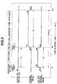
- the zero point is set, as illustrated in the time chart of Fig. 5.
- the testing gas suction pump 28 and the purge pump 29 are activated at all times so that the ambient gas, i.e., the atmosphere in the head cover 17 is sucked before the insertion of the hollow body 1 into the head cover 17, to purge the air passage from the head cover 17 to the testing conduit 24.
- the suction is made by both the purge pump 29 and the suction pump 28 so that the air passage is purged for a short time period, i.e., T3 (e.g., about 0.5 sec.), as indicated in Figs. 4 and 5.
- the purge solenoid valve 30 is closed so that the ambient gas in the head cover 17 is sucked exclusively by the suction pump 28 into the chamber, i.e., the conduit 24 being irradiated with the infrared ray.
- the ambient gas before the test i.e., the atmosphere in the test circumstance is flowing as it is into the conduit 24 so that the detected value to be outputted from the infrared detector 25, i.e., the ratio of absorption of the infrared ray by the atmosphere is adopted as the reference valve or the zero point. This occurs at time t1 of Figs. 4 and 5, and the concentration of the carbon dioxide in the atmosphere is set to the zero point.
- the injection nozzle head 6 is inserted by a predetermined stroke from the open end portion into the inside of the hollow body 1. Specifically, the injection nozzle head 6 is inserted so far as the position in which the atmosphere inlet passages 19 formed in the head cover 17 are not clogged by the expanded chuck 8 of the injection nozzle head 6 and in which the opening of the testing gas feed passage 13 of the top piece 9 comes close to the weld 14 between the head piece 2 and the body member 3.
- the hollow body 1 is moved forward together with the injection nozzle head 6, and its closed side end portion is inserted and set in position in the head cover 17.
- the hollow body 1 is inserted so far that the portion of its shoulder, as located more radially central than the weld 14, abuts against the radial ribs 20 formed in the head cover 17.
- no seal is established between the head cover 17 and the hollow body 1, but small clearances are left between the hollow body 1 and the inner face of the head cover 17.
- the chuck actuating air feeder 11 is activated to feed the pressurized air into the chuck 8, as located inside of the hollow body 1, to expand it radially.
- the air feeder 11 feeds the pressurized air through the pipe 12 to the chuck 8 so that the chuck 8 is radially expanded to push the body member 3 radially outward.
- the outer circumference of the chuck 8 comes into close contact with the body member 3 to seal the leading end portion of the hollow body 1.
- this hollow body 1 is fixed by the chuck 8 while forming the sealed space 7 at its leading end side.
- the solenoid valve 16 for feeding the testing gas is opened to feed the testing gas to the top piece 9 through the pipe 15.
- the sealed space 7, as formed at the leading end side of the hollow body 1 is fed with the pressurized testing gas for a predetermined time period T2 (e.g., about 0.4 to 0.8 sec.), as indicated in Figs. 4 and 5, through the testing gas feed passage 13 formed in the top piece 9, thereby to raise the internal pressure of the sealed space 7.
- T2 e.g., about 0.4 to 0.8 sec.
- the testing gas feeding pressure is preferably set to a level considering the internal pressure to be applied at the subsequent steps of filling the hollow body 1 with its content and retorting the content. Then, it is possible to detect even the container having such a defective welded or jointed portion at this testing step that the weld or joint might otherwise come out after the container has been filled with the content and sealed up.
- the testing gas is blown in the direction of radius of the hollow body 1 from the testing gas feed passage 13 so that its dynamic pressure does not act directly upon the metal foil 4 or the seal portion at the leading end side of the head piece 2 of the hollow body 1.
- the metal foil 4 acting as the seal is not broken by the feed of the testing gas.
- the suction is made from the suction hole 22 formed in the head cover 17, by the testing gas suction pump 28.
- the inside i.e., the hollow portion 18 of the head cover 17 is evacuated so that the ambient air is sucked from the inlet holes 19 to flow near the outer wall of the leading end portion of the hollow body 1, until it is fed together with the existing gas to the gas testing conduit 24 through the suction hole 22 and the suction pipe 21.
- the testing gas is forced into the hollow body 1, and the ambient gas in the head cover 17 is fed to the conduit 24.
- the portion close to the center than the weld 14 is in abutment against the head cover 17, but is enabled to retain the gas passage by the ribs 20 so that it will not obstruct the gas flow.
- the gas as sucked through the suction pipe 21, is fed to the gas testing conduit 24 so that it is diffused in the conduit 24 to lose its flow velocity. Moreover, the infrared ray is emitted toward the gas thus diffused in the conduit 24 and reaches the infrared detector 25. The absorption of the infrared ray depending upon the concentration of the testing gas, as contained in the diffused gas, is electrically picked up so that the change in the electric signal according to the concentration change of the testing gas is detected.
- a predetermined testing time period T1 e.g., about 0.8 sec.
- T1 a predetermined testing time period
- the value at the time when the testing gas concentration having leaked and contained in the ambient gas exceeds a dispersion region Ra at the atmospheric level and reaches a defective level region Rb to be detected, or the value at the time when the concentration of the testing gas having leaked after keeping the pressurization of the testing gas and the suction of the ambient gas for a constant time period reaches a peak is measured.
- the electric signal is outputted from the infrared detector 25 to the controller 26.
- the measured value of the testing gas concentration in the atmosphere has slight dispersion even in a indefective article, as illustrated in the dispersion region, i.e., the Ra region at the atmospheric level of Fig. 4.
- the dispersion region i.e., the Ra region at the atmospheric level of Fig. 4.
- the concentration of the testing gas in the sucked ambient gas rises.
- the detected value according to the concentration of the carbon dioxide gas reaches the defect deciding level, i.e., the Rb region, as illustrated in Fig. 4, so that a testing gas concentration over the dispersion of the indefective article.
- the testing gas concentration over the dispersion region of the atmospheric level of Fig. 4 is detected so that the electric signal on the basis of the concentration is outputted from the infrared detector 25.
- the ratio of the testing gas, as contained in the gas is detected on the basis of the electric signal by the controller 26 and is recorded as data in the controller 26.
- the data recorded at the leakage testing time and the data recorded as the reference value are compared to decide whether or not the concentration of the testing gas, as contained in the gas sucked at the testing time, is higher than the reference value.
- the gas leakage is detected on the basis of the relative value of the concentration of the testing gas on the basis of the electric signal, as outputted after the purge from the infrared detector 25, that is, the concentration of the testing gas in the atmosphere for the reference value, and the concentration of the testing gas in the sucked gas.
- no leakage is decided if the detected value belongs to the Ra region of Fig. 4, but a leakage is decided if the detected value belongs to the Rb region.
- the test is ended at a time t2, as indicated in Figs. 4 and 5.
- the controller 26 sets the concentration of a specific substance in theatmosphere at zero point and decides whether or not the article is defective, in dependence upon whether or not the concentration of the specific substance exceeds the Ra region of Fig. 4, i.e., the general concentration fluctuation range of the substance in the atmosphere. If the article is indefective, the detected value of the testing gas is kept within the fluctuation range in the dispersion (i.e., the Ra region) of the atmospheric level in Fig. 4. If the article is so defective as to have a leakage, on the other hand, the detected value of the testing gas reaches the defect deciding level (i.e., the Rb region) of Fig. 4.
- the defect deciding level i.e., the Rb region
- the testing gas as blown from the testing gas feed passage 13, is set to conform to the internal pressure or the like, as required of the hollow body 1, during the retorting operation. If the welding strength of the weld 14 is low, this weld 14 is broken by the pressure in the sealed space 7 so that the testing gas will leak to the outside. As a result, even the article having an incomplete weld can be detected as a defective one by this leakage test.
- the weld 14 at the shoulder portion of the hollow body 1 can be tested.
- the hollow body 1 has such an insufficient welding strength that it is insufficiently welded even if sealed, the insufficiently welded portion is broken by the internal pressure so that it can be handled as the defective article.
- the completely welded products are handled as conforming articles.
- the tested hollow body 1 is removed from the head cover 17 and the chuck 8. Simultaneously with this, the testing gas feeding solenoid valve 16 is closed, but the purge solenoid valve 30 is opened to increase the suction by the purge pump 29. As a result, the testing gas, as left at the previous testing time, is discharged out from the head cover 17 through the air passage in the gas detecting conduit 24 thereby to purge the air passage with the atmosphere.
- the indefective one is conveyed to a subsequent step of capping it or filling it with a content, whereas the defective one is discharged to the outside of the line by suitable means.
- the ambient gas blowing fan 23, as arranged in the vicinity of the head cover 17, is always acting to diffuse the ambient gas around the head cover 17 so that the concentration of the testing gas in the ambient gas is always held at a substantially constant level.
- T3 e.g., about 1.5 sec.
- a new zero point is set for testing the leakage of the subsequent hollow body 1 to be tested. Then, all the hollow bodies 1 are tested by repeating testing procedures similar to the aforementioned one.
- the leakage testing apparatus of this embodiment it is possible to promptly detect the presence/absence of the leaking portion, as including the test on whether or not the weld 14, i.e., the welded portion between the head piece 2 and the body member 3 of the empty hollow body 1 before filled with the content is sufficiently welded, so that all the products can be tested.
- the container as formed by welding (or joining) two or more parts, generally has such a leaking passage due to the insufficient weld (or joint) as is meandering or shaped into a labyrinth, and is hence difficult to detect its leakage.
- the leakage is detected by sucking and collecting the ambient gas around the hollow body 1 and by detecting the leakage by the concentration of the specific substance of the gas. As a result, the leakage can be reliably detected without depending upon the shape of the leaking portion. Since the leakage can be promptly detected, moreover, the testing operation can be speeded up to test all the articles manufactured.
- the leakage testing apparatus 5 is of the so-called "open type" to release the testing gas to the atmosphere, and the gas recovery means is desirably arranged by considering the working circumstance.
- the testing gas is exemplified by the carbon dioxide gas, for example, the gas, as having leaked, is caused to reside in the lower portion by the action of gravity due to the difference in the specific gravity from the atmosphere. It is, therefore, preferable to arranged the gas recovery means in that lower portion so that it may act with the leakage testing apparatus 5 to recover the testing gas. It is further preferable to recover the gas to be discharged from the suction pump.
- the leading end of the head piece 2 of the hollow body 1 to be tested in this embodiment is sealed exclusively with the metal foil 4.
- this metal foil 4 may be broken by the internal pressure applied to the hollow body 1, this hollow body 1 can be tested with a lid 31 being fitted on the leading end of the head piece 2, as shown in Fig. 3.
- the concentration of the testing gas, as contained in the external ambient gas may gradually rise as the leakage test of the hollow body 1 to be tested is repeated. Since the zero point is setting for each hollow body 1 to be tested, the testing gas concentration in the ambient gas far exceeds the reference value, if the leakage occurs, so that the leakage can be tested without fail.
- the means for measuring the concentration of the testing gas contained in the sucked gas is exemplified by the nondispersive infrared detector 25.
- the testing gas detecting apparatus can be exemplified by the gas chromatography or the Orsat analyzing apparatus, for example, and the component analyzing method can be exemplified by the apparatus employing the thermal conductivity method, the combustion heat method, the optical wave interference method, the electric conductivity method, the sealed specific gravity method, the gas balance method, the gas column method, the windmill method, the outflow method, the mass spectrometry, the sound wave method or the magnetic method.
- the detector should be adopted, when selected, as the most suitable one for the detection by considering the characteristics of the testing gas employed.
- the gas suction pump is exemplified by the testing gas suction pump 28 and the purge pump 29, which may be replaced by one pump. Then, upstream of this single pump, there may be arranged a valve for adjusting the flow rate to perform the suctions for the gas at the testing time and for the purge.
- the embodiment has been described in case the hollow body 1 made mainly of polypropylene (PP) is to be subjected to the leakage test.
- PP polypropylene
- the present invention should not be limited thereto but can be applied to an apparatus for testing the leakage of containers or hollow members of various shapes such as containers molded mainly of plastic materials such as polyethylene, polystyrene, polycarbonate, ABS resin or polyester, pouches formed of a film, or metallic containers or cans.
- the testing gas should not be limited the carbon dioxide gas but can be exemplified by the gas in the atmosphere such as oxygen or nitrogen, or such a rare gas as is little present in the atmosphere, such as helium or methane.
- the chuck 8 should not be limited to the pneumatic chuck which is expanded by the air pressure as in the embodiment, but may be any if it can be radially expanded to seal the inside of the hollow body 1.
- the specific embodiment is constructed such that the movement of the leading end of the hollow body 1, as accompanying the rise in the internal pressure, is checked by the abutment of the shoulder portion against the ribs 20, and such that the ribs 20 are prevented from pushing the weld 14.
- the construction may be made such that the weld is not pushed at the leakage testing time, or such that the movement of the hollow body 1 is checked by abutting against the leading end portion of the head piece 2.
- the hollow body 1 for the laminated tube is prepared by welding the head piece 2 to one end portion of the cylindrical body member 3.
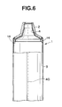
- This body member 3 is constructed, as shown in Fig. 6, by winding a laminated material cylindrically and by jointing (or welding) the two overlapped end portions of the laminated material by joint means (or weld means). If this joint (or weld) 40 of the body member 3 is defective, the content may possibly leak from the defective joint 40, and it is desired to test the leakage of the joint 40.
- a specific embodiment of the present invention to be described herein is constructed such that the leakage at this joint 40 is tested simultaneously with the aforementioned weld 14.
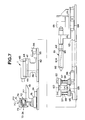
- Fig. 7 shows this entire construction schematically.
- an under case 41 for holding the hollow body 1 for the laminated tube to be subjected to the leakage test, generally in a horizontal position.
- This under case 41 is recessed on its upper face into a semicircle which has a slightly larger radius than the radius of curvature of the flexible hollow body 1 when this hollow body 1 is expanded into a cylindrical shape.
- These suction ports 44 are selectively given the communication with a not- shown but predetermined suction source through a discharge hole 46 which is formed through the inside of the under case 41.
- the hollow body 1 is placed and held on the ridges 45 by vacuum.
- a band-shaped ridge or a pillow block 47 extending in the circumferential direction.
- a plurality of air inlet holes 48 which extend through the under case 41 radially from the inner face of the arcuate recess 43.
- a number of grooves 49 which are axially extended to retain a gas passage between the inner face and the hollow body 1 to be placed thereon at the testing time.
- An upper case 50 forming a pair with that under case 41 is mounted to reciprocate between the position covering the under case 41 and the position away from the under case 41.
- an arcuate recess 51 which is generally identical to the aforementioned arcuate recess 43.
- a pillow block 52 which has the same shape as that of the aforementioned pillow block 47.
- a plurality of air inlet holes 53 which extend radially from the inner face of the arcuate recess 51.
- a number of grooves 54 In the inner face of the arcuate recess 51, there are further formed a number of grooves 54.
- each moving block 56 Over the bed 42 and at the left and right sides across the under case 41, there are arranged a pair of moving blocks 56 which individually engage with a rail 55 so that they can move back and forth.
- At the front and rear positions of each moving block 56 there are erected guide posts 57 so that the aforementioned upper case 50 is so mounted on those four guide posts 57 as to move up and down.
- On these guide posts 57 moreover, there are fitted coil springs 58 acting as a lifting mechanism so that the upper case 50 is usually held in a lifted position higher than the upper face of the aforementioned under case 41 by the coil springs 58.
- rollers 59 which are suspended by mounting plates 60 so that they may function as cam followers for lowering the upper case 50.
- the rollers 59 are so mounted on the mounting plates 60 as to rotate on the axis, as directed transversely of Fig. 10.
- the aforementioned under case 41 and upper case 50 are formed to have a length substantially equal to or slightly larger than that of the body member 3 of the hollow body 1 to be tested.
- a seal member 50A is fitted on the upper face 51 so as to keep the gas tightness on the individual mating faces.
- a mandrel 61 forming part of the injection mechanism of the present invention as to move back and forth toward the under case 41.
- This mandrel 61 is to be inserted into the hollow body 1 which is held by the individual cases 41 and 50.
- the mandrel 61 is formed into a shape, which is similar to the internal shape of the hollow body 1, and the length and external diameter of which are slightly smaller than those of the internal shape of the hollow body 1.
- a chuck 62 which is made elastically expansible/contractible.
- This chuck 62 is made of an annular elastic material such as rubber having a slightly smaller external diameter than the internal diameter of the body member 3, for example, and is constructed such that it is radially expanded, when axially compressed, to come into close contact with the inner circumference of the body member 3.
- mandrel 61 and chuck 62 are carried in a cantilever state, in which they protrude toward the under case 41, by a carriage 64 which can move back and forth along a rail 63 placed on the bed 42.
- a carriage 64 which can move back and forth along a rail 63 placed on the bed 42.
- an actuator 65 such as an air cylinder for pushing the chuck 62 axially.
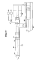
- a gas passage 61A is formed to extend axially through the insides of the mandrel 61 and the chuck 62, and a plurality of gas vents 66 are so formed all over the circumference in the leading end portion and the trailing end portion of the mandrel 61 as to communicate with that gas passage 61A. Moreover, this gas passage 61A is connected (as shown in Fig. 11) through a change-over valve 67 with a testing gas source 68 such as a gas cylinder and a vacuum source 69.
- a testing gas source 68 such as a gas cylinder and a vacuum source 69.
- a head cover 70 such that it can move back and forth toward the under case 41.
- this head cover 70 like the aforementioned head cover 17 shown in Fig. 2, there is formed therein a hollow portion 71 for receiving the leading end portion of the hollow body 1.
- the hollow portion 71 is formed into a slightly larger similar shape than the external shape of the leading end portion of the hollow body 1.
- a plurality of suction holes 72 which are opened in the portion corresponding to the shoulder portion of the hollow body 1.
- Another suction hole 172 is further formed in the top face of the head cover 70.
- the head cover 70 is carried on a carriage 75 which can move back and forth while engaging with a rail 74 which is arranged at the opposite side of the rail 63 for the mandrel 61 across the under case 41.
- a seal member 76 such as a seal ring for holding the gas tightness between the head cover 70 and the individual cases 41 and 50.
- the carriage 75 carrying the head cover 70 is equipped with means for moving up/down the upper case 50.
- the carriage 75 To the left and right sides of the carriage 75, as confronting the rollers 59, there are attached arms 77 which are projected toward the under case 41.
- the lower face of the leading end of each arm 77 is sloped upward to the leading end to provide a cam 78.
- the rollers 59 are guided downward by the cams 78 so that the upper case 50 goes down relative to the under case 41.
- the hollow body 1 to be tested is confined in the cylindrical portion defined by the cases 41 and 50 and is held gas-tight between the cases 41 and 50 by the chuck 62 inserted into the rear end portion of the cylindrical portion, and its leading end portion is inserted into the head cover 70.
- the cases 41, 50, the chuck 62 and the head cover 70 correspond to the hold mechanism of the present invention.
- the mandrel 61, the change-over valve 67 and the testing gas source 68 correspond to the injection mechanism of the present invention.
- the mechanism including the infrared detector of Fig. 1, as connected with the port 73 corresponds to the leakage detecting means.
- the vacuum source 69 and the purge pump correspond to the purge means of the present invention.
- the means for moving the upper case 50, the mandrel 61 and the head cover 70 back and forth toward the under case 41 may be exemplified by a suitable one, if necessary.
- the means can be constructed to move the upper case 50, the mandrel 61 or the head cover 70 back and forth by the actuator such as an air cylinder.
- the upper case 50, the mandrel 61 or the head cover 70 may be moved back and forth by a cam mechanism which is constructed by forming a cam groove in the moving or turning direction and by connecting a cam follower engaging with the cam groove to the upper case 50, the mandrel 61 or the head cover 70.
- the means for moving up/down the upper case 50, i.e., for opening/closing the cases 41 and 50 should not be limited to the cams 78 and the rollers 59 but may be constructed such that the cases 41 and 50 are directly opened/closed by the actuator such as an air cylinder.
- the hollow body 1 as conveyed from the manufacture process, is placed on the arcuate recess 43 of the under case 41 by a turret transfer machine or a robot (although not shown).
- the communication of the discharge hole 46 with the not-shown suction source is then opened so that the hollow body 1 is attracted on the individual suction ports 44 by the vacuum.
- the open end of the rear end side of the hollow body 1 is placed on the pillow block 47.
- the upper case 50 is moved toward the under case 41 and is positioned thereover.
- the carriage 64 carrying the mandrel 61 is moved toward the under case 41 so that the mandrel 61 and the chuck 62 are inserted into the hollow body 1 on the under case 41.
- the chuck 62 is not radially expanded yet so that it has no interference with the hollow body 1.
- the chuck 62 is positioned to extend inward and outward across the open end of the hollow body 1.
- the head cover 70 is carried toward the under case 41 by its carriage 75.
- the cams 78 are brought at first into engagement with the rollers 59 of the upper case 50 so that the upper case 50 is moved down through the rollers 59 as the head cover 70 advances.
- the hollow body 1 is accommodated/held in the cylindrical portion which is defined by the cylindrical recesses 43 and 51 of the cases 41 and 50.
- the head cover 70 advances to the forward end, it comes into abutment against the end faces of the under case 41 and the upper case 50 integrated, to accommodate the leading end portion of the hollow body 1 in its internal hollow portion 71 and to close the hollow portion 71 gas-tight.
- the chuck 62 is pushed in the axial direction by the actuator 65 so that the chuck 62 is radially expanded.
- the open end of the hollow body 1 is clamped between the chuck 62 and the upper and lower pillow blocks 47 and 52 so that it is closed gas-tightly.
- the chuck 62 is slightly projected from the open end of the hollow body 1 to have close contact with the inner circumference and the edge 3A of the open end of the hollow body 1 such that the edge 3A bites into the chuck 62 thereby to improve the gas-tightness.
- the suction is performed through the suction holes 72 and the suction hole 172 of the head cover 70 so that the gas (or air) around the hollow body 1 is carried to the detection mechanism, in which the concentration of the testing gas in the so-called “ambient gas” is measured to set the zero point with reference to the measured value.
- the testing gas e.g., the CO 2 gas
- the testing gas source 68 is fed from the testing gas source 68 through the change - over valve 67 to the mandrel 61, it is fed under pressure from the gas vents 66 to the inside of the hollow body 1.
- the vacuum for fixing the hollow body 1 in the under case 41.
- the gas to be fed to the detection mechanism by the suction from those suction holes 72 is only the atmosphere which has flown in from the air inlet holes 48 and 53 formed in the cases 41 and 50, respectively.
- the concentration of the testing gas, as achieved by the detection means such as the infrared detector has no meaningful change, and it is detected on the basis of the detected value that there is no leakage, namely, that the hollow body 1 is indefective.
- this testing gas is mixed into the gas flowing around the hollow body 1.
- the concentration of the testing gas as achieved by the detection means such as the infrared detector, rises over the reference value set to the zero point, so that the leakage of the testing gas is detected. In short, it is detected on the basis of the detected value that the hollow body 1 is defective.
- the air inlet holes 48 and 53 for guiding the atmosphere to the outer circumference of the hollow body 1 are formed near the pillow blocks 47 and 52 whereas the suction holes 72 and the suction hole 172 are formed in the head cover 70, and those air inlet holes 48 and 53 and the suction holes 72 and 172 are formed at the opposite sides in the longitudinal direction of the hollow body 1 so that the gas flows all over the outer circumference of the hollow body 1 without any residence.
- the testing gas never fails to be captured, if any leaking portion is present, so that an accurate test can be performed.
- the time period for feeding the testing gas is about 0.8 sec., for example, and the time period for detecting the testing gas is slightly longer and about 1.0 sec. so that the measurement of the concentration of the testing gas is ended after lapse of about 1.0 sec. from the start of the feed of the testing gas.
- the head cover 70 is retracted away from the under case 41. Out of engagement with the cams 78 or arms 77 and the rollers 59, therefore, the upper case 50 is lifted by the coil springs 58. Simultaneously with this, the actuator 65 having pushed the chuck 62 is released from its pushing action. As a result, the chuck 62 is radially contracted by its own elastic force to release the sealing of the inner and outer faces of the hollow body 1.
- the hollow body 1 When the hollow body 1 is thus released from its held state, it is attracted and held again in the under case 41 by the suction from the suction ports 44. Then, the head cover 70 and the mandrel 61 restore their initial positions. In this case, the mandrel 61 is extracted from the hollow body 1 so that the testing gas residing in the hollow body 1 is discharged from the inside of the hollow body 1. In accordance with this, the concentration of the testing gas around the testing apparatus gradually rises. In order to avoid this rise, e testing gas may be diffused by the fan, as described in the foregoing embodiment. For this diffusion, a fan may be placed in the vicinity of the head cover 70 to blow the wind toward (i.e., rightward of Fig. 7) the body portion of the hollow body 1.
- the inside of the hollow body 1 can be positively purged of the testing gas.
- the mandrel 61 is given the communication with the vacuum source 69 by the change-over valve 67 so that the testing gas is sucked from the inside of the hollow body 1 through the mandrel 61, and this mandrel 61 is extracted from the hollow body 1.
- the mandrel 61 is given the communication with the vacuum source 69 by the change-over valve 67 so that the testing gas is sucked from the inside of the hollow body 1 through the mandrel 61, and this mandrel 61 is extracted from the hollow body 1.
- the open end of the hollow body 1 to be clamped between the chuck 62 and the pillow blocks 47 and 52 is the portion to be weld-jointed when the hollow body 1 is to be constructed into a tube container. Therefore, the joint 40 near the open end is not subjected to any leakage test without any serious problem. In this embodiment, therefore, the hollow body 1 to be tested is enclosed in its entirety by the hold mechanism to establish the flow of the atmosphere around its entirety. As a result, it is possible to ensure the leakage test of the entire joint and to test the defect such as pin holes other than the joint.
- the means for injecting the pressurized testing gas into the hollow body 1 is exemplified by the mandrel 61 to be fitted at a small clearance on the inner face of the hollow body 1. It is, therefore, possible to prevent the expansion more than necessary of the hollow body 1 in advance even when the testing gas has a high injection pressure.
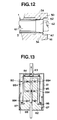
- a hold mechanism is constructed of a case 81 for accommodating a can body 80 and an end plate 82 to be attached to the open end of the can body 80.
- the case 81 is a container having one closed end as in the can body 80 to be tested, and is given larger external diameter and length than those of the can body 80.
- a suction hole 83 which has communication with a leakage testing mechanism composed mainly of a nondispersive infrared detector (although both are not shown).
- a leakage testing mechanism composed mainly of a nondispersive infrared detector (although both are not shown).
- an abutment plate 84 which abuts against the bottom portion of the can body 80 to position it and which has a groove for keeping a passage for the gas.
- the end plate 82 is a disc- shaped member having a diameter substantially equal to that of the open end of the case 81.
- an injection nozzle head (or a mandrel) 85 which has a slightly smaller external diameter than the internal diameter of the can body 80 and which is to be inserted into the can body 80.
- the outer circumference of the injection nozzle head 85 is equipped with a seal portion 86 for abutting against the open end of the can body 80 to establish a gas tight state.
- the seal portion 86 is made of a planar member of an elastic material such as rubber.
- the end plate 82 there are formed a plurality of inlet holes 87 which are extended through the thickness of the end plate 82 for introducing the atmosphere into the inside of the case 81.
- a testing gas feed passage 88 which is extended through the center portion of the injection nozzle head 85.
- This gas feed passage 88 is branched at its longitudinal intermediate portion into a plurality of branches which are opened as a plurality of gas injection holes 88a in the outer circumference of the injection nozzle head 85.
- this injection nozzle head 85 (or the mandrel) corresponds to the injection mechanism of the present invention.
- the injection nozzle head 85 is inserted into the inside of the can body 80, and the seal portion 86 is brought into close contact with the open end of the can body 80.
- the can body 80 is clamped between the abutment plate 84 and the seal portion 86 so that its inside and outside are isolated gas-tight from each other. If the suction is made in this state through the suction hole 83 by the leakage testing mechanism, the atmosphere is sucked from the inlet holes 87 into the inside of the case 81 so that it flows around the can body 80.
- the zero point is set by employing the concentration of the testing gas, as contained in the sucked gas, as the reference value.
- the testing gas such as the CO 2 gas is pressurized and fed from the gas feed passage 88 into the inside of the can body 80.
- the testing gas in the can body 80 will leak to the outside so that it is mixed with the atmosphere flowing around the can body 80 and carried to the leakage testing mechanism. As a result, the concentration of the testing gas to be detected rises, and it is decided that the can body 80 is defective. If the can body 80 has no defect, on the other hand, the detected value of the testing gas will not rise, and it is decided that the can body 80 is indefective.
- Fig. 14 schematically shows a leakage testing apparatus for a can lid 90.
- This can lid 90 also has a hollow shape having one closed end as in the can body 80 so that its testing apparatus has a basic construction similar to that of the apparatus shown in Fig. 13, with a slight difference in the size.
- the portions similar to those of the apparatus of Fig. 13 are designated by the common reference numerals, and their description will be omitted. Only one injection hole 88a is provided in the present embodiment, but a plurality of injection holes may be formed.
- the abutment plate 84 to be used in the apparatus shown in Fig. 13 or 14 may be any if it can position the can body 80 or the can lid 90 while retaining a gap for the gas flow between the end face of the case 81 and the end face of the can body 80 or the can lid 90 to be tested, as shown in Fig. 15A or 15B.
- the abutment plate 84 is exemplified by an annular disc having a number of radial ridges 84A.
- the abutment plate 84 is exemplified by an annular disc having a number of pawls 84B on its circumferential edge.
- the abutment plate 85 of either shape can hold the can body 80 or the can lid 90 while retaining the passage for the gas.
- the leakage of the gas can be detected, even in a small quantity, as the concentration change of a specific substance in the ambient gas, and is sucked as the ambient gas, as different from the operation to capture only the testing gas, and subjected to a qualitative analysis so that it can be detected in a high accuracy and at a high speed.
- the apparatus can be constructed as the so-called "open-type apparatus" so that it can be easily manufactured.
- the concentration of the testing gas in the ambient gas with no feed of the testing gas and the concentration of the testing gas, as contained in the ambient gas while the testing gas is being fed to the inside of the hollow body to be tested can be compared to decide that the hollow body has a leakage and to detect it as a defective when the concentration of the testing gas being fed is high.
- the so-called "open type leakage test” can be performed easily and accurately with reference to the ambient gas without providing any special testing chamber.
Landscapes
- Physics & Mathematics (AREA)
- General Physics & Mathematics (AREA)
- Examining Or Testing Airtightness (AREA)
Applications Claiming Priority (6)
| Application Number | Priority Date | Filing Date | Title |
|---|---|---|---|
| JP23136996 | 1996-08-13 | ||
| JP23136996 | 1996-08-13 | ||
| JP231369/96 | 1996-08-13 | ||
| JP18770597A JP3376250B2 (ja) | 1996-08-13 | 1997-06-27 | 中空部材の漏洩検査装置および方法 |
| JP18770597 | 1997-06-27 | ||
| JP187705/97 | 1997-06-27 |
Publications (3)
| Publication Number | Publication Date |
|---|---|
| EP0826954A2 true EP0826954A2 (fr) | 1998-03-04 |
| EP0826954A3 EP0826954A3 (fr) | 1999-02-03 |
| EP0826954B1 EP0826954B1 (fr) | 2004-03-31 |
Family
ID=26504514
Family Applications (1)
| Application Number | Title | Priority Date | Filing Date |
|---|---|---|---|
| EP97306088A Expired - Lifetime EP0826954B1 (fr) | 1996-08-13 | 1997-08-11 | Procédé et dispositif d'essai d'étanchéité d'un élément creux |
Country Status (5)
| Country | Link |
|---|---|
| US (1) | US5861547A (fr) |
| EP (1) | EP0826954B1 (fr) |
| JP (1) | JP3376250B2 (fr) |
| CA (1) | CA2211600C (fr) |
| DE (1) | DE69728332T2 (fr) |
Cited By (7)
| Publication number | Priority date | Publication date | Assignee | Title |
|---|---|---|---|---|
| WO2001046667A1 (fr) * | 1999-12-22 | 2001-06-28 | Inficon Gmbh | Procede d'exploitation d'un detecteur de fuites pelliculaire et detecteur de fuites pelliculaire correspondant pour mettre ledit procede en oeuvre |
| US6945092B2 (en) | 1999-12-22 | 2005-09-20 | Inficon Gmbh | Method for operating a film leak indicator and a corresponding film leak indicator for carrying out said method |
| GB2493009A (en) * | 2011-07-21 | 2013-01-23 | Packtester Ltd | Seal integrity detector for sealed packages |
| WO2019008169A1 (fr) * | 2017-07-06 | 2019-01-10 | Ateq | Procédé de détection de fuite d'une pièce creuse et installation pour la mise en œuvre d'un tel procédé |
| FR3068782A1 (fr) * | 2017-07-06 | 2019-01-11 | Ateq | Procede de detection de fuite d'une piece creuse et installation pour la mise en œuvre d'un tel procede |
| US11300472B2 (en) | 2017-11-16 | 2022-04-12 | Ateq | Installation and method for detecting and locating a leak in a fluid transport circuit, notably of an aircraft |
| US11906393B2 (en) | 2019-01-29 | 2024-02-20 | Ateq | Tracer gas leak detection system and corresponding use |
Families Citing this family (26)
| Publication number | Priority date | Publication date | Assignee | Title |
|---|---|---|---|---|
| US6439053B1 (en) * | 2000-09-13 | 2002-08-27 | Henry Alan Bobulski | Acoustic spectrometer apparatus and method for cavity geometry verification |
| US6393896B1 (en) * | 2000-10-31 | 2002-05-28 | Behavior Tech Computer Corporation | Test device for leakage-proof of a keyboard |
| DE10126458C2 (de) * | 2001-05-31 | 2003-06-12 | Daimler Chrysler Ag | Dichtheits- und Funktionsprüfung eines Sperrventils in einer pneumatischen Federung |
| EP1469294A4 (fr) * | 2001-12-14 | 2006-09-06 | Mitsui Mining & Smelting Co | Dispositif servant a detecter une fuite de liquide dans un reservoir |
| JP3698108B2 (ja) | 2002-02-20 | 2005-09-21 | 株式会社デンソー | 気密漏れ検査方法及び装置 |
| US6766259B2 (en) * | 2002-07-29 | 2004-07-20 | Baxter International Inc. | System and a method for detecting fiber damage in a dialyzer |
| US20050050943A1 (en) * | 2003-09-08 | 2005-03-10 | Tom Barber | Dry aerosol leak detection for dialyzers |
| WO2005043104A1 (fr) * | 2003-10-31 | 2005-05-12 | Mitsui Mining & Smelting Co., Ltd. | Detecteur de fuite de liquide dans un reservoir |
| JP2006105736A (ja) * | 2004-10-04 | 2006-04-20 | Toppan Printing Co Ltd | 密封容器の漏れ検出装置 |
| DE102004050762A1 (de) * | 2004-10-16 | 2006-04-20 | Inficon Gmbh | Verfahren zur Lecksuche |
| JP2006153635A (ja) * | 2004-11-29 | 2006-06-15 | Mitsui Mining & Smelting Co Ltd | タンク内液体の漏れ検知装置 |
| JP4734670B2 (ja) * | 2006-05-19 | 2011-07-27 | 独立行政法人産業技術総合研究所 | 高速ガス漏洩検知器 |
| JP5102155B2 (ja) * | 2008-09-03 | 2012-12-19 | 株式会社 スズキ技研 | リーク点検出器 |
| RU2392595C1 (ru) * | 2009-05-28 | 2010-06-20 | Федеральное Государственное Унитарное Предприятие "Государственный научно-производственный ракетно-космический центр "ЦСКБ-Прогресс" | Способ контроля герметичности |
| JP5635294B2 (ja) * | 2010-04-20 | 2014-12-03 | 株式会社初田製作所 | リーク測定方法及びリーク測定システム |
| RU2421700C1 (ru) * | 2010-04-30 | 2011-06-20 | Открытое акционерное общество "Ракетно-космическая корпорация "Энергия" имени С.П. Королева" | Способ определения негерметичности изделий |
| DE102010024134B4 (de) * | 2010-06-17 | 2012-07-12 | INPRO Innovationsgesellschaft für fortgeschrittene Produktionssysteme in der Fahrzeugindustrie mbH | Verfahren zum zerstörungsfreien Prüfen von mindestens teiloffenen hohlförmigen Bauteilen oder Systemkomponenten auf Dichtheit in der Serienproduktion |
| FR3000215B1 (fr) * | 2012-12-21 | 2016-02-05 | Aneolia | Dispositif et procede de test d'un echantillon, en particulier de discrimination d'un gaz d'un echantillon |
| JP6197893B2 (ja) * | 2016-02-03 | 2017-09-20 | 日本電産サンキョーシーエムアイ株式会社 | 筒状部材のクラック発見用検査装置 |
| JP6851953B2 (ja) * | 2017-10-30 | 2021-03-31 | アークレイ株式会社 | ポンプ駆動方法 |
| CN112888927A (zh) * | 2018-07-03 | 2021-06-01 | 英飞康公司 | 用于显示物质浓度数据的方法及相关设备 |
| CN112683470A (zh) * | 2020-12-31 | 2021-04-20 | 重庆诺伯斯自动化设备有限公司 | 一种能够缩短测试时间的气密测试方法及其设备 |
| JP2022158665A (ja) * | 2021-04-02 | 2022-10-17 | 日産自動車株式会社 | 防水コネクタ |
| CN113295343B (zh) * | 2021-04-21 | 2024-02-20 | 国核电站运行服务技术有限公司 | 容器检漏工艺试验装置及方法 |
| CN117147063B (zh) * | 2023-10-31 | 2024-01-09 | 泰安九洲金城机械有限公司 | 一种前桥检测装置 |
| CN118913536B (zh) * | 2024-10-08 | 2025-02-07 | 泰森日盛集团有限公司 | 一种柜门密封结构测试装置及测试方法 |
Family Cites Families (14)
| Publication number | Priority date | Publication date | Assignee | Title |
|---|---|---|---|---|
| US3423990A (en) * | 1967-07-25 | 1969-01-28 | Continental Can Co | Apparatus and method for detecting leaky cans |
| BE755369A (nl) * | 1969-08-27 | 1971-03-01 | Leer U K Ltd Van | Werkwijze en inrichting voor het op dichtheid onderzoeken van een voorwerp, zoals een vat, een afsluiting, een membraan enz. |
| US3762212A (en) * | 1971-07-15 | 1973-10-02 | Advanced Technologies Inc | Leak testing apparatus and methods |
| US3949596A (en) * | 1974-12-11 | 1976-04-13 | The United States Of America As Represented By The United States Energy Research And Development Administration | Leak test fixture and method for using same |
| GB2000300B (en) | 1977-06-27 | 1982-02-03 | Leybold Heraeus Gmbh & Co Kg | Method and apparatus for leak detection |
| JPS5459191A (en) * | 1977-10-19 | 1979-05-12 | Toshiba Corp | Method and apparatus for detection of minute leakage |
| JPS5651634A (en) * | 1979-10-04 | 1981-05-09 | Kato Seisakusho:Kk | Method and device for leak test |
| JPS5844325A (ja) * | 1981-09-10 | 1983-03-15 | Dainippon Printing Co Ltd | 容器の漏れ検査装置 |
| JPS60178332A (ja) * | 1984-02-27 | 1985-09-12 | Toshiba Corp | 漏洩検出装置 |
| US4754638A (en) * | 1986-05-23 | 1988-07-05 | Antares Engineering, Inc. | Apparatus and method for leak testing automotive wheel rims |
| SU1486823A1 (ru) * | 1987-03-09 | 1989-06-15 | Arkadij V Volosnikov | Устройство для герметизации тонкостенных бесфланцевых изделий. |
| US5163315A (en) * | 1990-07-10 | 1992-11-17 | Daikin Industries, Ltd. | Leak detecting method for vessels |
| CA2090283A1 (fr) * | 1992-02-28 | 1993-08-29 | Nobuyuki Hamanaka | Derives de l'acide phenoxyacetique |
| JPH0648373A (ja) * | 1992-07-31 | 1994-02-22 | Mitsubishi Heavy Ind Ltd | フラップ付き舵 |
-
1997
- 1997-06-27 JP JP18770597A patent/JP3376250B2/ja not_active Expired - Fee Related
- 1997-08-11 EP EP97306088A patent/EP0826954B1/fr not_active Expired - Lifetime
- 1997-08-11 DE DE69728332T patent/DE69728332T2/de not_active Expired - Fee Related
- 1997-08-12 US US08/909,876 patent/US5861547A/en not_active Expired - Fee Related
- 1997-08-13 CA CA002211600A patent/CA2211600C/fr not_active Expired - Fee Related
Cited By (8)
| Publication number | Priority date | Publication date | Assignee | Title |
|---|---|---|---|---|
| WO2001046667A1 (fr) * | 1999-12-22 | 2001-06-28 | Inficon Gmbh | Procede d'exploitation d'un detecteur de fuites pelliculaire et detecteur de fuites pelliculaire correspondant pour mettre ledit procede en oeuvre |
| US6945092B2 (en) | 1999-12-22 | 2005-09-20 | Inficon Gmbh | Method for operating a film leak indicator and a corresponding film leak indicator for carrying out said method |
| GB2493009A (en) * | 2011-07-21 | 2013-01-23 | Packtester Ltd | Seal integrity detector for sealed packages |
| WO2019008169A1 (fr) * | 2017-07-06 | 2019-01-10 | Ateq | Procédé de détection de fuite d'une pièce creuse et installation pour la mise en œuvre d'un tel procédé |
| FR3068782A1 (fr) * | 2017-07-06 | 2019-01-11 | Ateq | Procede de detection de fuite d'une piece creuse et installation pour la mise en œuvre d'un tel procede |
| US11719591B2 (en) | 2017-07-06 | 2023-08-08 | Ateq | Method for detecting leakage of a hollow component and installation for implementing such a method |
| US11300472B2 (en) | 2017-11-16 | 2022-04-12 | Ateq | Installation and method for detecting and locating a leak in a fluid transport circuit, notably of an aircraft |
| US11906393B2 (en) | 2019-01-29 | 2024-02-20 | Ateq | Tracer gas leak detection system and corresponding use |
Also Published As
| Publication number | Publication date |
|---|---|
| EP0826954A3 (fr) | 1999-02-03 |
| CA2211600A1 (fr) | 1998-02-13 |
| CA2211600C (fr) | 2001-02-06 |
| US5861547A (en) | 1999-01-19 |
| DE69728332T2 (de) | 2004-08-26 |
| JP3376250B2 (ja) | 2003-02-10 |
| DE69728332D1 (de) | 2004-05-06 |
| JPH10111209A (ja) | 1998-04-28 |
| EP0826954B1 (fr) | 2004-03-31 |
Similar Documents
| Publication | Publication Date | Title |
|---|---|---|
| US5861547A (en) | Apparatus for and method of testing leakage of hollow member | |
| EP0581551B1 (fr) | Procédé et dispositif d'essai d'objets en forme de sac | |
| AU715679B2 (en) | Method and apparatus for detecting leaks | |
| US5850036A (en) | Apparatus for leak testing vehicle wheels | |
| US4184362A (en) | Bottle leak tester | |
| CN106601315A (zh) | 一种燃料棒全自动氦检漏装置 | |
| US6289722B1 (en) | Helium leak tester for vehicle fuel tanks | |
| US5894868A (en) | Method for filling a hydrodynamic bearing | |
| CN102269641A (zh) | 软包装物品密封性检测装置和检测方法 | |
| CN215338750U (zh) | 气密性检测设备 | |
| CA2100739C (fr) | Mesurage de debit de fuite dans un contenant rempli de gaz | |
| JPS62112027A (ja) | 容器の漏洩検知方法 | |
| CN212300763U (zh) | 一种金属波纹管检漏设备 | |
| CN110954280A (zh) | 一种检漏装置 | |
| CN110231128B (zh) | 氦检漏机构 | |
| WO1999010721A1 (fr) | Epreuve d'etancheite | |
| CN110954277B (zh) | 一种检漏装置 | |
| JP3990584B2 (ja) | 紙カップ漏れ検査装置 | |
| CN212496401U (zh) | 热敏电阻温度传感器总装配设备 | |
| KR20190072982A (ko) | 캔 용기 누설검사장치 | |
| KR101857114B1 (ko) | 리크테스트를 위한 이송장치 | |
| JPH1194681A (ja) | 容器の漏洩検査装置 | |
| JP3453048B2 (ja) | 容器の漏洩検査装置 | |
| JP3590500B2 (ja) | ガス検知器検査装置 | |
| CN217191039U (zh) | 检测单元及锂电池自动检测系统 |
Legal Events
| Date | Code | Title | Description |
|---|---|---|---|
| PUAI | Public reference made under article 153(3) epc to a published international application that has entered the european phase |
Free format text: ORIGINAL CODE: 0009012 |
|
| 17P | Request for examination filed |
Effective date: 19970816 |
|
| AK | Designated contracting states |
Kind code of ref document: A2 Designated state(s): CH DE FR GB LI |
|
| PUAL | Search report despatched |
Free format text: ORIGINAL CODE: 0009013 |
|
| AK | Designated contracting states |
Kind code of ref document: A3 Designated state(s): AT BE CH DE DK ES FI FR GB GR IE IT LI LU MC NL PT SE |
|
| AKX | Designation fees paid |
Free format text: CH DE FR GB LI |
|
| 17Q | First examination report despatched |
Effective date: 20030319 |
|
| GRAP | Despatch of communication of intention to grant a patent |
Free format text: ORIGINAL CODE: EPIDOSNIGR1 |
|
| GRAS | Grant fee paid |
Free format text: ORIGINAL CODE: EPIDOSNIGR3 |
|
| GRAA | (expected) grant |
Free format text: ORIGINAL CODE: 0009210 |
|
| AK | Designated contracting states |
Kind code of ref document: B1 Designated state(s): CH DE FR GB LI |
|
| REG | Reference to a national code |
Ref country code: GB Ref legal event code: FG4D Ref country code: CH Ref legal event code: EP |
|
| REF | Corresponds to: |
Ref document number: 69728332 Country of ref document: DE Date of ref document: 20040506 Kind code of ref document: P |
|
| ET | Fr: translation filed | ||
| REG | Reference to a national code |
Ref country code: CH Ref legal event code: NV Representative=s name: CABINET GERMAIN & MAUREAU |
|
| PLBE | No opposition filed within time limit |
Free format text: ORIGINAL CODE: 0009261 |
|
| STAA | Information on the status of an ep patent application or granted ep patent |
Free format text: STATUS: NO OPPOSITION FILED WITHIN TIME LIMIT |
|
| 26N | No opposition filed |
Effective date: 20050104 |
|
| PGFP | Annual fee paid to national office [announced via postgrant information from national office to epo] |
Ref country code: FR Payment date: 20050711 Year of fee payment: 9 |
|
| PGFP | Annual fee paid to national office [announced via postgrant information from national office to epo] |
Ref country code: GB Payment date: 20050714 Year of fee payment: 9 |
|
| PGFP | Annual fee paid to national office [announced via postgrant information from national office to epo] |
Ref country code: DE Payment date: 20050715 Year of fee payment: 9 Ref country code: CH Payment date: 20050715 Year of fee payment: 9 |
|
| PG25 | Lapsed in a contracting state [announced via postgrant information from national office to epo] |
Ref country code: LI Free format text: LAPSE BECAUSE OF NON-PAYMENT OF DUE FEES Effective date: 20060831 Ref country code: CH Free format text: LAPSE BECAUSE OF NON-PAYMENT OF DUE FEES Effective date: 20060831 |
|
| PG25 | Lapsed in a contracting state [announced via postgrant information from national office to epo] |
Ref country code: DE Free format text: LAPSE BECAUSE OF NON-PAYMENT OF DUE FEES Effective date: 20070301 |
|
| REG | Reference to a national code |
Ref country code: CH Ref legal event code: PL |
|
| GBPC | Gb: european patent ceased through non-payment of renewal fee |
Effective date: 20060811 |
|
| REG | Reference to a national code |
Ref country code: FR Ref legal event code: ST Effective date: 20070430 |
|
| PG25 | Lapsed in a contracting state [announced via postgrant information from national office to epo] |
Ref country code: GB Free format text: LAPSE BECAUSE OF NON-PAYMENT OF DUE FEES Effective date: 20060811 |
|
| PG25 | Lapsed in a contracting state [announced via postgrant information from national office to epo] |
Ref country code: FR Free format text: LAPSE BECAUSE OF NON-PAYMENT OF DUE FEES Effective date: 20060831 |