EP0827006A2 - Dispositif de projection avec des moyens de séparation/synthèse des couleurs - Google Patents
Dispositif de projection avec des moyens de séparation/synthèse des couleurs Download PDFInfo
- Publication number
- EP0827006A2 EP0827006A2 EP97306671A EP97306671A EP0827006A2 EP 0827006 A2 EP0827006 A2 EP 0827006A2 EP 97306671 A EP97306671 A EP 97306671A EP 97306671 A EP97306671 A EP 97306671A EP 0827006 A2 EP0827006 A2 EP 0827006A2
- Authority
- EP
- European Patent Office
- Prior art keywords
- ray
- dielectric multilayer
- rays
- multilayer film
- projector apparatus
- Prior art date
- Legal status (The legal status is an assumption and is not a legal conclusion. Google has not performed a legal analysis and makes no representation as to the accuracy of the status listed.)
- Granted
Links
Images


Classifications
-
- H—ELECTRICITY
- H04—ELECTRIC COMMUNICATION TECHNIQUE
- H04N—PICTORIAL COMMUNICATION, e.g. TELEVISION
- H04N9/00—Details of colour television systems
- H04N9/12—Picture reproducers
- H04N9/31—Projection devices for colour picture display, e.g. using electronic spatial light modulators [ESLM]
- H04N9/3102—Projection devices for colour picture display, e.g. using electronic spatial light modulators [ESLM] using two-dimensional electronic spatial light modulators
- H04N9/3105—Projection devices for colour picture display, e.g. using electronic spatial light modulators [ESLM] using two-dimensional electronic spatial light modulators for displaying all colours simultaneously, e.g. by using two or more electronic spatial light modulators
Definitions
- This invention relates to a color separation/synthesis apparatus and to a projector apparatus.
- An embodiment of the invention concerns a projector apparatus using a plurality of reflective type spatial modulators.
- emitted light from a bright light source such as a xenon or metal halide lamp
- a spatial modulator to be spatially-modulated in accordance with a video signal, and then thus obtained light is enlarged and projected by means of a projection optical system.
- methods for representing a natural image (color image) considered on such a projector apparatus include a first method in which color information is assigned to each pixel (that is, pixels of three primary colors are prepared for each pixel of the video signal) and a second method in which color information is assigned to a display image in the time division scheme (that is, a red component, a green component, and a blue component of a color image are successively displayed with a triple frequency of a frame frequency.
- the aforementioned first method has a problem in which the resolution is deteriorated by respectively preparing the three pixels for pixels of the video signal
- the second method has another problem in which deterioration of images occurs due to the separation of colors accompanying the motion of a glance.
- Fig. 1 shows a general structure of a projector apparatus 1 using transmission type spatial modulators, out of such apparatuses.
- white light L1 emitted from a light source 2 is separated into a blue ray L2A, a green ray L2B, and a red ray L2C in a color separation section 3 to be spatially modulated in accordance with the respective color components of an image in corresponding spatial modulators 4A to 4C, and thus obtained blue component L3A, green component L3B and red component L3C of the color image light are synthesized in a color synthesis section 5 and thereafter the resultant color image light L4 is projected via a projection lens 6 to outside.
- FIGs. 2 and 3 show a general configuration of a projector apparatus 10 using reflective type spatial modulators, out of the aforementioned projector apparatuses.
- white light L10 emitted from a light source 11 is introduced via a beam splitter 12 into a color separation section 13 to be separated into three primary colors, and the obtained blue ray L11A, green ray L11B, and red ray L11C are spatially modulated respectively in corresponding spatial modulators 14A to 14C.
- color image light L13 is formed by synthesizing the blue component L12A, green component L12B, and red component L12C of the color image light emitted respectively from the spatial modulators 14A to 14C in a color separation synthesis section 13 and is projected to outside via a beam splitter 12 and a projection lens 15 in order.
- the white light L10 emitted from the light source 11 is separated into the blue ray L11A, the green ray L11B and the red ray L11C in a color separation section 21, which are then introduced via the respective beam splitters 22A to 22C into the corresponding spatial modulators 14A to 14C to be spatially modulated.
- the color image light L13 is formed by synthesizing the obtained blue component L12A, green component L12B, and red component L12C of the color image light in a color synthesis section 23 and is projected to outside via the projection lens 15.
- the same face side of the spatial modulators 14A to 14C can be used for the separation and synthesis of colors, so that the apparatus has advantage in that the whole apparatus can be downsized as compared with the apparatus using the transmission type spatial modulators 4A to 4C (Fig. 1).
- a two-color dielectric multilayer film (hereinafter, referred to simply as dielectric multilayer film) is ordinarily employed as color separation and synthesis means for incident light.
- Fig. 4 shows the configuration of a projector apparatus 30 using glass as a holding means for the dielectric multilayer film and a reflective type spatial modulation element.
- white light L20 from a light source 31 is introduced into a color separation/synthesis section 33 via a beam splitter 32 and is sequentially color-separated by first and second dielectric mirrors 36A and 36B composed by respectively forming dielectric multilayer films 35A and 35B on one side of glass plates 34A and 34B.
- blue ray L21A, a green ray L21B and red ray L21C obtained by the color separation are respectively introduced into corresponding first to third spatial modulators 37A to 37C to be spatially modulated in accordance with a video signal which is supplied.
- a blue component L22A, a green component L22B, and a red component L22C of color image light based on the video signal, which are emitted from the first to third spatial modulators 37A to 37C are synthesized by the first and second mirrors 36A and 36B in the color separation/synthesis section 33 and the obtained color image light L23 is emitted to outside via a projection lens 38.
- the projector apparatus 30 has problems that astigmatism occurs in component rays (red and green rays) of the white light L20 transmitted through the first and second dielectric mirror 36A and 36B due to the width of the first or second dielectric mirror 36A or 36B, and on the other hand, aberration occurs in component rays (blue and green rays) of the white light L20 reflected from the first or second dielectric mirror 36A or 36B due to stress-strain.
- a tradeoff relation between the stigmatism due to the width of the first or second dielectric mirrors 36A and 36B and the aberration due to stress-strain has a problem in that it is difficult to obtain highly resolution images as projected images.
- Fig. 5 in which the same reference numerals are applied to parts corresponding to Fig. 4, there is a way to use glass blocks 42A to 42C as a holing means for dielectric multilayer films 41A and 41B.
- the way has advantage in which the stress can be reduced as compared with a case of using a glass plate as a holding means for dielectric multilayer film and also has advantage in which the length of an optical path to the projection lends 38 can be shortened.
- Figs. 6 and 7, in which the same reference numerals are applied to parts corresponding to Fig. 5, show the configuration of a projector apparatus using spatial modulators in which it is necessary to unify the number of reflections (all to odd or even) during the synthesis of colors.
- projector apparatuses 40, 50, and 60 using glass blocks 42A to 42C or 60A to 60D as a holding means for such dielectric multilayer films 41A and 41B have problems in that the large glass blocks 42A to 42C and 60A to 60D are heavy and expensive, and also have an essential problem in that the color purity of separated and formed blue ray L21A, green ray L21B, and red ray L21C is insufficient.
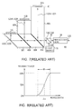
- the wavelength characteristic of a dielectric multilayer film generally has a certain degree of rising width "W" as shown in Fig. 8, and in the case where the white light is irradiated to the dielectric multilayer film with an incidence angle of 45°, the component rays of the wavelength range of intermediate colors included in the white light L20 are mixed with the transmitted light and reflected light of the dielectric multilayer films 41A to 41C (Figs. 5 to 7) because the rising width "W" for the white light L20 incident to the dielectric multilayer films 41A to 41C having both sides in contact with glass blocks 42A to 42C or 60A to 60D (Figs.
- the projector apparatuses 50 and 60 using spatial modulators 51A to 51C with the need for unifying the number of reflections of individual colors during the color synthesis as shown in Figs. 6 and 7, have problems of difficulty in the downsizing of the whole apparatus and the simplification of a configuration because an additional mirror 52 (Fig. 6) is required or large-sized glass blocks 60A to 60D of the color separation/synthesis section 61 (Fig. 7) are required as compared with the projector apparatus 40 (Fig. 5) using spatial modulators 37A to 37C (Fig. 5) without need for unifying the number of reflections.
- the narrower is the raising width "W" (Fig. 7) for the incident light of the dielectric multilayer films 41A and 41B
- the incidence angle ⁇ 1 of the incident light for the dielectric multilayer films 72A and 72B seems to be smaller than 45° as shown in Fig. 9 in which the same reference numerals are applied to parts corresponding to Fig. 5.
- the method has advantage in that the color purity of projected images can be improved and moreover the size of the glass blocks 81A to 81C can be small in comparison with a simple usage described in Fig. 9 because the incidence angle ⁇ 2 to the respective dielectric multilayer films 82A and 82B can be set to about 30°. This reason is that, as can be seen from Figs. 11A and 11B, the volume of a glass block can be reduced to half by the reflection of a transmitted ray even for the same length of an optical path.
- the wavelength characteristic of the second dielectric multilayer film 82B is such as shown in Fig. 8.
- 50% of the light is reflected from the second dielectric multilayer film 82B and enters the second spatial modulator 37B and the rest 50% is transmitted through the second dielectric multilayer film 82B and enters the third spatial modulator 37C.
- the two pieces of light are respectively reflected from the corresponding second or third spatial modulator 37B or 37C.
- a gap 83 is provided between the glass block 81B and the glass block 81A in order to totally reflect green ray L22B reflected from the second dielectric multilayer film 82B inside the glass clock 81B, but if the gap 83 is not adequately small, there are problems that astigmatism occurs and the slenderness ratio of a projected image changes.
- An embodiment of this invention as described herein seeks to provide a small-sized and light-weight projector apparatus capable of projecting an image of high picture quality.
- An embodiment of the present invention provides a projector apparatus of which a color separation/synthesis section comprises a glass block body composed of a plurality of glass blocks combined together in such a manner that the corresponding sides are in close contact with each other and a plurality of dielectric multilayer films respectively disposed between predetermined glass blocks for respectively separating corresponding component rays of white light included in the incident light and then reflecting or transmitting the component rays in predetermined entering directions to the corresponding spatial modulators, and for synthesizing the emitted rays from the plurality of corresponding spatial modulators and then projecting it in predetermined directions.
- the shapes of glass blocks are respectively selected so that unnecessary rays generated by reflecting or transmitting the reflected rays at the corresponding dielectric multilayer films for transmitting or reflecting the reflected rays emitted from the respective spatial modulators can not travel toward the reflective surface of any of spatial modulators and so that the reflected rays are reflected or transmitted at the corresponding dielectric multilayer films and then can first enter the surface of the glass block body with the incidence angle less than 30°.
- numeral 90 shows a projector according to a first embodiment as a whole, in which white light L40 emitted from a light source not shown in the back-to-surface direction of paper is introduced via a beam splitter 91 into a color separation/synthesis section 92 to be color-separated, and then thus obtained blue ray L41A, green ray L41B and red ray L41C respectively enter surfaces of corresponding first to third reflective type spatial modulators 93A to 93C with a slight slant in the back-to-surface direction of paper.
- first to third spatial modulators 93A to 93C corresponding to the pixel array (e.g., 848 X 600) of respectively supplied image data, minute mirror surface elements of about 16 ⁇ m squares are disposed in the form of a plane to thereby form reflective surfaces.
- the first to third spatial modulators 93A to 93C respectively comprise pixels of image data (i.e., mirror surface elements) and frame memories in which a plurality of memory cells is disposed corresponding the pixels.
- the frame memory is so arranged that data signals according to the image data respectively corresponding to individual frames are successively supplied to each memory cell thereof and each mirror surface element of the first to third spatial modulators 93A to 93C is so arranged as to be slant at +10° from the neutral position shown by dotted lines in a predetermined direction as shown in Fig. 13A when the corresponding memory cell changing in accordance with the data signal is in the ON state (i.e., valid as a pixel), and on the other hand, to be slant at -10° from the neutral position shown by dotted lines in a predetermined direction as shown in Fig. 13B when the memory cell is in the OFF state (i.e., invalid as a pixel).
- the mirror surface elements corresponding to pixels of the blue color component of a frame image become in the ON state to reflect the blue ray L41A incident thereto in a first direction parallel to the paper of Fig. 12, whereas other mirror surface elements become in the OFF state to reflect the blue ray L41A incident thereto in a different direction from the first direction.
- the mirror surface elements corresponding to pixels of the green color component of a frame image become in the ON state to reflect the green ray L41B incident thereto in a second direction parallel to the paper of Fig. 12, whereas other mirror surface elements become in the OFF state to reflect the green ray L41B incident thereto in a different direction from the second direction.
- the third spatial modulator 93C only the mirror surface elements corresponding to pixels of the red color component of a frame image become in the ON state to reflect the red ray L41C incident thereto in a third direction parallel to the paper of Fig. 12, whereas other mirror surface elements become in the OFF state to reflect the red ray L41C incident thereto in a different direction from the third direction.
- the blue component L42A, the green component L42B and the red component L42C of color image light on the basis of the image data are respectively emitted from the first to the third spatial modulators 93A to 93C in the first to the third direction parallel to the paper of Fig. 12, which are synthesized at the color separation/synthesis section 92. Then, thus obtained color image light L43 is projected to the outside via the beam splitter 91 and a projection lens 94 in order.
- the projector apparatus 90 irradiates color image light 43 emitted from the projection lends 94 so as to project images based on the image data, on a screen (not shown) disposed on the optical axis of the projection lens 94.
- the color separation/synthesis section 92 comprises a first glass block 100 having a square-shaped bottom, a second glass block 101 having a pentagonal bottom and a third glass block 102 having a triangle bottom, in which the first to third glass blocks 100 to 103 are combined in such a manner that a first side 100A of the first glass block 100 and a first side 101A of the second glass block 101 are in close contact with each other and a second side 101B of the second glass block 101 and a first side 102A of the third glass block 102 are in close contact with each other.
- the glass block body is constituted.
- a first dielectric multilayer film 103A which allows component rays having the wavelength range longer than that of blue light to be transmitted is laminated, whereas a second dielectric multilayer film 103B which allows component rays having the wavelength range longer than that of green light to be transmitted is laminated on the second side 101B of the second glass block 101.
- the blue component (blue ray L41A) of the white light L40 which enters thereto via the beam splitter 91 is obtained by the color separation of the white light L40 at the first dielectric multilayer film 103A and allowed to be totally reflected from the second and third sides 100B and 100C of the first glass block 100 in order and to enter the reflective surface of the first spatial modulator 93A through the first glass block 100
- the green component (green ray L41B) of the white light L40 transmitted through the first dielectric multilayer film 103A is allowed to be reflected from the second dielectric multilayer film 103B and to enter the reflective surface of the second spatial modulator 93B through the second glass block 101
- the red component (red ray L41C) of the white light L40 transmitted through the second dielectric multilayer film 103B is allowed to be totally reflected from the second side 102B of the third glass block 102 and to enter the reflective surface of the third spatial modulator 93C through the third glass block
- the red component ray L42C of the color image light emitted from the third spatial modulator 93C and the green component ray L42B of the color image light emitted from the second spatial modulator 93B are synthesized at the second dielectric multilayer film 103B, and then the obtained synthesized ray and the blue component ray L42A of the color image light emitted from the first spatial modulator 93A are synthesized at the first dielectric multilayer film 103A, in order to form the aforementioned color image light L43, and the light L43 is delivered to the projection lens 94 via the beam splitter 91 as described above.
- the shapes of the first to third glass blocks 100 to 102 are selected so that neither a ray L50 (hereinafter, referred to as first unnecessary ray) generated by transmitting or reflecting rays, which are respectively emitted from the first to third spatial modulators 93A to 93C and which are to be reflected from or transmitted through the first dielectric multilayer film 103A, through or from the first dielectric multilayer film 103A nor a ray L51 (hereinafter, referred to as second unnecessary ray) generated by transmitting or reflecting rays, which are respectively emitted from the third spatial modulators 93B and 93C and are which are to be reflected from or transmitted through the second dielectric multilayer film 103B, through or from the second dielectric multilayer film 103B travels toward the reflective surface of the first to third spatial modulators 93A to 93C, and the first to fourth rays L50 to L53 can first enter the surface of the first to third spatial modulators 93A to 93C
- the color separation/synthesis section 92 about 90% of the first and second unnecessary rays L50 and L52 can be emitted outside the first to third glass blocks 100 to 102 without special processing because the first and second unnecessary rays L50 and L52 first enter the surface of the first to third glass block 100 to 102 with the incidence angle ⁇ 3 or ⁇ 4 less than 30°, and the first and second unnecessary rays L50 and L51 emitted to outside the first to third glass blocks 100 to 102 are preventable from thereafter entering any reflective surface of the spatial modulators 93A to 93C because neither the first nor second unnecessary L50 and L51 travels toward any reflective surface of the first to third spatial modulators 93A to 93C.
- the first glass block 100 has a selected gradient of the first side 100A with respect to the second side 100B so that the white light L40 can enter the first dielectric multilayer film 103A with an incidence angle ⁇ 5 of about 30°
- the second glass block 101 has a selected gradient of the second side 101B with respect to the first side 101A so that a ray transmitted through the first dielectric multilayer film 103A can enter the second dielectric multilayer film 103B with an incidence angle ⁇ 6 of about 30°.
- the color separation/synthesis section 92 the wavelength characteristic of the first and second dielectric multilayer films 103A and 103B for incident light can be improved in comparison with a case where light enters the first and second dielectric multilayer films 103A and 103B with an incidence angle of 45°.
- the color purity of projection images can be enhanced.
- the white light L40 emitted from the light source enters the color separation/synthesis section 92 via the beam splitter 91.
- the blue component of the incident white light L40 is obtained by the color separation of the white light L40 at the first dielectric multilayer film 103A and the obtained blue ray L41A is irradiated on the reflective surface of the first spatial modulator 93A through the first glass block 100
- the green and red components of the white light L40 are obtained by the color separation at the second dielectric multilayer film 103B
- the obtained green ray L41B is irradiated on the reflective surface of the second spatial modulator 93B through the second glass block 101
- the obtained red ray L41C is irradiated on the reflective surface of the third spatial modulator 93C through the third glass block 102.
- the blue ray L41A, green ray L41B and red ray L41C respectively irradiated on the reflective surfaces of the first to third spatial modulators 93A to 93C are spatially modulated at the corresponding first to third spatial modulators 93A to 93C in accordance with image data which is supplied, respectively.
- the red component L42C and the green component L42B of the color image light obtained based on the image data are synthesized on the second dielectric multilayer film 103B of the color separation/synthesis section 92 and the obtained synthesized light and the blue component L42A of the color image light are synthesized on the first dielectric multilayer film 103A of the color separation/synthesis section 92.
- color image light L43 is emitted to the outside via the beam splitter 91 and the projection lens 94 in order and thus a color image based on the image data which is supplied is projected onto a screen disposed on the optical axis of the projection lens 94.
- the shapes of the first to third glass blocks 100 to 102 of the color separation/synthesis section 92 are selected so that the first and second unnecessary rays L50 and L51 transmitted through or reflected from the first and second dielectric multilayer films 103A and 103B do not travel toward any reflective surface of the first to third spatial modulators 93A and 93B and moreover the first and second unnecessary rays L50 and L51 first enter the surface of the first to third glass block 100 to 102 with the incidence angles ⁇ 3 or ⁇ 4 less than 30°.
- the first and second unnecessary rays L50 and L51 are preventable from entering the reflective surfaces of the first and third spatial modulators 93A to 93C almost surely and as a result the deterioration of projected images in contrast and color purity originating from scattering or the like which occurs when the first and second unnecessary rays L50 and L51 enter the reflective surfaces of the spatial modulators 93A to 93C can be prevented in advance.
- the incidence angles ⁇ 5 and ⁇ 6 of the white light L40 which enters the first and second dielectric multilayer films 103A and 103B are selected to about 30° with respect to the first and second dielectric multilayer films 103A and 103B, the wavelength characteristics for the first and second dielectric multilayer films 103A and 103B can be improved and as a result the color purity of projected images can be enhanced.
- the whole apparatus can be downsized and the configuration thereof can be simplified to such an extent.
- the present invention can contribute to the downsizing of a projector apparatus.
- the shapes of the first to third glass blocks 100 to 102 of the color separation/synthesis section 92 are selected so that neither first unnecessary ray L50 which is emitted from the first or third spatial modulator 93A or 93C and is transmitted through or reflected from the first dielectric multi-layer film 103A nor second unnecessary ray L51 which is emitted from the second or third spatial modulator 93B or 93C and is transmitted through or reflected from the second dielectric multilayer film 103B does not travel toward any reflective surface of the first to third spatial modulators 93A to 93C, and the first and second unnecessary rays L50 and L51, after being transmitted through or reflected from the first or second dielectric mulilayer film 103A or 103B, first enter the surface of the first to third glass blocks 100 to 102 with the incidence angle ⁇ 3 or ⁇ 4 less than 30°.
- ⁇ 3 or ⁇ 4 less than 30°
- Fig. 14 in which the same reference numerals are applied to parts corresponding to those of Fig. 12, shows a projector apparatus 110 according to a second embodiment and is composed as with the projector apparatus 90 (Fig. 12) of the first embodiment except that a third dielectric multilayer film 112 is formed on a third side 102C of the third glass block 102 in a color separation/synthesis section 111, in parallel with and opposed to the reflective surface of the third spatial modulator 93C.
- the third dielectric multilayer film 112 a film having rising wavelength longer than that of the second dielectric multilayer film 103B is used.
- the red ray 41C transmitted through the second dielectric multilayer film 103B enters the third dielectric multilayer film 112 with an incidence angle of almost 0°, the yellow component included in the red component can be almost surely removed and thus the red ray L41C having high color purity can enter the surface of the third spatial modulator 93C.
- the red ray L41C transmitted through the second dielectric multilayer film 103B of the color separation/synthesis section 111 is allowed to enter the reflective surface of the third spatial modulator 93C after the removal of the yellow component at the third dielectric multilayer film 112.
- the projector apparatus 110 since the red ray L41C having high color purity can enter the reflective surface of the third spatial modulator 93C as mentioned above, the color purity of the red component L42C of color image light emitted from the third spatial modulator 93C can be enhanced. Thus, the projector apparatus can project images having high color purity.
- the provision of a dielectric multilayer film on the surface of a glass block of the color separation/synthesis has a merit in the enhancement of color purity, however rays reflected from the dielectric multilayer film are apt to become unnecessary rays, and accordingly absorption filters are often employed usually in place of dielectric multi-layer films.
- this method has a problem of lower transmittance in a desired range of wavelength.
- the shapes of the first to third glass blocks 100 to 102 are selected so that the first and second unnecessary rays L50 and L51 do not travel toward any reflective surface of the first to third spatial modulators 93A to 93C and the first and second unnecessary rays L50 and L51 first respectively enter the surfaces of the first to third glass blocks 100 to 102 with the incidence angle ⁇ 3 and ⁇ 4 less than 30° as mentioned above, the influence of unnecessary rays emitted from the third dielectric multilayer film 112 is small and consequently an improvement in the color purity of projected images by the dielectric multilayer film 112 is implementable as mentioned above.
- the third dielectric multi-layer film 112 of rising wave length slightly longer than that of the second dielectric multilayer film 101B is provided on the third side 102C of the third glass block 102 in the color separation/synthesis section 111 employed for the projector apparatus 90 (Fig. 12) according to the first embodiment, so that the color purity of projected images can be enhanced and thus a small-sized and light-weight projector apparatus capable of projecting images of high image quality can be realized.
- the aforementioned first and second embodiments of the present invention apply to the projector apparatus 90 or 110 composed as shown in Fig. 12 or 14.
- the present invention is not limited thereto.
- the present invention is applicable to projector apparatuses of other various configurations, in brief, only if they are so arranged as to separate white light emitted from a light source into a plurality of component rays having a wavelength range in a color separation/synthesis section, spatially modulate the respective component rays in accordance with supplied image data in individual different reflective type spatial modulators and thereafter synthesize and emit the rays emitted from the respective spatial modulators at the color separation/synthesis section.
- the color separation/synthesis sections comprises the first to third blocks of such shapes as shown in Figs. 12 and 14, however, the present invention is not limited thereto and a shape of each glass block can be of others or a color separation/synthesis section can comprise four or more glass blocks.
- shapes and the number of glass blocks constituting the glass block body can be others only if a glass block body is composed by combining a plurality of glass blocks in such a manner as to bring the corresponding blocks into close contact with each other.
- the incident white light L20 is divided into three primary colors of a blue ray L41A, a green ray L41B and a red ray L41C, however the present invention is not limited thereto and the white light L20 can be separated into greater number of component rays.
- the dielectric multilayer film 112 is provided only on the third side 102C of the third glass block 102 which is opposite to the reflective surface of the third spatial modulator 93C, however, the present invention is not limited thereto and a dielectric multilayer film having a rising wavelength shorter than that of the first dielectric multilayer 103A can be provided also on the fourth side 100D of the first glass block 100 which is opposite to the reflective surface of the first spatial modulator 93A.
- one or more dielectric multilayer films having the respective predetermined wavelength characteristics are provided on surfaces of the glass block.
- reflective type modulators forming a projection scheme based on the difference in the reflection direction of a pixel unit are applied as the first to third spatial modulators 93A to 93C, however, the present invention is not limited thereto and reflective type spatial modulators forming a projection scheme based on the difference in reflection state such as reflectivity, diffusive reflection or polarization can be employed.
- a color separation/synthesis section of a projector apparatus comprises: a glass block body composed of a plurality of glass blocks combined together in such a manner that the corresponding sides are in close contact with each other; and a plurality of dielectric multilayer films respectively disposed between predetermined glass blocks, for separating corresponding component rays of white light individually included in incident light and reflecting or transmitting the respective corresponding component rays in predetermined entering directions to the corresponding spatial modulators and for synthesizing the rays emitted from the plurality of corresponding spatial modulators and emitting the resultant light in a predetermined direction.
- And forms of individual glass blocks are respectively chosen so that unnecessary rays generated by the reflection or transmission of reflected rays from respective spatial modulators at the corresponding dielectric multilayer films to be transmitted through or reflected from do not travel toward the reflective surface of any of spatial modulators and moreover at not greater incidence angle than 30 [degree] enter the surface of a glass block body reached first after the reflection or transmission at the corresponding dielectric multilayer film, so that the color purity and contrast of projected images can be enhanced and thus a small-sized and light-weight projector apparatus enabling images of high image quality to be projected can be realized.
- the shapes of the first to third glass blocks 100 to 102 are chosen so that all emitted rays (i.e., blue component L42A, green component L42B and red component L42C of color image light) which have entered the glass block body composed of the first to third glass blocks 100 to 102 from the first to third spatial modulators 93A to 93C are reflected odd times inside the glass block body, however the present invention is not limited thereto and the shapes of the first to third glass blocks 100 to 102 can be chosen so that all emitted rays L42A to L42C from the first to third spatial modulators 93A to 93C are reflected even times inside the glass block body composed of the first to third glass blocks 100 to 102.
Landscapes
- Engineering & Computer Science (AREA)
- Multimedia (AREA)
- Signal Processing (AREA)
- Projection Apparatus (AREA)
- Mechanical Light Control Or Optical Switches (AREA)
- Transforming Electric Information Into Light Information (AREA)
- Devices For Indicating Variable Information By Combining Individual Elements (AREA)
Applications Claiming Priority (3)
| Application Number | Priority Date | Filing Date | Title |
|---|---|---|---|
| JP25091896A JP3557317B2 (ja) | 1996-09-02 | 1996-09-02 | プロジエクタ装置及び色分離合成装置 |
| JP250918/96 | 1996-09-02 | ||
| JP25091896 | 1996-09-02 |
Publications (3)
| Publication Number | Publication Date |
|---|---|
| EP0827006A2 true EP0827006A2 (fr) | 1998-03-04 |
| EP0827006A3 EP0827006A3 (fr) | 1999-04-21 |
| EP0827006B1 EP0827006B1 (fr) | 2004-08-18 |
Family
ID=17214964
Family Applications (1)
| Application Number | Title | Priority Date | Filing Date |
|---|---|---|---|
| EP97306671A Expired - Lifetime EP0827006B1 (fr) | 1996-09-02 | 1997-08-29 | Dispositif de projection avec des moyens de séparation/synthèse des couleurs |
Country Status (5)
| Country | Link |
|---|---|
| US (1) | US6089717A (fr) |
| EP (1) | EP0827006B1 (fr) |
| JP (1) | JP3557317B2 (fr) |
| CA (1) | CA2214059A1 (fr) |
| DE (1) | DE69730282T2 (fr) |
Cited By (1)
| Publication number | Priority date | Publication date | Assignee | Title |
|---|---|---|---|---|
| EP1585344B1 (fr) * | 1998-09-29 | 2013-05-22 | Sony Corporation | Dispositif d'affichage de type projecteur |
Families Citing this family (49)
| Publication number | Priority date | Publication date | Assignee | Title |
|---|---|---|---|---|
| US6513934B1 (en) * | 1999-02-17 | 2003-02-04 | Canon Kabushiki Kaisha | Projection apparatus and observation apparatus |
| US7306338B2 (en) | 1999-07-28 | 2007-12-11 | Moxtek, Inc | Image projection system with a polarizing beam splitter |
| US6585378B2 (en) | 2001-03-20 | 2003-07-01 | Eastman Kodak Company | Digital cinema projector |
| US6909473B2 (en) * | 2002-01-07 | 2005-06-21 | Eastman Kodak Company | Display apparatus and method |
| US7061561B2 (en) * | 2002-01-07 | 2006-06-13 | Moxtek, Inc. | System for creating a patterned polarization compensator |
| US6808269B2 (en) * | 2002-01-16 | 2004-10-26 | Eastman Kodak Company | Projection apparatus using spatial light modulator |
| US6676260B2 (en) | 2002-04-25 | 2004-01-13 | Eastman Kodak Company | Projection apparatus using spatial light modulator with relay lens and dichroic combiner |
| US6786600B2 (en) * | 2002-05-01 | 2004-09-07 | Shamir Optical Industry | Methods for generating a progressive surface and for production of multifocal progressive lenses |
| US6648475B1 (en) | 2002-05-20 | 2003-11-18 | Eastman Kodak Company | Method and apparatus for increasing color gamut of a display |
| US6805445B2 (en) | 2002-06-05 | 2004-10-19 | Eastman Kodak Company | Projection display using a wire grid polarization beamsplitter with compensator |
| US6736514B2 (en) * | 2002-06-21 | 2004-05-18 | Eastman Kodak Company | Imaging apparatus for increased color gamut using dual spatial light modulators |
| US6809873B2 (en) * | 2002-09-09 | 2004-10-26 | Eastman Kodak Company | Color illumination system for spatial light modulators using multiple double telecentric relays |
| US6769772B2 (en) * | 2002-10-11 | 2004-08-03 | Eastman Kodak Company | Six color display apparatus having increased color gamut |
| US6802613B2 (en) * | 2002-10-16 | 2004-10-12 | Eastman Kodak Company | Broad gamut color display apparatus using an electromechanical grating device |
| US6807010B2 (en) * | 2002-11-13 | 2004-10-19 | Eastman Kodak Company | Projection display apparatus having both incoherent and laser light sources |
| US20040150794A1 (en) * | 2003-01-30 | 2004-08-05 | Eastman Kodak Company | Projector with camcorder defeat |
| US6758565B1 (en) | 2003-03-20 | 2004-07-06 | Eastman Kodak Company | Projection apparatus using telecentric optics |
| US7221759B2 (en) * | 2003-03-27 | 2007-05-22 | Eastman Kodak Company | Projector with enhanced security camcorder defeat |
| US6839181B1 (en) * | 2003-06-25 | 2005-01-04 | Eastman Kodak Company | Display apparatus |
| US7156522B2 (en) * | 2003-07-16 | 2007-01-02 | Plut William J | Projection-type display devices with reduced weight and size |
| US7281807B2 (en) * | 2003-07-16 | 2007-10-16 | Honeywood Technologies, Llc | Positionable projection display devices |
| US6902277B1 (en) | 2004-01-06 | 2005-06-07 | Eastman Kodak Company | Housing for a spatial light modulator |
| US7570424B2 (en) | 2004-12-06 | 2009-08-04 | Moxtek, Inc. | Multilayer wire-grid polarizer |
| US7961393B2 (en) | 2004-12-06 | 2011-06-14 | Moxtek, Inc. | Selectively absorptive wire-grid polarizer |
| US7800823B2 (en) | 2004-12-06 | 2010-09-21 | Moxtek, Inc. | Polarization device to polarize and further control light |
| US7630133B2 (en) | 2004-12-06 | 2009-12-08 | Moxtek, Inc. | Inorganic, dielectric, grid polarizer and non-zero order diffraction grating |
| US20060279708A1 (en) * | 2005-06-13 | 2006-12-14 | Eastman Kodak Company | Electronic display apparatus having adaptable color gamut |
| US8755113B2 (en) | 2006-08-31 | 2014-06-17 | Moxtek, Inc. | Durable, inorganic, absorptive, ultra-violet, grid polarizer |
| US7789515B2 (en) | 2007-05-17 | 2010-09-07 | Moxtek, Inc. | Projection device with a folded optical path and wire-grid polarizer |
| US20090122272A1 (en) * | 2007-11-09 | 2009-05-14 | Silverstein Barry D | Projection apparatus using solid-state light source array |
| US20090153752A1 (en) * | 2007-12-14 | 2009-06-18 | Silverstein Barry D | Projector using independent multiple wavelength light sources |
| US8132919B2 (en) * | 2009-04-30 | 2012-03-13 | Eastman Kodak Company | Digital projector using arrayed light sources |
| US8066389B2 (en) * | 2009-04-30 | 2011-11-29 | Eastman Kodak Company | Beam alignment chamber providing divergence correction |
| US8033666B2 (en) | 2009-05-28 | 2011-10-11 | Eastman Kodak Company | Beam alignment system using arrayed light sources |
| US8248696B2 (en) | 2009-06-25 | 2012-08-21 | Moxtek, Inc. | Nano fractal diffuser |
| US8220931B2 (en) | 2009-07-07 | 2012-07-17 | Eastman Kodak Company | Etendue reduced stereo projection using segmented disk |
| US8066382B2 (en) * | 2009-07-14 | 2011-11-29 | Eastman Kodak Company | Stereoscopic projector with rotating segmented disk |
| JP5947479B2 (ja) * | 2010-07-26 | 2016-07-06 | キヤノン株式会社 | 投射型表示装置 |
| US8913321B2 (en) | 2010-09-21 | 2014-12-16 | Moxtek, Inc. | Fine pitch grid polarizer |
| US8611007B2 (en) | 2010-09-21 | 2013-12-17 | Moxtek, Inc. | Fine pitch wire grid polarizer |
| US8873144B2 (en) | 2011-05-17 | 2014-10-28 | Moxtek, Inc. | Wire grid polarizer with multiple functionality sections |
| US8913320B2 (en) | 2011-05-17 | 2014-12-16 | Moxtek, Inc. | Wire grid polarizer with bordered sections |
| US8922890B2 (en) | 2012-03-21 | 2014-12-30 | Moxtek, Inc. | Polarizer edge rib modification |
| EP2834697B1 (fr) | 2012-04-03 | 2021-05-19 | Imax Theatres International Limited | Butée d'ouverture dépendant de la couleur |
| JP6224219B2 (ja) | 2013-03-15 | 2017-11-01 | アイマックス シアターズ インターナショナル リミテッド | 変調器回折効果に最適化された投影器 |
| US9354374B2 (en) | 2013-10-24 | 2016-05-31 | Moxtek, Inc. | Polarizer with wire pair over rib |
| CN104570354A (zh) * | 2015-01-09 | 2015-04-29 | 京东方科技集团股份有限公司 | 交互式眼镜和导览系统 |
| US10317215B2 (en) * | 2015-01-09 | 2019-06-11 | Boe Technology Group Co., Ltd. | Interactive glasses and navigation system |
| CN114371590A (zh) * | 2020-10-15 | 2022-04-19 | 深圳光峰科技股份有限公司 | 投影装置 |
Family Cites Families (11)
| Publication number | Priority date | Publication date | Assignee | Title |
|---|---|---|---|---|
| GB1474699A (en) * | 1973-12-11 | 1977-05-25 | Rank Organisation Ltd | Beam splitting prism assembly |
| JPS5192122A (fr) * | 1975-02-10 | 1976-08-12 | ||
| JPS5244521A (en) * | 1975-10-07 | 1977-04-07 | Canon Inc | Color tv image pickup equipment |
| US4589015A (en) * | 1982-06-02 | 1986-05-13 | Canon Kabushiki Kaisha | Color television camera with bias light device featuring reduced color shading |
| US4913528A (en) * | 1987-05-30 | 1990-04-03 | Pioneer Electronic Corporation | Optical prism, and projection television set using same |
| NL8802517A (nl) * | 1988-10-13 | 1990-05-01 | Philips Nv | Beeldprojektie-inrichting. |
| JPH04212102A (ja) * | 1990-07-26 | 1992-08-03 | Canon Inc | ダイクロイックミラーおよび該ミラーを用いた投写型表示装置 |
| JP2985906B2 (ja) * | 1991-07-17 | 1999-12-06 | 日本ビクター株式会社 | 投射型表示装置 |
| US5648860A (en) * | 1992-10-09 | 1997-07-15 | Ag Technology Co., Ltd. | Projection type color liquid crystal optical apparatus |
| US5644432A (en) * | 1995-01-17 | 1997-07-01 | Ibm Corporation | Three prism color separator |
| JP3631296B2 (ja) * | 1995-04-04 | 2005-03-23 | 三菱電機株式会社 | 画像生成装置 |
-
1996
- 1996-09-02 JP JP25091896A patent/JP3557317B2/ja not_active Expired - Lifetime
-
1997
- 1997-08-27 CA CA002214059A patent/CA2214059A1/fr not_active Abandoned
- 1997-08-29 DE DE69730282T patent/DE69730282T2/de not_active Expired - Lifetime
- 1997-08-29 EP EP97306671A patent/EP0827006B1/fr not_active Expired - Lifetime
- 1997-09-02 US US08/922,034 patent/US6089717A/en not_active Expired - Lifetime
Cited By (1)
| Publication number | Priority date | Publication date | Assignee | Title |
|---|---|---|---|---|
| EP1585344B1 (fr) * | 1998-09-29 | 2013-05-22 | Sony Corporation | Dispositif d'affichage de type projecteur |
Also Published As
| Publication number | Publication date |
|---|---|
| EP0827006B1 (fr) | 2004-08-18 |
| DE69730282D1 (de) | 2004-09-23 |
| JP3557317B2 (ja) | 2004-08-25 |
| CA2214059A1 (fr) | 1998-03-02 |
| US6089717A (en) | 2000-07-18 |
| DE69730282T2 (de) | 2005-08-11 |
| EP0827006A3 (fr) | 1999-04-21 |
| JPH10108110A (ja) | 1998-04-24 |
Similar Documents
| Publication | Publication Date | Title |
|---|---|---|
| US6089717A (en) | Projector apparatus | |
| EP0418947B1 (fr) | Système de projection | |
| JPH03217814A (ja) | 液晶プロジェクター | |
| JP2003107399A (ja) | 立体3次元ディスプレイおよび2次元ディスプレイ用の画像投写法 | |
| US5812223A (en) | Color LCD projector with three color separating polarizing beam splitters | |
| KR20060040582A (ko) | 광 파이프를 구비하는 투사 엔진 | |
| US6698893B2 (en) | Optical device suitable for separating and synthesizing light | |
| US5530489A (en) | Single projection lens color projection system | |
| JP3327153B2 (ja) | 投射型表示装置 | |
| US5621551A (en) | Immersed dichroic system for single projection lens liquid crystal video projector | |
| US6558001B2 (en) | Projector | |
| JP2002090884A (ja) | 照明光学系およびこれを用いたプロジェクタ | |
| JPH06242463A (ja) | 液晶プロジェクタ | |
| JP2885165B2 (ja) | 液晶プロジェクタ | |
| JPH09230258A (ja) | 投写型映像表示装置 | |
| JP3462334B2 (ja) | 投写型表示装置 | |
| JP2755256B2 (ja) | カラー表示装置 | |
| JP2003066367A (ja) | 投射型表示装置 | |
| JPH10133147A (ja) | 液晶プロジェクタ | |
| JP2000075427A (ja) | 投射型表示装置 | |
| JPH01227184A (ja) | 投影装置 | |
| JP2001209140A (ja) | プロジェクタ及びこれに用いられる光学装置 | |
| JP2001103400A (ja) | 投射型表示装置 | |
| JP2005049373A (ja) | プロジェクタ | |
| JP2737688B2 (ja) | カラー表示装置 |
Legal Events
| Date | Code | Title | Description |
|---|---|---|---|
| PUAI | Public reference made under article 153(3) epc to a published international application that has entered the european phase |
Free format text: ORIGINAL CODE: 0009012 |
|
| AK | Designated contracting states |
Kind code of ref document: A2 Designated state(s): DE FR GB |
|
| AX | Request for extension of the european patent |
Free format text: AL;LT;LV;RO;SI |
|
| PUAL | Search report despatched |
Free format text: ORIGINAL CODE: 0009013 |
|
| AK | Designated contracting states |
Kind code of ref document: A3 Designated state(s): AT BE CH DE DK ES FI FR GB GR IE IT LI LU MC NL PT SE |
|
| AX | Request for extension of the european patent |
Free format text: AL;LT;LV;RO;SI |
|
| 17P | Request for examination filed |
Effective date: 19990924 |
|
| AKX | Designation fees paid |
Free format text: DE FR GB |
|
| 17Q | First examination report despatched |
Effective date: 20030122 |
|
| GRAP | Despatch of communication of intention to grant a patent |
Free format text: ORIGINAL CODE: EPIDOSNIGR1 |
|
| GRAS | Grant fee paid |
Free format text: ORIGINAL CODE: EPIDOSNIGR3 |
|
| GRAA | (expected) grant |
Free format text: ORIGINAL CODE: 0009210 |
|
| AK | Designated contracting states |
Kind code of ref document: B1 Designated state(s): DE FR GB |
|
| REG | Reference to a national code |
Ref country code: GB Ref legal event code: FG4D |
|
| REF | Corresponds to: |
Ref document number: 69730282 Country of ref document: DE Date of ref document: 20040923 Kind code of ref document: P |
|
| PLBE | No opposition filed within time limit |
Free format text: ORIGINAL CODE: 0009261 |
|
| STAA | Information on the status of an ep patent application or granted ep patent |
Free format text: STATUS: NO OPPOSITION FILED WITHIN TIME LIMIT |
|
| ET | Fr: translation filed | ||
| 26N | No opposition filed |
Effective date: 20050519 |
|
| PGFP | Annual fee paid to national office [announced via postgrant information from national office to epo] |
Ref country code: DE Payment date: 20130821 Year of fee payment: 17 |
|
| PGFP | Annual fee paid to national office [announced via postgrant information from national office to epo] |
Ref country code: GB Payment date: 20130821 Year of fee payment: 17 Ref country code: FR Payment date: 20130823 Year of fee payment: 17 |
|
| REG | Reference to a national code |
Ref country code: DE Ref legal event code: R119 Ref document number: 69730282 Country of ref document: DE |
|
| GBPC | Gb: european patent ceased through non-payment of renewal fee |
Effective date: 20140829 |
|
| REG | Reference to a national code |
Ref country code: FR Ref legal event code: ST Effective date: 20150430 |
|
| REG | Reference to a national code |
Ref country code: DE Ref legal event code: R119 Ref document number: 69730282 Country of ref document: DE Effective date: 20150303 |
|
| PG25 | Lapsed in a contracting state [announced via postgrant information from national office to epo] |
Ref country code: GB Free format text: LAPSE BECAUSE OF NON-PAYMENT OF DUE FEES Effective date: 20140829 Ref country code: DE Free format text: LAPSE BECAUSE OF NON-PAYMENT OF DUE FEES Effective date: 20150303 |
|
| PG25 | Lapsed in a contracting state [announced via postgrant information from national office to epo] |
Ref country code: FR Free format text: LAPSE BECAUSE OF NON-PAYMENT OF DUE FEES Effective date: 20140901 |