EP0827015B1 - Procédé pour la fabrication d'images composées - Google Patents
Procédé pour la fabrication d'images composées Download PDFInfo
- Publication number
- EP0827015B1 EP0827015B1 EP96810569A EP96810569A EP0827015B1 EP 0827015 B1 EP0827015 B1 EP 0827015B1 EP 96810569 A EP96810569 A EP 96810569A EP 96810569 A EP96810569 A EP 96810569A EP 0827015 B1 EP0827015 B1 EP 0827015B1
- Authority
- EP
- European Patent Office
- Prior art keywords
- density
- data set
- color
- colour
- data
- Prior art date
- Legal status (The legal status is an assumption and is not a legal conclusion. Google has not performed a legal analysis and makes no representation as to the accuracy of the status listed.)
- Expired - Lifetime
Links
- 238000000034 method Methods 0.000 title claims description 56
- 230000001419 dependent effect Effects 0.000 claims description 17
- 238000012937 correction Methods 0.000 claims description 9
- 230000008569 process Effects 0.000 claims description 8
- 238000001914 filtration Methods 0.000 claims description 5
- 230000000007 visual effect Effects 0.000 claims description 3
- 239000002131 composite material Substances 0.000 claims 2
- 230000006870 function Effects 0.000 description 52
- 230000007935 neutral effect Effects 0.000 description 31
- 230000009466 transformation Effects 0.000 description 17
- 238000004364 calculation method Methods 0.000 description 14
- 238000005259 measurement Methods 0.000 description 11
- 239000003086 colorant Substances 0.000 description 10
- 239000011159 matrix material Substances 0.000 description 9
- 230000003595 spectral effect Effects 0.000 description 9
- 238000010606 normalization Methods 0.000 description 7
- 230000008859 change Effects 0.000 description 6
- 239000000463 material Substances 0.000 description 6
- 238000005516 engineering process Methods 0.000 description 5
- 238000012545 processing Methods 0.000 description 5
- 238000011161 development Methods 0.000 description 4
- 230000018109 developmental process Effects 0.000 description 4
- 238000003384 imaging method Methods 0.000 description 4
- 238000004458 analytical method Methods 0.000 description 3
- 230000008901 benefit Effects 0.000 description 3
- 230000010354 integration Effects 0.000 description 3
- 238000009420 retrofitting Methods 0.000 description 3
- 238000000844 transformation Methods 0.000 description 3
- 230000007423 decrease Effects 0.000 description 2
- 238000010586 diagram Methods 0.000 description 2
- 230000000694 effects Effects 0.000 description 2
- 230000003287 optical effect Effects 0.000 description 2
- 238000007789 sealing Methods 0.000 description 2
- 238000010183 spectrum analysis Methods 0.000 description 2
- 238000012546 transfer Methods 0.000 description 2
- 238000001429 visible spectrum Methods 0.000 description 2
- 230000005540 biological transmission Effects 0.000 description 1
- 238000013461 design Methods 0.000 description 1
- 230000004069 differentiation Effects 0.000 description 1
- 239000000428 dust Substances 0.000 description 1
- 238000011156 evaluation Methods 0.000 description 1
- 230000002349 favourable effect Effects 0.000 description 1
- 239000011888 foil Substances 0.000 description 1
- 238000009499 grossing Methods 0.000 description 1
- 229910052736 halogen Inorganic materials 0.000 description 1
- 150000002367 halogens Chemical class 0.000 description 1
- 239000000203 mixture Substances 0.000 description 1
- 230000000149 penetrating effect Effects 0.000 description 1
- 238000005070 sampling Methods 0.000 description 1
- 238000000859 sublimation Methods 0.000 description 1
- 230000008022 sublimation Effects 0.000 description 1
- 238000011426 transformation method Methods 0.000 description 1
- 230000007704 transition Effects 0.000 description 1
- 238000011144 upstream manufacturing Methods 0.000 description 1
Images


Classifications
-
- G—PHYSICS
- G03—PHOTOGRAPHY; CINEMATOGRAPHY; ANALOGOUS TECHNIQUES USING WAVES OTHER THAN OPTICAL WAVES; ELECTROGRAPHY; HOLOGRAPHY
- G03B—APPARATUS OR ARRANGEMENTS FOR TAKING PHOTOGRAPHS OR FOR PROJECTING OR VIEWING THEM; APPARATUS OR ARRANGEMENTS EMPLOYING ANALOGOUS TECHNIQUES USING WAVES OTHER THAN OPTICAL WAVES; ACCESSORIES THEREFOR
- G03B27/00—Photographic printing apparatus
- G03B27/32—Projection printing apparatus, e.g. enlarger, copying camera
- G03B27/46—Projection printing apparatus, e.g. enlarger, copying camera for automatic sequential copying of different originals, e.g. enlargers, roll film printers
- G03B27/462—Projection printing apparatus, e.g. enlarger, copying camera for automatic sequential copying of different originals, e.g. enlargers, roll film printers in enlargers, e.g. roll film printers
-
- G—PHYSICS
- G03—PHOTOGRAPHY; CINEMATOGRAPHY; ANALOGOUS TECHNIQUES USING WAVES OTHER THAN OPTICAL WAVES; ELECTROGRAPHY; HOLOGRAPHY
- G03B—APPARATUS OR ARRANGEMENTS FOR TAKING PHOTOGRAPHS OR FOR PROJECTING OR VIEWING THEM; APPARATUS OR ARRANGEMENTS EMPLOYING ANALOGOUS TECHNIQUES USING WAVES OTHER THAN OPTICAL WAVES; ACCESSORIES THEREFOR
- G03B2227/00—Photographic printing apparatus
- G03B2227/005—Matrix print; Index print
Definitions
- the invention relates to a method for generating index prints with a selectable Number of positive images from corresponding photographic templates according to the preamble of the independent claim.
- the Photo lab When customers order exposed film material for processing, the Photo lab typically uses the exposed footage developed to make photographic originals to obtain, of which then photographic copies by means of a photographic copier to be created. In a very common case in practice, this is Film material around negative films that are developed in the photo laboratory.
- the photographic The templates are then the individual ones on the developed negative film strip Image fields and the photographic copies they create are paper images. in the The following will refer to this case with an exemplary character for the sake of simplicity taken, d. H. the image fields on the negative films are shown as representative example of photographic originals, and the paper pictures are available as representative example of photographic copies. Of course, e.g. B. also slides serve as copy templates and foils as photographic copies.
- the customer After processing a customer order, the customer usually receives the developed one Negative films in the form of film strips, each with four to six image fields, for example included, along with the paper pictures. The customer then often keeps them Negative film strips separated from the paper pictures.
- the paper pictures are e.g. B. in glued in a photo album and the negative film strips in a separate place collected. If repeat orders are now desired, it is for the customer before especially if it is a photo amateur, often very difficult, the desired picture to be identified on the negative film strip. It is particularly true with colored negative films very difficult for an inexperienced person because of the color reversal and the film mask To assess the image content of image fields on the negative film strips.
- index prints it is a single paper copy, for example the same size has, like a paper picture, but which has several small single pictures, which lead to different Image fields on the negative film belong, in the form of positive supervisory images.
- the entirety of those on a negative film can be on such an index print image fields in the form of a matrix of individual positive supervisory images be shown.
- the index print usually also contains more information. For example, it can be noted for each individual picture which is the number of the corresponding image field on the negative film. Can too further individual image field information that is created during the creation of the index print individually generated or present on and from the negative film be read, be present.
- the index print can also be order-specific Data such as B. the film identification number, as well as a company logo, changing data, z. B. contain the date, etc.
- the index print fulfills a practical need because it is from the pictorial Content of a negative film based on the positive supervisory images can take notice without that he has to look at or touch the film himself.
- the color reversal of the Negative film resulting assessment difficulties are avoided.
- index prints are very advantageous for repeat orders.
- the customer can use the positive supervisory images with the assigned negative numbers in simple and unequivocally identify the desired image field.
- the index print thus represents a "table of contents" of a photo album, which is particularly advantageous and customer-friendly, in particular for repeat orders.
- index prints For the The future is therefore and also in the light of recent developments in the field of photography Materials and the growing importance of video technology (e.g. photo CDs) expect index prints to be of much greater importance and that they are increasing develop a standard in photo processing. Therefore, there is a strong need that photographic copiers that allow photographic copies of photographic Templates are also able to print such index prints either directly create, or the necessary data in digital form for an external device provide.
- the technologies known today for creating index prints can be roughly divided into two Classify categories.
- the first category includes procedures in which the index prints are based on be created purely optically photographic.
- the image fields on the negative film are created by optical projection on a natural or reduced scale Copied photo paper.
- the individual images of the matrix of the index print are purely photographic using a special lens directly from the originals on the negative film of the series after exposed on photo paper.
- This pure Photographic technology is described for example in EP-A-0,697,628.
- the procedure proposed there is absolutely functional in principle and is powerful, it is subject to z. B. the restrictions that the index print must be created by means of a photographic copier and not by means of a other output devices can be created.
- the technology is noticeably different.
- the original (image field) first by an optical scanner into a large one
- the number of individual pixels broken down, which in turn split into three colors, as digital Numerical values are displayed and saved.
- Image contents of a number of successive image fields of a negative film strip then using a color printer or an image output device of a suitable design (CRT imagesetter, Thermal printer, laser printer or similar) summarized in an index print Supervision images generated. Examples of this technology can be found in US-A-4,903,068, US-A-4,933,773, US-A-5,184,227 and US-A-5,400,152.
- the stored image signals from the Memory accessed and electronically combined into an overall picture with a corresponding one Number of reduced images processed.
- This overall picture is called a negative black and white picture represented for each partial color on the same cathode ray tube, by means of of which the photographic copies are made, and can thus be used as an index print on the Photo paper can be exposed.
- each template has a resolution of 480 (vertical) times 252 (horizontal) scan areas is scanned, i. H. the template is in 120960 Scanning areas arranged in the form of a 480 ⁇ 252 matrix with respect to their Color density measured in the colors blue, green, red.
- the second equally important task of the scan data namely the determination to serve the correct exposure times, rather a hindrance because with such Methods of exposure time calculation including color and Density corrections can hardly be carried out with reasonable effort.
- Aus.diesem Basically according to US-A-5,184,227 for the exposure time calculation Sample data of several sample areas are combined and divided into a set of 24 (vertical) times 36 (horizontal) reduced, which is then used for the exposure calculation becomes. It is known that a resolution of this magnitude is perfect is sufficient to include the complete color information of a photographic template the exposure calculation should be taken into account sufficiently well.
- digital representations should have a resolution of at least 190 ⁇ 130 digital Have pixels so that the individual images on the index print are sufficiently high Possess quality.
- the method should be suitable for such photographic copiers that work with color-sensitive scanning systems to determine the exposure values have a low to medium local resolution, and yet the generation enable high quality index prints.
- the method according to the invention is particularly characterized in that a color-sensitive scanning system with low to medium local resolution is used, that the photographic originals in the measuring station additionally by means of a local high-resolution density scanner in a variety of second scanning areas be scanned photoelectrically that from the scan data obtained therefrom Density scanner for each template, a digital density data set is determined in which for the Representative density data are included, and a higher local resolution has than the color data set, and that for the creation of the digital representation the corresponding color data set of the image content of the respective photographic template as well as the associated density data set is used.
- a neutral density e.g. B. a gray value, which determines which is representative of the brightness (density) of each second scanning area.
- the density record in which the entirety of the Neutral density data of a template are summarized locally high-resolution gray tone image in digital form.
- This high-resolution gray tone image is by means of the locally lower resolution color data set belonging to this template, colored to create a digital color representation of the template create, which in turn can be used for the generation of index prints.
- the method according to the invention has the advantage that it is relatively coarse locally high-resolution color data index prints can be created without this an additional, locally higher resolution measurement of the complete color information of the Templates are required.
- the high-performance printers of the applicant's SYNTRA photofinishing system are also two measuring systems intended for the analysis of the photographic originals: a color-sensitive scanning system with great measurement accuracy in terms of color information and low to medium local resolution, as well as a density scanner, which is a locally high-resolution Gray tone image of the template supplies; and its density data to assess the sharpness of a Template can be used.
- the inventive method is for such copiers can be used particularly advantageously because both the required color data and the required density data using the measuring systems available anyway, or the measurement data supplied by them can be determined.
- the method according to the invention is also advantageous for those copying machines which do not yet have a high-resolution density scanner. With relatively little This is because an additional scanner can be installed in such copiers, which has a high enough local resolution for the creation of index prints For cost reasons, however, only provides density data. There are also none on this density scanner such high demands with regard to measurement accuracy as with the color sensitive Scanning system, which is in terms of being as inexpensive and inexpensive as possible Retrofitting is advantageous. With the method according to the invention it is thus possible create index prints with little effort using existing copiers, or to provide the necessary data in digital form for an external device.
- the method according to the invention also offers the possibility of local resolution of the digital representations, or the individual images of the index print, d. H. the number of digital pixels per template. If, for example, the density scanner is a has higher local resolution than that for the creation of the desired index prints is required, so when determining the density data set for a template in each case the scanning data obtained by means of the density scanner from several second Scanned areas summarized so that the local resolution of the density data set on the one hand is smaller than the local resolution of the density scanner and on the other hand greater than the local resolution of the color data set.
- a refined color data set for this template which in the essentially has the same local resolution as the density data set.
- the intermediate values for creating the refined color data set are preferred each determined by means of an interpolation, in which the color data of the determining intermediate value from the weighted average of the color data of the local immediately adjacent first scanning areas can be determined.
- the weight with which the color data of the individual the adjacent first scanning areas into the interpolation, in each case by means of a To determine weight function, which is dependent on two spatial coordinates, which is the Relative local position of the respective first scanning area in relation to the local position describe the intermediate value to be determined.
- This weight function can be chosen as the product of two sub-functions, whereby the first subfunction is only dependent on the first location coordinate and the second Partial function only from the second.
- a special variant of the preferred embodiment is that the first Subfunction is linearly dependent on the first location coordinate, and that the second Subfunction is linearly dependent on the second location coordinate.
- a further development of the preferred exemplary embodiment is characterized in that that for determining the weights with which the respective color data in the Interpolation to create the refined color data set, the density data of the associated density data record.
- those density data from the density data set that correspond to the include second scanning areas, which are located in terms of their location between the in the respective interpolation incoming first scan areas, the changes in Density data determined both in a first direction and in a second direction, and these changes, particularly their amounts or squares, when determining the Weights with which the respective color data are interpolated to create the refined color data set, taken into account.
- the scanning data of the color-sensitive scanning system subjected to color and / or density corrections and the corrected scan data used for the determination of digital color data sets.
- a color undifferentiated neutral density e.g. B. a gray value is meant, i.e. a size which is representative of the brightness (density) of the area scanned.
- the Density record in which the total of the neutral density data of a template are summarized, thus represents z. B. a locally high-resolution gray tone image in digital Form.
- the photographic copier via a color-sensitive scanning system of low to medium resolution as well as has a high-resolution density scanner.
- the Film material is negative films on which individual image fields are photographic Templates are located and that the photographic copies made by the image fields Paper pictures are.
- the image fields on the negative films are thus as representative example of photographic originals, and the paper pictures are available as representative example of photographic copies.
- the inventive method is not limited to this example. So can especially z. B. slides also serve as photographic templates and transparencies as photographic copies.
- the photographic Copier essentially comprises the measuring station 1, which is the color-sensitive scanning system 2 with a first measuring light source 21 and a first detector arrangement 22 as well as the Density scanner 3 with a second measuring light source 31 and a second detector arrangement 32 contains.
- a negative film N containing the image fields V becomes in the measuring station 1 one of the locally low to medium resolution color-sensitive scanning system 2 in one
- a large number of first scanning areas are photoelectrically scanned and, on the other hand, from that high-resolution density scanner 3 in a plurality of second scanning areas photoelectrically scanned. That of each first scanning area of the negative film N Transmitted light is spectrally broken down by the first detector arrangement 22 and into Wavelength and intensity-dependent electrical measurement signals implemented. Subsequently these electrical measurement signals are digitized and used to determine the Expose the original V to optimal exposure values, e.g. B. the amount of copy light in the Colors blue, green, red, evaluated.
- This digitization and evaluation can be done both in the first detector arrangement 22 as well as in a downstream computing and Control unit 4 take place.
- the locally obtained by means of the density scanner 3 High-resolution scan data are usually used to assess the sharpness of the Image field V used and z. B. the determination of detail contrasts. Typically, this scan data is also used to determine the exposure values used. With the help of the exposure values specific to the respective template V. are generated by the computing and control unit 4 control signals for the control of Color locks 7 provided in the subsequent exposure station 5 are used (Of course, other methods of exposure known per se are also included in the three Colors suitable). In this exposure station 5, the actual exposure of the respective image field V on photo paper F.
- the exposure of the image fields on photo paper takes place in such a way that the color closures 7 correspond to those in the calculation and Control unit 4 generates control signals in the beam path of a copying light source 6 be introduced.
- the corresponding image field is then created by means of imaging optics 8 V mapped onto photo paper F.
- the exposed photo paper F in one developed paper processor, not shown. So far corresponds to that shown in Fig. 1 Arrangement of the prior art, as described in numerous publications.
- the output device 9 symbolically indicated in FIG. 1 belongs to the index prints 10 on the output medium 11 (e.g. paper) not necessarily to the photographic Copy machine. This can also be an external output device 9.
- the method according to the invention for creating index prints 10 is based on the fact that for each of the photographic originals V is both a locally low to medium resolution Color data set as well as a locally high-resolution density data set can be determined then both for the creation of digital color representations of the image content of the Templates V are used, the density data set using the color data set is colored.
- the color data set contains representative color data for each of the first scanning areas.
- the color data set contains a triple of color values k 0 , k 1 and k 2 for each of the first scanning areas. It is advantageous for the further method if the three color values are in a form in which the color value k 0 as "neutral density” on a "density axis" and the two other color values k 1 , k 2 as "color coordinates" one Color level can be understood because this enables a separate view of density and color.
- This form of color data set is referred to in the following explanations.
- the "raw" scanning data determined by the color-sensitive scanning system 2 for the individual first scanning areas are immediately available in such a form with a neutral density value k 0 and two color coordinates k 1 , k 2 per first scanning area.
- this can be transformed into the desired shape by a color space transformation adapted to it.
- the aim of this standardization or correction is, for. B., film type-related color casts, color casts that can be attributed to the lighting conditions when shooting, and to compensate for deviations from an ideal exposure.
- the color-sensitive scanning system 2 is, for example, one that determines the color densities in the three colors blue, green and red b, g, r as raw scanning data for each first scanning area, then these values b, g, r are compared with reference densities (see e.g. B. EP-A-0,475,897), which are to be regarded as a "standard" for the color densities of a template V, and from this corrections b ', g', r 'determined which describe the deviations from this standard.
- the three color values k 0 , k 1 , k 2 are then determined, which have the desired shape, ie k 0 represents the neutral density value, while k 1 and k 2 represent two color coordinates. Due to the normalization, the origin of the new coordinate system corresponds to a neutral gray with a normal, ie average, density.
- the color-sensitive scanning system 2 is one with which - as already mentioned above - a spectral analysis of the measurement light transmitted or remitted by the respective first scanning area is carried out.
- the intensity of the measuring light is examined in n different wavelength ranges of the visible spectrum.
- n spectral measuring signals are determined per first scanning range, which correspond to the transmission or the reflectance of the original in this first scanning range for the different wavelength ranges.
- spectral measurement values are converted into n spectral density values by logarithmization and with corresponding reference densities, e.g. B. compared to a neutral gray standard template (see e.g. EP-A-0,475,897).
- Data is then compressed using a transformation, preferably using the Karhunen-Loève transformation. From the transformation coefficients obtained in this way, a number of transformation coefficients are selected according to certain criteria (see, for example, EP-A-0,475,897), which are representative with high accuracy for the spectral density distribution of the first scanning region under consideration.
- three transformation coefficients can be selected which approximately have the form described above, ie one of the coefficients can be interpreted as a neutral density value k 0 and the other two as color coordinates k 1 , k 2 .
- the scanning data of the high-resolution density scanner 3 are also transformed or standardized in such a way that they are largely matched to the neutral density values k 0 of the color data set.
- a color-undifferentiated neutral density value is determined for every second scanning area, which is representative of the brightness (density) of the respective second scanning area.
- the density data record to be created does not necessarily have to have the same local resolution that can be reached with the density scanner.
- the density data record then has a local resolution which is on the one hand smaller than the local resolution of the density scanner and on the other hand larger than the local resolution of the color data record and contains a neutral density value k d representing its brightness for each template area.
- a refined color data set is determined for each photographic original V from the associated color data set by determining intermediate values, said color data set having essentially the same local resolution as the density data set.
- the intermediate values are preferably determined in each case by means of an interpolation, in which the color data of the intermediate value to be determined are determined from the weighted average of the color data of the locally adjacent scanning areas.
- the following local resolutions may serve as a concrete numerical example (each given in the form axb, where a indicates the number of lines in the matrix-like arrangement of the scanning areas or the pixels of the digital representation and b the number of columns):
- the color-sensitive scanning system 2 (FIG. 1), and thus the color data set has a local resolution of approximately 39 ⁇ 26 per template, the density scanner 3 has a maximum local resolution of approximately 390 ⁇ 260 per template, and the digital representations should have a local resolution of approximately 190 ⁇ 130 pixels each.
- the neutral density values is initially by the method described forward folding of the second sampling data to template regions and transformation and normalization k d for the given template V of the density data set with the neutral densities k d calculated ', which has a spatial resolution of 190 ⁇ 130th
- FIG. 2 shows a symbolic representation of a section of the given template V, for which the refined color data set is to be created.
- the location of the individual Template areas is indicated by the smaller circles with the reference symbol DD indicated the local position of the first scanning areas, ie the local position of the individual color value triple of the color data set is indicated by the reference number FD1 up to FD6 indicated larger circles.
- This symbolic representation is over Somewhat simplified for a better overview and still needs some Preliminary remarks. In practice, the individual first scanning areas or Template areas much closer together, a corresponding representation would however lead to drawing problems.
- the circles DD and FD1-FD6 shown are therefore symbolic z. B. as the center of the respective template area or first Understand the scanning range.
- the first scan areas usually are larger than the template areas, are for the representation of the first scanning areas the larger circles FD1-FD6 selected.
- the first Scanning areas do not each contain a template area that consists of the first Scanning areas formed can well compared to that from the Original areas formed grid may be moved locally.
- that must The ratio of the two grids does not necessarily have to be an integer.
- the distance L1 two first scanning areas adjacent in the first spatial direction e.g. FD1 and FD2 not necessarily equal to the distance L2 between two in the second spatial direction adjacent first scan areas (e.g. FD1 and FD3). All of these are factors however, it is not essential for understanding, and therefore the following will refer to the in Fig. 2 illustrated simplified case referred.
- the relative location of color data and density data is generally easy feasible because, on the one hand, the relative local arrangement of the color-sensitive scanning system 2 and the density scanner 3 in the measuring station 1 is known, and on the other hand the Feed of the template in the measuring station 1 is known or can be determined.
- the four circles FD1 to FD4 form an interpolation square.
- a special, particularly simple and therefore preferred variant is that the interpolation is linear.
- the three weights with which the color coordinates belonging to the circles FD2, FD3, FD4 are included in the interpolation are also calculated in an analogous manner.
- the color coordinates k 1 , k 2 can thus be determined for all template areas (indicated by the circles DD in FIG. 2) which lie within the interpolation quadrilateral FD1, FD2, FD3, FD4 or on its sides.
- the digital representations may now have to be converted, e.g. B. a color space transformation can be brought into a data format which can be processed by the output device 9 used.
- a further development of the preferred exemplary embodiment, in which a refined color data set is determined for each template by means of intermediate value determination, is that the density data of the associated density data set are taken into account for the determination of the weights with which the respective color coordinates of the color data set are included in the interpolation.
- the neutral density values k d 'of the density data set are included in the weight functions w (x, y).
- This further development is particularly advantageous if the image content of the original V contains sharp edges on which large color differences occur. When using the linear interpolation described above, it can happen that such sharp edges with large color differences are smeared in the digital representation and thus also appear on the positive, colored image. Such effects can at least be greatly reduced if the image information contained in the high-resolution data record is used in the interpolation of the color data. The interpolation is then usually no longer linear.
- those density data which are locally lower than the resolved color data are analyzed to determine whether there is a sharp edge in the image content. If this is the case and this edge exceeds a predetermined slope, the Weight function can be designed so that up to the local position of the edge for the Intermediate values as color coordinates are essentially the same color coordinates are used, which go to the locally adjacent color data of the color data set belong, and a change of color coordinates only from the local location of the detected edge takes place.
- a particularly well-suited procedure to match the interpolation to the local course of the That is to adapt density data or to the change in the course of the density data the following:
- the color coordinates k 1 and k 2 of an intermediate value again result as a weighted average of the color coordinates k 1 and k 2 , which belong to the corner points of the interpolation square, within or on whose sides the intermediate value to be interpolated lies.
- the interpolation quadrilateral FD1, FD2, FD3, FD4 (FIG. 2) with the two coordinate axes x and y is again considered, as already described further above.
- the weight or the weight function w (x, y) is determined for the circle FD1.
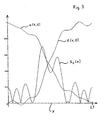
- the main difference to linear interpolation is that the subfunctions u (x, 0) and v (0, y) are no longer dependent only on the local position of the intermediate value to be determined, but rather that they e.g. B.
- the density functions e (x, 0), f (0, y) can be discrete functions or also continuous interpolation polynomials determined, for example, on the basis of the neutral density values k d '.
- the mathematical nomenclature or spelling that is usual for continuous functions is used below.
- the next step is to determine two functions s x (x) and s y (y), which describe the amount of the derivatives of the two density functions e (x, 0) and f (0, y). So it is:
- the three weights with which the color coordinates belonging to the circles FD2, FD3, FD4 are included in the interpolation are also calculated in an analogous manner.
- the color coordinates k 1 , k 2 can thus be determined for all template areas (indicated by the circles DD in FIG. 2) which lie within the interpolation quadrilateral FD1, FD2, FD3, FD4 or on its sides. These interpolations are carried out in an analogous manner in other interpolation quadrilaterals, so that for each template area (symbolically indicated by the circles DD) of the entire template V, the associated color coordinates k 1 and k 2 are determined by means of interpolation. The entirety of this color information then in turn forms the refined color data record, which has the same local resolution as the density data record.
- the position coordinate x is plotted on the abscissa of the diagram in FIG. 3 and the values of the partial function u (x, 0) of the weight function normalized to one are plotted on the ordinate.
- all three functions are shown as continuous functions.
- the local grid of the density data is shifted from the local grid of the color data, so that possibly no template areas (circles DD, Fig. 2) z. B lie on the connecting line of circles FD1 and FD2.
- the neutral density values k d 'of those template areas which are closest to this connecting line are used to determine the density functions.
- weight function w (x, y) it is also possible to choose a different form for the weight function w (x, y) than the product of the two subfunctions u (x, 0) and v (0, y), in order to z. B. to use even more information from the locally high-resolution density data set.
- a possible weight function which takes the information regarding the image content even more into account, is e.g. B .: where the function e is a two-dimensional discrete or continuous density function that describes the course of the density data in the interpolation quadrilateral, and ⁇ or ⁇ are again integration variables.
- the digital representation for the template has been created using the refined color data set and the density data set, and thus the complete image information regarding the content and color of the template V is available in digital form, the digital representation must still be brought into a data format, which can be processed by the output device 9 used (FIG. 1). If the output device 9 can process blue-green-red data, for example, then the k d ', k 1 , k 2 values contained in the digital representation are converted by a color space transformation using a matrix, which is inverse to that in the relationship ( I) is used, transformed. If the output device 9 requires the digital representations in a different data format, it is generally not a problem to convert the digital representations into this required data format using a corresponding transformation method.
- the digital representations or the overall digital image can be created using the well-known image processing program "Photo-Shop” from Adobe (Mountain View California, USA).
- the density data of the density data records are used to increase the sharpness impression of the Index prints 10 of digital filtering, e.g. B. a slight high-pass filtering, subjected.
- the saturation is adjusted, e.g. B. by shrinking or stretching the Color planes of the transformed and standardized color space.
- the individual, possibly reshaped, digital representations belonging to the selectable Number of templates include, of which positive supervisory images on the index print 10 should be included, electronically in a conventional manner to a digital Composed overall picture.
- this digital overall picture can also do other things Contain information that is usually provided on index prints 10, such as.
- From An index print 10 is then made on the overall digital image by means of the output device 9 an output medium 11 generated.
- output devices 9 are, for example Cathode ray tubes (CRT imagesetters), color monitors, thermal (sublimation) printers, Suitable for laser printers or inkjet printers.
- the output medium 11 can e.g. B. Photo paper, another form of paper, sheet material, or a color monitor.
- the digital representations or the overall digital picture on a disk e.g. B. to save a floppy disk or a photo CD, and from there make the index print 10 visible on a color monitor if necessary.
Landscapes
- Physics & Mathematics (AREA)
- General Physics & Mathematics (AREA)
- Facsimile Image Signal Circuits (AREA)
- Color Image Communication Systems (AREA)
- Projection-Type Copiers In General (AREA)
- Control Of Exposure In Printing And Copying (AREA)
Claims (12)
- Procédé de réalisation d'un photo-index avec un nombre pouvant être sélectionné d'images positives d'originaux photographiques correspondants, dans lequel :caractérisé en ce quechacun des originaux photographiques (V) est analysé de manière photo-électrique dans un poste de mesure (1) d'un copieur photographique au moyen d'un système d'analyse (2) réagissant à la couleur dans un grand nombre de premières zones d'analyse, afin de déterminer, à l'aide de données d'analyse ainsi obtenues, des valeurs d'insolation pour la réalisation de copies photographiques des originaux (V) ;au moyen des données d'analyse du système d'analyse (2) réagissant à la couleur on détermine pour chaque original (V) un jeu de données de couleur numériques qui contient des données de couleur représentatives de chaque première zone d'analyse individuelle ;à l'aide du jeu de données de couleur numériques, on réalise pour chaque original (V) une représentation numérique du contenu de l'image de l'original (V) ;les différentes représentations numériques des différents originaux photographiques (V), qui font partie du nombre pouvant être sélectionné d'images, sont regroupées en une image d'ensemble numérique dont on peut produire, au moyen d'un appareil de sortie (9), un photo-index (10) sur un support de sortie (11),;a) on utilise un système d'analyse (2) réagissant à la couleur présentant une résolution locale basse à moyenne ;b) les originaux photographiques (V) sont analysés de manière photo-électrique dans le poste de mesure au moyen d'un analyseur de densité (3) présentant une résolution locale élevée dans un grand nombre de deuxièmes zones d'analyse ;c) à partir des données d'analyse ainsi obtenues de l'analyseur de densité (3), on détermine pour chaque original (V) un jeu de données numériques de densité qui contient des données de densité représentatives de l'original (V) et qui présente une plus grande résolution locale que le jeu de données de couleur ;d) pour réaliser la représentation numérique du contenu d'image de l'original photographique (V) respectif, on utilise aussi bien le jeu de données de couleur correspondant que le jeu de données de densité correspondant.
- Procédé selon la revendication 1, caractérisé en ce que pour la détermination du jeu de données de densité, on réunit dans chaque cas les données d'analyse obtenues au moyen de l'analyseur de densité (3) provenant de plusieurs deuxièmes zones d'analyse, ce qui fait que la résolution locale du jeu de données de densité est d'une part inférieure à la résolution locale de l'analyseur de densité (3) et d'autre part supérieure à la résolution locale du jeu de données de couleur.
- Procédé selon l'une des revendications précédentes, caractérisé en ce que pour chaque original photographique (V) on détermine à partir du jeu de données de couleur correspondant, par détermination de valeurs intermédiaires, un jeu de données de couleur affiné pour cet original (V), lequel présente sensiblement la même résolution locale que le jeu de données de densité, et en ce que pour réaliser la représentation numérique du contenu d'image de l'original photographique (V) respectif, on utilise aussi bien le jeu de données de couleur affiné correspondant que le jeu de données de densité correspondant.
- Procédé selon la revendication 3, caractérisé en ce que les valeurs intermédiaires pour la réalisation du jeu de données de couleur affiné sont déterminées dans chaque cas au moyen d'une interpolation pour laquelle les données de couleur de la valeur intermédiaire à déterminer sont déterminées à partir de la moyenne pondérée des données de couleur des premières zones d'analyse directement voisines dans l'espace.
- Procédé selon la revendication 4, caractérisé en ce que le poids avec lequel les données de couleur des différentes premières zones d'analyse voisines entrent dans l'interpolation, est déterminé dans chaque cas au moyen d'une fonction pondérale qui dépend de deux coordonnées locales qui décrivent la position locale relative de la première zone d'analyse respective par rapport à la position locale de la valeur intermédiaire à déterminer.
- Procédé selon la revendication 5, caractérisé en ce que la fonction pondérale est le produit de deux fonctions partielles, la première fonction partielle ne dépendant que de la première coordonnée locale et la deuxième fonction partielle que de la deuxième coordonnée locale.
- Procédé selon l'une des revendications 4 à 6, caractérisé en ce que pour la détermination des poids, par lesquels les données de couleur respectives entrent dans l'interpolation pour la réalisation du jeu de données de couleur affiné, les données de densité du jeu de données de densité correspondant sont prises en compte.
- Procédé selon la revendication 7, caractérisé en ce qu'à l'aide des données de densité du jeu de données de densité, qui font partie des deuxièmes zones d'analyse, lesquelles se situent en ce qui concerne leur position locale entre les premières zones d'analyse entrant dans l'interpolation respective, on détermine les variations des données de densité dans un premier sens comme dans un deuxième sens, et ces variations, en particulier leurs valeurs absolues ou carrées, sont prises en compte dans la détermination des poids avec lesquels les données de couleur respectives entrent dans l'interpolation pour la réalisation du jeu de données de couleur affiné.
- Procédé selon la revendication 6, caractérisé en ce que la première fonction partielle dépend de manière linéaire de la première coordonnée locale, et en ce que la deuxième fonction partielle dépend de manière linéaire de la deuxième coordonnée locale.
- Procédé selon l'une des revendications précédentes, caractérisé en ce que les données d'analyse du système d'analyse (2) réagissant à la couleur sont soumises à des corrections de couleur et/ou de densité, et les données d'analyse corrigées sont utilisées pour déterminer les jeux de données de couleur numériques.
- Procédé selon l'une des revendications précédentes, caractérisé en ce que la gradation des différentes représentations numériques ou de l'image totale numérique est adaptée à la gradation du support de sortie (11).
- Procédé selon l'une des revendications précédentes, caractérisé en ce que les données de densité des jeux de données de densité sont soumises à un filtrage numérique pour accroítre l'impression de netteté du photo-index (10).
Priority Applications (5)
| Application Number | Priority Date | Filing Date | Title |
|---|---|---|---|
| EP96810569A EP0827015B1 (fr) | 1996-08-29 | 1996-08-29 | Procédé pour la fabrication d'images composées |
| DE59610861T DE59610861D1 (de) | 1996-08-29 | 1996-08-29 | Verfahren zur Erzeugung von Indexprints |
| US08/907,955 US6088136A (en) | 1996-08-29 | 1997-08-11 | Method for producing index prints |
| CA002214052A CA2214052A1 (fr) | 1996-08-29 | 1997-08-27 | Methode pour l'impression d'un repertoire de photographies |
| JP9231924A JPH10153828A (ja) | 1996-08-29 | 1997-08-28 | インデックスプリントの製作方法 |
Applications Claiming Priority (1)
| Application Number | Priority Date | Filing Date | Title |
|---|---|---|---|
| EP96810569A EP0827015B1 (fr) | 1996-08-29 | 1996-08-29 | Procédé pour la fabrication d'images composées |
Publications (2)
| Publication Number | Publication Date |
|---|---|
| EP0827015A1 EP0827015A1 (fr) | 1998-03-04 |
| EP0827015B1 true EP0827015B1 (fr) | 2003-12-10 |
Family
ID=8225686
Family Applications (1)
| Application Number | Title | Priority Date | Filing Date |
|---|---|---|---|
| EP96810569A Expired - Lifetime EP0827015B1 (fr) | 1996-08-29 | 1996-08-29 | Procédé pour la fabrication d'images composées |
Country Status (5)
| Country | Link |
|---|---|
| US (1) | US6088136A (fr) |
| EP (1) | EP0827015B1 (fr) |
| JP (1) | JPH10153828A (fr) |
| CA (1) | CA2214052A1 (fr) |
| DE (1) | DE59610861D1 (fr) |
Families Citing this family (2)
| Publication number | Priority date | Publication date | Assignee | Title |
|---|---|---|---|---|
| FR2777375B1 (fr) * | 1998-04-10 | 2001-04-13 | Eastman Kodak Co | Procede de selection automatique de la taille d'un support d'edition d'images numeriques, notamment d'images radiologiques |
| US20020114627A1 (en) * | 1998-10-21 | 2002-08-22 | Truc James A. | CD index print label |
Family Cites Families (12)
| Publication number | Priority date | Publication date | Assignee | Title |
|---|---|---|---|---|
| JPH0834530B2 (ja) * | 1986-07-04 | 1996-03-29 | キヤノン株式会社 | 画像読取装置の光学系調整用チヤ−ト |
| JPS63132571A (ja) * | 1986-11-25 | 1988-06-04 | Toshiba Corp | 画像読取り処理装置 |
| JP2634410B2 (ja) * | 1987-07-03 | 1997-07-23 | 富士写真フイルム株式会社 | 帯状プリント写真 |
| EP0308967B1 (fr) * | 1987-09-24 | 1994-08-03 | Fuji Photo Film Co., Ltd. | Méthode et dispositif pour tirages photographiques |
| DE58905761D1 (de) * | 1988-09-23 | 1993-11-04 | Gretag Imaging Ag | Belichtungssteuerungsverfahren und fotografisches farbkopiergeraet. |
| GB9008452D0 (en) * | 1990-04-12 | 1990-06-13 | Kodak Ltd | Scanner |
| EP0475897B1 (fr) * | 1990-09-10 | 1994-08-03 | Gretag Imaging Ag | Méthode pour la production de copies photographiques en couleur |
| US5184227A (en) * | 1991-11-21 | 1993-02-02 | Eastman Kodak Company | Photographic printer with index print generation |
| EP0586773B1 (fr) * | 1992-09-11 | 1998-05-20 | Gretag Imaging Ag | Méthode de production de copies à partir d'originaux photographiques |
| US5400152A (en) * | 1993-06-18 | 1995-03-21 | Eastman Kodak Company | High speed index printer |
| US5568269A (en) * | 1993-09-02 | 1996-10-22 | Eastman Kodak Company | Method and apparatus for scanning and printing documents with text and images |
| EP0697628A1 (fr) * | 1994-08-16 | 1996-02-21 | Gretag Imaging Ag | Procédé et dispositif pour créer des images composées avec une imprimante photographique |
-
1996
- 1996-08-29 DE DE59610861T patent/DE59610861D1/de not_active Expired - Lifetime
- 1996-08-29 EP EP96810569A patent/EP0827015B1/fr not_active Expired - Lifetime
-
1997
- 1997-08-11 US US08/907,955 patent/US6088136A/en not_active Expired - Lifetime
- 1997-08-27 CA CA002214052A patent/CA2214052A1/fr not_active Abandoned
- 1997-08-28 JP JP9231924A patent/JPH10153828A/ja active Pending
Also Published As
| Publication number | Publication date |
|---|---|
| CA2214052A1 (fr) | 1998-02-28 |
| US6088136A (en) | 2000-07-11 |
| DE59610861D1 (de) | 2004-01-22 |
| JPH10153828A (ja) | 1998-06-09 |
| EP0827015A1 (fr) | 1998-03-04 |
Similar Documents
| Publication | Publication Date | Title |
|---|---|---|
| DE69937707T2 (de) | Digitales Fotofinishingsystem mit digitaler Bildverarbeitung | |
| DE69021047T2 (de) | Verfahren zur ausdehnung des linearbereichs der aufgenommenen bilder eines films. | |
| DE69432239T2 (de) | Bildfelddetektion | |
| DE69120521T2 (de) | Verfahren und vorrichtung zum aufzeichen digitaler bilder | |
| DE69733882T2 (de) | Kamera mit einem einzigen bildaufnehmer | |
| DE19855885A1 (de) | Bildverarbeitungsverfahren und -vorrichtung | |
| DE69221665T2 (de) | Verfahren zur Ermittlung einer Belichtung | |
| DE68929194T2 (de) | Gerät zur Farbfilmanalyse | |
| EP0312499B1 (fr) | Copieur photographique en couleurs et procédé de contrôle de l'illumination | |
| DE3878704T2 (de) | Tonumsetzungsverfahren fuer bilder. | |
| DE68903992T2 (de) | Verfahren zur aenderung der schattierung von bildern. | |
| DE68921119T2 (de) | Tonumwandlungsverfahren für Bilder. | |
| DE19910645A1 (de) | Bildverarbeitungsverfahren | |
| DE19912511A1 (de) | Verfahren zur Erzeugung von Überfüllungskonturen in einer Druckseite | |
| DE69937706T2 (de) | Digitales Fotofinishingsystem mit digitaler Bildverarbeitung | |
| DE3324736A1 (de) | Eingabe-/ausgabesystem fuer die bilddarstellung | |
| DE3878282T2 (de) | Fotomechanischer apparat unter verwendung von fotoelektrischer abtastung. | |
| DE69937708T2 (de) | Digitales Fotofinishingsystem mit digitaler Bildverarbeitung | |
| EP0360751B1 (fr) | Procédé de commande d'exposition en tireuse photographique en couleur | |
| DE3620525C2 (fr) | ||
| DE4416314A1 (de) | Verfahren und Vorrichtung zur Aufnahme einer Bildszene | |
| EP0586773A1 (fr) | Méthode de production de copies à partir d'originaux photographiques | |
| DE69937705T2 (de) | Digitales Fotofinishingsystem mit Digital-Bildverarbeitung alternativer Farb-Fotografischer Aufnahmematerialien | |
| DE602005005766T2 (de) | Verfahren und Vorrichtung zur Lichtbildverarbeitung | |
| DE3531126A1 (de) | Vorrichtung zum herstellen fotografischer abzuege |
Legal Events
| Date | Code | Title | Description |
|---|---|---|---|
| PUAI | Public reference made under article 153(3) epc to a published international application that has entered the european phase |
Free format text: ORIGINAL CODE: 0009012 |
|
| AK | Designated contracting states |
Kind code of ref document: A1 Designated state(s): CH DE FR GB IT LI |
|
| AX | Request for extension of the european patent |
Free format text: AL;LT;LV;SI |
|
| 17P | Request for examination filed |
Effective date: 19980813 |
|
| AKX | Designation fees paid |
Free format text: CH DE FR GB IT LI |
|
| RBV | Designated contracting states (corrected) |
Designated state(s): CH DE FR GB IT LI |
|
| RAP1 | Party data changed (applicant data changed or rights of an application transferred) |
Owner name: IMIP LLC |
|
| GRAH | Despatch of communication of intention to grant a patent |
Free format text: ORIGINAL CODE: EPIDOS IGRA |
|
| GRAH | Despatch of communication of intention to grant a patent |
Free format text: ORIGINAL CODE: EPIDOS IGRA |
|
| GRAA | (expected) grant |
Free format text: ORIGINAL CODE: 0009210 |
|
| AK | Designated contracting states |
Kind code of ref document: B1 Designated state(s): CH DE FR GB IT LI |
|
| REG | Reference to a national code |
Ref country code: GB Ref legal event code: FG4D Free format text: NOT ENGLISH |
|
| REG | Reference to a national code |
Ref country code: CH Ref legal event code: NV Representative=s name: RIEDERER HASLER & PARTNER PATENTANWAELTE AG Ref country code: CH Ref legal event code: EP |
|
| GBT | Gb: translation of ep patent filed (gb section 77(6)(a)/1977) |
Effective date: 20031210 |
|
| REF | Corresponds to: |
Ref document number: 59610861 Country of ref document: DE Date of ref document: 20040122 Kind code of ref document: P |
|
| ET | Fr: translation filed | ||
| PLBE | No opposition filed within time limit |
Free format text: ORIGINAL CODE: 0009261 |
|
| STAA | Information on the status of an ep patent application or granted ep patent |
Free format text: STATUS: NO OPPOSITION FILED WITHIN TIME LIMIT |
|
| 26N | No opposition filed |
Effective date: 20040913 |
|
| REG | Reference to a national code |
Ref country code: CH Ref legal event code: PUE Owner name: EASTMAN KODAK COMPANY Free format text: IMIP LLC#CORPORATION TRUST CENTER, 1209 ORANGE STREET#WILMINGTON, DELAWARE 19801 (US) -TRANSFER TO- EASTMAN KODAK COMPANY#343 STATE STREET#ROCHESTER, NY 14650-2201 (US) |
|
| REG | Reference to a national code |
Ref country code: CH Ref legal event code: NV Representative=s name: RIEDERER HASLER & PARTNER PATENTANWAELTE AG |
|
| REG | Reference to a national code |
Ref country code: GB Ref legal event code: 732E |
|
| REG | Reference to a national code |
Ref country code: FR Ref legal event code: TP |
|
| PGFP | Annual fee paid to national office [announced via postgrant information from national office to epo] |
Ref country code: CH Payment date: 20110729 Year of fee payment: 16 |
|
| PGFP | Annual fee paid to national office [announced via postgrant information from national office to epo] |
Ref country code: IT Payment date: 20110816 Year of fee payment: 16 |
|
| PGFP | Annual fee paid to national office [announced via postgrant information from national office to epo] |
Ref country code: GB Payment date: 20120726 Year of fee payment: 17 |
|
| PGFP | Annual fee paid to national office [announced via postgrant information from national office to epo] |
Ref country code: FR Payment date: 20120809 Year of fee payment: 17 Ref country code: DE Payment date: 20120831 Year of fee payment: 17 |
|
| REG | Reference to a national code |
Ref country code: CH Ref legal event code: PL |
|
| PG25 | Lapsed in a contracting state [announced via postgrant information from national office to epo] |
Ref country code: CH Free format text: LAPSE BECAUSE OF NON-PAYMENT OF DUE FEES Effective date: 20120831 Ref country code: LI Free format text: LAPSE BECAUSE OF NON-PAYMENT OF DUE FEES Effective date: 20120831 |
|
| PG25 | Lapsed in a contracting state [announced via postgrant information from national office to epo] |
Ref country code: IT Free format text: LAPSE BECAUSE OF NON-PAYMENT OF DUE FEES Effective date: 20120829 |
|
| GBPC | Gb: european patent ceased through non-payment of renewal fee |
Effective date: 20130829 |
|
| PG25 | Lapsed in a contracting state [announced via postgrant information from national office to epo] |
Ref country code: DE Free format text: LAPSE BECAUSE OF NON-PAYMENT OF DUE FEES Effective date: 20140301 |
|
| REG | Reference to a national code |
Ref country code: DE Ref legal event code: R119 Ref document number: 59610861 Country of ref document: DE Effective date: 20140301 |
|
| REG | Reference to a national code |
Ref country code: FR Ref legal event code: ST Effective date: 20140430 |
|
| PG25 | Lapsed in a contracting state [announced via postgrant information from national office to epo] |
Ref country code: GB Free format text: LAPSE BECAUSE OF NON-PAYMENT OF DUE FEES Effective date: 20130829 |
|
| PG25 | Lapsed in a contracting state [announced via postgrant information from national office to epo] |
Ref country code: FR Free format text: LAPSE BECAUSE OF NON-PAYMENT OF DUE FEES Effective date: 20130902 |