EP0827062B1 - Appareil électronique et son procédé de commande mode de fonctionnement - Google Patents
Appareil électronique et son procédé de commande mode de fonctionnement Download PDFInfo
- Publication number
- EP0827062B1 EP0827062B1 EP97114659A EP97114659A EP0827062B1 EP 0827062 B1 EP0827062 B1 EP 0827062B1 EP 97114659 A EP97114659 A EP 97114659A EP 97114659 A EP97114659 A EP 97114659A EP 0827062 B1 EP0827062 B1 EP 0827062B1
- Authority
- EP
- European Patent Office
- Prior art keywords
- layer controller
- electronic apparatus
- power supply
- link layer
- bus
- Prior art date
- Legal status (The legal status is an assumption and is not a legal conclusion. Google has not performed a legal analysis and makes no representation as to the accuracy of the status listed.)
- Expired - Lifetime
Links
Images


Classifications
-
- H—ELECTRICITY
- H04—ELECTRIC COMMUNICATION TECHNIQUE
- H04L—TRANSMISSION OF DIGITAL INFORMATION, e.g. TELEGRAPHIC COMMUNICATION
- H04L12/00—Data switching networks
- H04L12/28—Data switching networks characterised by path configuration, e.g. LAN [Local Area Networks] or WAN [Wide Area Networks]
- H04L12/40—Bus networks
- H04L12/40052—High-speed IEEE 1394 serial bus
- H04L12/40078—Bus configuration
-
- H—ELECTRICITY
- H04—ELECTRIC COMMUNICATION TECHNIQUE
- H04L—TRANSMISSION OF DIGITAL INFORMATION, e.g. TELEGRAPHIC COMMUNICATION
- H04L12/00—Data switching networks
- H04L12/28—Data switching networks characterised by path configuration, e.g. LAN [Local Area Networks] or WAN [Wide Area Networks]
- H04L12/40—Bus networks
- H04L12/40006—Architecture of a communication node
- H04L12/40045—Details regarding the feeding of energy to the node from the bus
-
- G—PHYSICS
- G06—COMPUTING OR CALCULATING; COUNTING
- G06F—ELECTRIC DIGITAL DATA PROCESSING
- G06F1/00—Details not covered by groups G06F3/00 - G06F13/00 and G06F21/00
- G06F1/26—Power supply means, e.g. regulation thereof
- G06F1/32—Means for saving power
-
- G—PHYSICS
- G06—COMPUTING OR CALCULATING; COUNTING
- G06F—ELECTRIC DIGITAL DATA PROCESSING
- G06F1/00—Details not covered by groups G06F3/00 - G06F13/00 and G06F21/00
- G06F1/26—Power supply means, e.g. regulation thereof
- G06F1/32—Means for saving power
- G06F1/3203—Power management, i.e. event-based initiation of a power-saving mode
- G06F1/3234—Power saving characterised by the action undertaken
- G06F1/325—Power saving in peripheral device
- G06F1/3253—Power saving in bus
-
- H—ELECTRICITY
- H04—ELECTRIC COMMUNICATION TECHNIQUE
- H04L—TRANSMISSION OF DIGITAL INFORMATION, e.g. TELEGRAPHIC COMMUNICATION
- H04L12/00—Data switching networks
- H04L12/28—Data switching networks characterised by path configuration, e.g. LAN [Local Area Networks] or WAN [Wide Area Networks]
- H04L12/40—Bus networks
- H04L12/40052—High-speed IEEE 1394 serial bus
-
- Y—GENERAL TAGGING OF NEW TECHNOLOGICAL DEVELOPMENTS; GENERAL TAGGING OF CROSS-SECTIONAL TECHNOLOGIES SPANNING OVER SEVERAL SECTIONS OF THE IPC; TECHNICAL SUBJECTS COVERED BY FORMER USPC CROSS-REFERENCE ART COLLECTIONS [XRACs] AND DIGESTS
- Y02—TECHNOLOGIES OR APPLICATIONS FOR MITIGATION OR ADAPTATION AGAINST CLIMATE CHANGE
- Y02D—CLIMATE CHANGE MITIGATION TECHNOLOGIES IN INFORMATION AND COMMUNICATION TECHNOLOGIES [ICT], I.E. INFORMATION AND COMMUNICATION TECHNOLOGIES AIMING AT THE REDUCTION OF THEIR OWN ENERGY USE
- Y02D10/00—Energy efficient computing, e.g. low power processors, power management or thermal management
Definitions
- This invention relates to an electronic apparatus connected to and used with, for example, serial bus using an IEEE 1394 High performance serial bus format, and more particularly to an electronic apparatus wherein the power dissipation of a communication interface is reduced.
- a system is available wherein electronic apparatus such as a personal computer, a digital video cassette recorder and a digital television receiver are interconnected by an IEEE 1394 serial bus such that packets of a digital video signal, a digital audio signal and a control signal are communicated between the electronic apparatus.
- electronic apparatus such as a personal computer, a digital video cassette recorder and a digital television receiver are interconnected by an IEEE 1394 serial bus such that packets of a digital video signal, a digital audio signal and a control signal are communicated between the electronic apparatus.
- FIG. 5 shows an example of a system of the type just described.
- electronic apparatus A to C may be a personal computer, a digital video cassette recorder and some other electronic apparatus.
- Ports P of the electronic apparatus A and B and ports P of the electronic apparatus B and C are interconnected by IEEE 1394 serial bus cables 11 and 12, respectively.
- Such electronic apparatus are hereinafter referred to suitably as nodes.
- each of the IEEE 1394 serial cables 11 and 12 has two pairs of twisted pair cables provided in the inside thereof. One pair of the two pairs of twisted pair cables is used for transmission of data, and the other pair is used for transmission of a strobe signal. Each node outputs a bias voltage to one of the two pairs of twisted pair cables and detects a bias voltage on the other pair of twisted pair cables.
- each node includes, as an interface (which may be hereinafter referred to suitably as 1394 interface) for performing communication via an IEEE 1394 serial bus, a physical layer controller (PHY) 13, a link layer controller (LINK) 14 and a CPU 15.
- the physical layer controller 13 is formed from an IC and has functions of initialization of a bus, encoding/decoding of transmission/reception data, bus arbitration, outputting/detection of a bias voltage and so forth.
- the link layer controller 14 is formed from an IC and has link layer controlling functions such as production/detection of an error correction code, production/detection of a packet and so forth.
- the CPU 15 is formed from a microcomputer and has a controlling function for an application and so forth.
- bus resetting takes place, and allocation of physical addresses to the individual nodes is automatically completed in a predetermined time. Then, after the allocation of physical addresses to the individual nodes is completed, the nodes A to C start transactions necessary upon bus resetting determined by a protocol.
- a system for periodically transmitting signal to/from sleeping node identifying its existence to a network and awakening the sleeping node responding to received instruction is known from EP-A-604871.
- a network controller being configured for allowing a sleep mode for a data processing node connected to a network controller, a transceiver being configured to monitor for transmissions on a data processing network when the data processing node is in the sleep node and the data processing node being configured to awake from the sleep mode in response to the transceiver receiving a transmission including an instruction field including a node address for the data processing node and an awaking instruction.
- the link layer controller thereof when the electronic apparatus is not connected to a second one of the electronic apparatus via the bus, the link layer controller thereof does not operate, and after the connection is established, the link layer controller operates. Consequently, when the electronic apparatus is not connected to any other electronic apparatus, the link layer controller thereof does not dissipate power, and accordingly, saving of the power dissipation can be achieved.
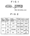
- FIG. 1 shows a system to which the present invention is applied.
- the system shown is composed of two nodes of a digital video cassette recorder integrated with a camera (DCAM) and a digital video cassette recorder (DVCR).
- the digital video cassette recorder integrated with a camera and the digital video cassette recorder are interconnected by a cable of an IEEE 1394 serial bus.
- FIG. 2 illustrates modes of a 1394 interface of each of the nodes.
- set power supply represents a power supply to the entire node.
- off of the set power supply represents that no power supply voltage is supplied from the outside to the apparatus, that is, either the apparatus is not connected to a plug or the apparatus has no battery loaded therein, or a power supply switch of the apparatus is set to an off state while a power supply voltage is supplied from the outside to the apparatus.
- “on” of the set power supply represents that a power supply voltage is supplied from the outside and a power supply switch of the apparatus is set to an on state.
- the "on” signifies that the digital video cassette recorder integrated with a camera is set to a video mode or a camera mode.
- the mode of the 1394 interface is "off" irrespective of whether or not there is a bus connection.
- the power supply mode of each of the blocks of the CPU, link layer controller and physical layer controller which form the 1394 interface is "reset".
- the power supply mode is "reset" the block does not operate.
- FIG. 3 is a diagram illustrating a flow of signals communicated between the digital video cassette recorder integrated with a camera shown in FIG. 1 and another node (here, the digital video cassette recorder) via the IEEE 1394 serial bus and corresponding general operation of the 1354 interface in the digital video cassette recorder integrated with a camera.
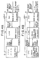
- FIG. 4A illustrates operation of the 1394 interface in the front half of FIG. 3
- FIG. 4B illustrates operation of the 1394 interface in the rear half of FIG. 3.
- operation of the 1394 interface in the present embodiment is described with reference to FIGS. 1, 3, 4A and 4B.
- the set power supplies to the digital video cassette recorder integrated with a camera and the digital video cassette recorder are switched from off to on.
- the digital video cassette recorder integrated with a camera and the digital video cassette recorder are connected to each other by a cable of an IEEE 1394 serial bus as shown in FIG. 1.
- the physical layer controller 13 After the power supply mode of the physical layer controller 13 changes to "on", the physical layer controller 13 outputs a bias voltage (TP bias) to an associated IEEE 1394 serial bus. Similarly, also the digital video cassette recorder which is the other node outputs a bias voltage (TP bias) to the IEEE 1394 serial bus.
- TP bias bias voltage
- the physical layer controller 13 of the digital video cassette recorder integrated with a camera detects a bias voltage outputted from the digital video cassette recorder to the IEEE 1394 serial bus, it transmits the bias voltage to the CPU 15.
- the CPU 15 thus knows that the digital video cassette recorder integrated with a camera has been connected to the other node by the IEEE 1394 serial bus. Further, when the serial voltage is detected, the physical layer controller 13 starts bus resetting.
- connection relationship (tree structure) of the nodes is determined automatically. It is assumed here that it is decided that the digital video cassette recorder integrated with a camera becomes a parent and the digital video cassette recorder becomes a child.
- a self ID packet is successively transmitted to the IEEE 1394 serial bus from the nodes in order beginning with the child node of the tree structure. Then, ascending physical ID numbers are allocated to the nodes in order of transmission of the self ID packets.
- the physical address #0 is allocated to the digital video cassette recorder which first transmits its self ID packet
- the physical address #1 is allocated to the digital video cassette recorder integrated with a camera which transmits its self ID packet later.
- the physical layer controller 13 of each node can know the total number of nodes connected to the IEEE 1394 serial bus from the number of self ID packets received from the IEEE 1394 serial bus.
- the physical layer controller 13 of each node since the physical layer controller 13 of each node receives a self ID packet only from the other node connected directly to the node, it can be discriminated that the total number of nodes is 2.
- a self ID packet has information (L bit) indicative of a status of the link layer controller 14, and information (C bit) indicative of whether or not the node itself is capable of acting as an isochronous resource manager (IRM) which is a managing node of the bus.
- connection relationship (tree structure) of the nodes is automatically decided as described hereinabove.
- the CPU 15 instructs the physical layer controller 13 to set the root hold bit (RHB) to "1".
- RHB 1
- a self ID packet is successively transmitted to any other node from the nodes in order beginning with the child node.
- the physical address #0 is allocated to the digital video cassette recorder integrated with a camera which transmits its self ID packet first
- the physical address #1 is allocated to the digital video cassette recorder integrated with a camera which transmits its self ID packet later.
- the physical layer controller 13 of each node transmits received self ID packets to the link layer controller 14.
- the link layer controller 14 can discriminate, from the number of the received self ID packets, the total number of nodes connected to the IEEE 1394 serial bus.
- the digital video cassette recorder integrated with a camera can discriminate, from the facts that the total number of nodes is 2 and the physical address of the digital video cassette recorder integrated with a camera itself is #1, that the digital video cassette recorder integrated with a camera itself has a maximum physical address from among the nodes connected to the IEEE 1394 serial bus.
- the link layer controller 14 in the digital video cassette recorder integrated with a camera can discriminate that the total node number is 2 and the physical address of the isochronous resource manager is #1 (that is, the digital video cassette recorder integrated with a camera itself).
- the CPU 15 inquires of the link layer controller 14 about the isochronous resource manager and the total node number, then it can receive a reply from the link layer controller 14 and discriminate that the isochronous resource manager is the digital video cassette recorder integrated with a camera itself. This manner is illustrated in FIG. 4B. Consequently, the digital video cassette recorder integrated with a camera can acquire a band and a channel by itself, registers them into an internal register and sends out isochronous data immediately.
- the present invention can be applied similarly also to other systems which include three or more different nodes such as a personal computer.
Landscapes
- Engineering & Computer Science (AREA)
- Theoretical Computer Science (AREA)
- Physics & Mathematics (AREA)
- Signal Processing (AREA)
- General Engineering & Computer Science (AREA)
- General Physics & Mathematics (AREA)
- Computer Networks & Wireless Communication (AREA)
- Small-Scale Networks (AREA)
- Power Sources (AREA)
- Information Transfer Systems (AREA)
- Electrophonic Musical Instruments (AREA)
- Electrotherapy Devices (AREA)
- Debugging And Monitoring (AREA)
Claims (14)
- Appareil électronique destiné à être utilisé avec un système, dans lequel ledit appareil électronique peut être relié à un second appareil électronique par un bus (11, 12) afin d'effectuer une communication avec ledit second appareil électronique comprenant :
une interface de communication destinée à effectuer une communication via ledit bus (11, 12), ladite interface de communication comprenant un contrôleur de couche physique (13), un contrôleur de couche de liaison (14), et une CPU (15) ;
caractérisé en ce que
ladite CPU (15) est adaptée afin de contrôler les modes d'alimentation dudit contrôleur de couche physique (13) et dudit contrôleur de couche de liaison (14), dans laquelle
le mode d'alimentation dudit contrôleur de couche physique (13) passe à un état d'alimentation si ledit appareil électronique est dans un état d'alimentation ;
le mode d'alimentation dudit contrôleur de couche physique (13) est maintenu, même si ledit appareil électronique est dans un état d'alimentation, dans un état de réinitialisation après que ladite CPU (15) ait demandé audit contrôleur de couche de liaison (14) de passer à un état d'alimentation, et
lorsque la connexion dudit appareil électronique audit second appareil électronique via ledit bus (11, 12) est détectée par un moyen de détection, ladite CPU (15) transmet les informations du mode d'alimentation dudit contrôleur de couche de liaison (14) indiquant l'état d'alimentation audit contrôleur de couche physique (13), afin de faire passer le mode d'alimentation dudit contrôleur de couche de liaison (14) à un état d'alimentation, et demande audit contrôleur de couche physique (13) de lancer une réinitialisation du bus, et
ledit contrôleur de couche physique (13) est adapté afin de gérer une information représentative du mode d'alimentation et une capacité de gestion de bus dudit contrôleur de couche de liaison (14) incluse dans un paquet à envoyer par ledit appareil électronique sur ledit bus (11, 12) après la réinitialisation du bus. - Appareil électronique selon la revendication 1, dans lequel
ledit contrôleur de couche physique (13) comprend ledit moyen de détection et un moyen adapté afin d'indiquer à ladite CPU la détection. - Appareil électronique selon la revendication 1 ou 2, dans lequel
ledit bus est un bus série conforme au format IEEE 1394. - Appareil électronique selon l'une quelconque des revendications 1 à 3, dans lequel
ledit appareil électronique peut être entraîné par une batterie. - Appareil électronique selon l'une quelconque des revendications 1 à 4, dans lequel
ledit appareil électronique est adapté afin de conserver l'état de réinitialisation du mode d'alimentation dudit contrôleur de couche de liaison (14) en tant qu'informations représentatives d'un statut d'alimentation. - Appareil électronique selon la revendication 5, dans lequel,
lorsque ladite CPU (15) reçoit la notification de la part dudit contrôleur de couche physique (13), ladite CPU (15) est adaptée afin d'effectuer une recherche auprès dudit contrôleur de couche de liaison (14), et, si les informations représentatives du statut d'alimentation dudit contrôleur de couche de liaison (14) sont un mode de réinitialisation, ladite CPU (15) est alors adaptée afin d'annuler l'état de réinitialisation des informations représentatives du statut d'alimentation dudit contrôleur de couche de liaison (14) afin de permettre le fonctionnement dudit contrôleur de couche de liaison (14). - Appareil électronique selon la revendication 6, dans lequel
ledit appareil électronique est adapté afin d'inclure, dans l'ID d'un paquet à envoyer par ledit appareil électronique, les informations représentatives du statut d'alimentation, dans lequel les informations représentatives du statut d'alimentation sont un bit représentatif d'un statut dudit contrôleur de couche de liaison. - Procédé de contrôle de mode de fonctionnement destiné à un appareil électronique, comprenant l'étape consistant à :contrôler un contrôleur de couche de liaison (14) dans ledit appareil électronique de telle sorte que ledit contrôleur de couche de liaison (14) ne fonctionne pas lorsque ledit appareil électronique n'est pas relié à un second appareil électronique via un bus (10, 11),caractérisé en ce quele mode d'alimentation d'un contrôleur de couche physique (13) passe à un état d'alimentation si ledit appareil électronique est dans un état d'alimentation;le mode d'alimentation dudit contrôleur de couche physique (13) est maintenu, même si ledit appareil électronique est dans un état d'alimentation, dans un état de réinitialisation après que ledit contrôleur de couche de liaison (14) ait reçu l'ordre de passer à un état d'alimentation, etlorsque la connexion dudit appareil électronique audit second appareil électronique via ledit bus (11, 12) est détectée, les informations du mode d'alimentation dudit contrôleur de couche de liaison (14) indiquant l'état d'alimentation sont transmises audit contrôleur de couche physique (13), le mode d'alimentation dudit contrôleur de couche de liaison (14) passe à un état d'alimentation, et ledit contrôleur de couche physique (13) reçoit l'ordre de lancer la réinitialisation du bus,dans lequelledit contrôleur de couche physique (13) gère une information représentative du mode d'alimentation et une capacité de gestion de bus dudit contrôleur de couche de liaison (14) incluse dans un paquet à envoyer par ledit appareil électronique sur ledit bus (11, 12) après la réinitialisation du bus.
- Procédé de contrôle de mode de fonctionnement selon la revendication 8, dans lequel
la communication est effectuée par une interface de communication, ladite interface de communication comprenant ledit contrôleur de couche physique (13), ledit contrôleur de couche de liaison (14), et un élément de fonction de contrôle (15) destiné à une couche d'application. - Procédé de contrôle de mode de fonctionnement selon la revendication 9, dans lequel,
lorsqu'une alimentation dudit appareil électronique passe d'un état de coupure à un état d'alimentation, un mode d'alimentation dudit élément de fonction de contrôle destiné à la couche d'application est activé et un état de réinitialisation d'un mode d'alimentation dudit contrôleur de couche physique (13) est annulé, et l'alimentation dudit contrôleur de couche de liaison (14) n'est pas activée tant qu'il n'a pas été détecté que ledit appareil électronique est relié audit second appareil électronique via ledit bus (10, 11). - Procédé de contrôle de mode de fonctionnement selon la revendication 10, dans lequel,
une fois que le mode d'alimentation dudit élément de fonction de contrôle (15) destiné à la couche d'application a été activé et que l'état de réinitialisation du mode d'alimentation dudit contrôleur de couche physique (13) a été annulé, ledit contrôleur de couche physique (13) transmet une tension de polarisation audit bus (10, 11) et détecte une tension de polarisation dudit second appareil électronique. - Procédé de contrôle de mode de fonctionnement selon la revendication 11, dans lequel,
lorsque la tension de polarisation est détectée, la réinitialisation dudit bus (10, 11) est lancée, après quoi une relation de connexion entre ledit premier et ledit second appareils électroniques reliés l'un à l'autre est décidée. - Procédé de contrôle de mode de fonctionnement selon la revendication 12, dans lequel,
une fois que la relation de connexion a été décidée, ledit élément de fonction de contrôle (15) destiné à la couche d'application effectue une recherche auprès dudit contrôleur de couche de liaison (14) et, si le statut d'alimentation dudit contrôleur de couche de liaison (14) est un mode de réinitialisation, ledit élément de fonction de contrôle (15) annule l'état de réinitialisation du mode d'alimentation dudit contrôleur de couche de liaison (14). - Procédé de contrôle de mode de fonctionnement selon la revendication 13, dans lequel
la réinitialisation dudit bus (10, 11) par ledit contrôleur de couche physique (13) est lancée à nouveau après l'annulation de l'état de réinitialisation du mode d'alimentation dudit contrôleur de couche de liaison (14).
Applications Claiming Priority (2)
| Application Number | Priority Date | Filing Date | Title |
|---|---|---|---|
| JP24260796A JP3601205B2 (ja) | 1996-08-26 | 1996-08-26 | 電子機器及びその動作モード制御方法 |
| JP242607/96 | 1996-08-26 |
Publications (2)
| Publication Number | Publication Date |
|---|---|
| EP0827062A1 EP0827062A1 (fr) | 1998-03-04 |
| EP0827062B1 true EP0827062B1 (fr) | 2007-05-23 |
Family
ID=17091574
Family Applications (1)
| Application Number | Title | Priority Date | Filing Date |
|---|---|---|---|
| EP97114659A Expired - Lifetime EP0827062B1 (fr) | 1996-08-26 | 1997-08-25 | Appareil électronique et son procédé de commande mode de fonctionnement |
Country Status (7)
| Country | Link |
|---|---|
| US (1) | US5919261A (fr) |
| EP (1) | EP0827062B1 (fr) |
| JP (1) | JP3601205B2 (fr) |
| KR (1) | KR100514262B1 (fr) |
| CN (1) | CN100481800C (fr) |
| AT (1) | ATE363094T1 (fr) |
| DE (1) | DE69737743T2 (fr) |
Families Citing this family (37)
| Publication number | Priority date | Publication date | Assignee | Title |
|---|---|---|---|---|
| JPH10303949A (ja) * | 1997-04-30 | 1998-11-13 | Hitachi Ltd | バス制御装置および情報処理システム |
| US6219697B1 (en) * | 1997-05-02 | 2001-04-17 | 3Com Corporation | Method and apparatus for operating the internet protocol over a high-speed serial bus |
| US6131129A (en) * | 1997-07-30 | 2000-10-10 | Sony Corporation Of Japan | Computer system within an AV/C based media changer subunit providing a standarized command set |
| US6275882B1 (en) * | 1997-09-30 | 2001-08-14 | Encanto Networks | Method and apparatus for providing a hot docking interface for transmitting digital video data |
| US6298406B1 (en) * | 1997-10-24 | 2001-10-02 | Sony Corporation | Method of and apparatus for detecting direction of reception of bus packets and controlling direction of transmission of bus packets within an IEEE 1394 serial bus node |
| US6157972A (en) * | 1997-12-05 | 2000-12-05 | Texas Instruments Incorporated | Apparatus and method for processing packetized information over a serial bus |
| EP0932103A1 (fr) * | 1998-01-27 | 1999-07-28 | Deutsche Thomson-Brandt Gmbh | Méthode et dispositif pour transférer des données bidirectionelles entre un bus IEEE 1394 et un appareil |
| KR100556471B1 (ko) * | 1998-03-20 | 2006-05-25 | 엘지전자 주식회사 | 마이컴의초기화방법 |
| KR100298979B1 (ko) * | 1998-06-12 | 2001-09-06 | 윤종용 | 아이 트리플 이 1394 시리얼 버스 토폴로지 최적화방법 |
| JP2000020175A (ja) * | 1998-06-26 | 2000-01-21 | Toshiba Corp | 電子機器 |
| WO2000003519A1 (fr) * | 1998-07-09 | 2000-01-20 | Sony Corporation | Procede de commande de communication, systeme de communication et dispositif electronique |
| JP4025429B2 (ja) * | 1998-08-21 | 2007-12-19 | 富士通株式会社 | 接続制御装置及び接続制御方法 |
| US6496862B1 (en) | 1998-08-25 | 2002-12-17 | Mitsubishi Electric Research Laboratories, Inc. | Remote monitoring and control of devices connected to an IEEE 1394 bus via a gateway device |
| US6505255B1 (en) | 1999-04-29 | 2003-01-07 | Mitsubishi Electric Information Technology Center America, Inc. (Ita) | Method for formatting and routing data between an external network and an internal network |
| US7013354B1 (en) * | 1998-10-05 | 2006-03-14 | Canon Kabushiki Kaisha | Channel protocol for IEEE 1394 data transmission |
| US6604201B1 (en) | 1998-10-28 | 2003-08-05 | Matsushita Electric Industrial Co., Ltd. | Network unit with power saving mode inhibit based on interconnection relationship to neighboring nodes which is stored on the unit |
| KR100587278B1 (ko) * | 1999-02-08 | 2006-06-08 | 엘지전자 주식회사 | 버스시스템에서의 노드 웨이크-업(Wake-up) 장치 및 방법 |
| EP1033855A1 (fr) * | 1999-03-03 | 2000-09-06 | Deutsche Thomson-Brandt Gmbh | Procédé et appareil pour transférer des données par bus vers et à partir d' un dispositif à contrôler par ce bus |
| US6523064B1 (en) | 1999-04-29 | 2003-02-18 | Mitsubishi Electric Research Laboratories, Inc | Network gateway for collecting geographic data information |
| US6633547B1 (en) | 1999-04-29 | 2003-10-14 | Mitsubishi Electric Research Laboratories, Inc. | Command and control transfer |
| US6378000B1 (en) | 1999-04-29 | 2002-04-23 | Mitsubish Electric Research Laboratories, Inc | Address mapping in home entertainment network |
| US7016595B1 (en) | 1999-05-28 | 2006-03-21 | Nikon Corporation | Television set capable of controlling external device and image storage controlled by television set |
| WO2001003377A1 (fr) * | 1999-07-06 | 2001-01-11 | Matsushita Electric Industrial Co., Ltd. | Procede de commande de dispositif et support d'enregistrement de programme sur lequel ce procede est enregistre |
| JP4449141B2 (ja) * | 2000-02-22 | 2010-04-14 | ソニー株式会社 | 電源制御装置、電源制御システム |
| US6704819B1 (en) * | 2000-04-19 | 2004-03-09 | Microsoft Corporation | Method and apparatus for device sharing and arbitration |
| JP3544932B2 (ja) | 2000-10-05 | 2004-07-21 | Necエレクトロニクス株式会社 | 電子装置及びその電力制御方法 |
| EP1211895A1 (fr) * | 2000-11-30 | 2002-06-05 | Deutsche Thomson-Brandt Gmbh | Arrangement de circuit pour le traitement d'une bande de canaux de télévision numérique |
| JP2002176466A (ja) * | 2000-12-08 | 2002-06-21 | Fuji Film Microdevices Co Ltd | 信号処理回路及び信号処理方法 |
| WO2003054673A1 (fr) * | 2001-12-21 | 2003-07-03 | Koninklijke Philips Electronics N.V. | Systeme de bus de communication pouvant fonctionner en mode veille ou en mode normal |
| US20030145143A1 (en) * | 2002-01-31 | 2003-07-31 | Adelman Lonnie W. | Communicable coupling systems for electronic appliances |
| JP3844218B2 (ja) * | 2002-04-03 | 2006-11-08 | ソニー株式会社 | 信号処理システム、信号入力装置及び通信制御方法 |
| JP4506221B2 (ja) * | 2004-03-18 | 2010-07-21 | 富士ゼロックス株式会社 | 複合機およびその制御方法 |
| KR100703795B1 (ko) * | 2005-09-06 | 2007-04-06 | 삼성전자주식회사 | 버스 리셋 발생시 식별 정보를 획득하는 장치 및 그 방법 |
| US9323311B2 (en) * | 2006-06-22 | 2016-04-26 | Broadcom Corporation | Method and system for packet based signaling between A Mac and A PHY to manage energy efficient network devices and/or protocols |
| US7681051B2 (en) * | 2006-08-30 | 2010-03-16 | Agere Systems Inc. | Transitioning of a port in a communications system from an active state to a standby state |
| EP2339430B1 (fr) * | 2009-12-28 | 2013-09-18 | Advanced Connection Technology, Inc. | Dispositif d'adaptation électrique et procédé de gestion d'alimentation électrique |
| US8259482B2 (en) * | 2009-12-28 | 2012-09-04 | Advanced Connection Technology, Inc. | Power adapter apparatus and power management method |
Family Cites Families (6)
| Publication number | Priority date | Publication date | Assignee | Title |
|---|---|---|---|---|
| US4652874A (en) * | 1984-12-24 | 1987-03-24 | Motorola, Inc. | Serial communication interface for a local network controller |
| US5007051A (en) * | 1987-09-30 | 1991-04-09 | Hewlett-Packard Company | Link layer protocol and apparatus for data communication |
| CA2091851A1 (fr) * | 1992-03-25 | 1993-09-26 | Michael J. Sherman | Reseau et methode de communication a couhes de liaison de donnees |
| US5404544A (en) * | 1992-06-05 | 1995-04-04 | Advanced Micro Devices | System for periodically transmitting signal to/from sleeping node identifying its existence to a network and awakening the sleeping node responding to received instruction |
| JPH07134628A (ja) * | 1993-11-10 | 1995-05-23 | Hitachi Ltd | 省電力制御方法および情報処理装置 |
| JP3617105B2 (ja) * | 1995-02-16 | 2005-02-02 | ソニー株式会社 | 電子機器及びその動作モード制御方法 |
-
1996
- 1996-08-26 JP JP24260796A patent/JP3601205B2/ja not_active Expired - Lifetime
-
1997
- 1997-08-13 US US08/910,854 patent/US5919261A/en not_active Expired - Lifetime
- 1997-08-25 AT AT97114659T patent/ATE363094T1/de active
- 1997-08-25 EP EP97114659A patent/EP0827062B1/fr not_active Expired - Lifetime
- 1997-08-25 DE DE69737743T patent/DE69737743T2/de not_active Expired - Lifetime
- 1997-08-26 CN CNB971178852A patent/CN100481800C/zh not_active Expired - Lifetime
- 1997-08-26 KR KR1019970040865A patent/KR100514262B1/ko not_active Expired - Lifetime
Also Published As
| Publication number | Publication date |
|---|---|
| US5919261A (en) | 1999-07-06 |
| ATE363094T1 (de) | 2007-06-15 |
| DE69737743T2 (de) | 2008-06-26 |
| CN1175833A (zh) | 1998-03-11 |
| CN100481800C (zh) | 2009-04-22 |
| DE69737743D1 (de) | 2007-07-05 |
| KR100514262B1 (ko) | 2005-11-25 |
| JP3601205B2 (ja) | 2004-12-15 |
| EP0827062A1 (fr) | 1998-03-04 |
| KR19980018996A (ko) | 1998-06-05 |
| JPH1070561A (ja) | 1998-03-10 |
Similar Documents
| Publication | Publication Date | Title |
|---|---|---|
| EP0827062B1 (fr) | Appareil électronique et son procédé de commande mode de fonctionnement | |
| EP0727729B1 (fr) | Interface de bus et procédé de commande d'économie d'énergie associé | |
| US6108718A (en) | Communication method and electronic apparatus thereof | |
| US6690648B2 (en) | Data communication apparatus, method, and system utilizing reception capability information of a destination node | |
| US6996112B2 (en) | Information communication system, information communication method, information signal processing device and information signal processing method, and storage medium | |
| EP0971508A2 (fr) | Procédé et appareil pour la transmission de données sur un bus de données | |
| JP2001306428A (ja) | ネットワーク機器、ネットワークシステム、通信方法及び記録媒体 | |
| EP0739112B1 (fr) | Dispositifs électroniques et contrôle de leur mode de fonctionnement | |
| US7203787B2 (en) | Information processing apparatus and method that utilizes stored information about a mountable device | |
| JP3773688B2 (ja) | ネットワークに接続可能な機器 | |
| JPH10290238A (ja) | 電子機器及びその情報伝送方法 | |
| EP1037431A1 (fr) | Procede de transfert de donnees et systeme de transfert de donnees | |
| JP2001275066A (ja) | 画像処理装置およびその方法、並びに、記憶媒体 | |
| US7739373B2 (en) | Detecting whether a connection between apparatuses includes a predetermined transmission medium | |
| JPH11215143A (ja) | データ通信装置及び方法 | |
| US20060017811A1 (en) | Communication system, electronic apparatus, control apparatus, and computer-readable storage medium | |
| JP2004194220A (ja) | データ通信装置、デジタルビデオカメラ、データ通信装置の制御方法、記録媒体およびプログラム | |
| JP3780929B2 (ja) | 電源制御システム | |
| JP3495878B2 (ja) | データ処理方法、データ処理装置及びプリンタ | |
| JP3495879B2 (ja) | データ処理方法、データ処理装置、及びコンピュータ読み取り可能な記録媒体 | |
| JPH10290246A (ja) | 通信装置および通信方法 | |
| JPH10200555A (ja) | 伝送方法、受信方法、及び電子機器 | |
| KR100499461B1 (ko) | 버스시스템에서의 에러 노드 검색방법 | |
| JP2004289857A (ja) | プリント方法、通信方法、プリント制御装置、及び通信制御装置 | |
| JP2004135156A (ja) | データ通信装置、データ通信方法、記録媒体及びプログラム |
Legal Events
| Date | Code | Title | Description |
|---|---|---|---|
| PUAI | Public reference made under article 153(3) epc to a published international application that has entered the european phase |
Free format text: ORIGINAL CODE: 0009012 |
|
| AK | Designated contracting states |
Kind code of ref document: A1 Designated state(s): AT DE FR GB IT NL |
|
| AX | Request for extension of the european patent |
Free format text: AL;LT;LV;RO;SI |
|
| 17P | Request for examination filed |
Effective date: 19980707 |
|
| AKX | Designation fees paid |
Free format text: AT DE FR GB IT NL |
|
| RBV | Designated contracting states (corrected) |
Designated state(s): AT DE FR GB IT NL |
|
| GRAP | Despatch of communication of intention to grant a patent |
Free format text: ORIGINAL CODE: EPIDOSNIGR1 |
|
| GRAS | Grant fee paid |
Free format text: ORIGINAL CODE: EPIDOSNIGR3 |
|
| GRAA | (expected) grant |
Free format text: ORIGINAL CODE: 0009210 |
|
| AK | Designated contracting states |
Kind code of ref document: B1 Designated state(s): AT DE FR GB IT NL |
|
| REG | Reference to a national code |
Ref country code: GB Ref legal event code: FG4D |
|
| REF | Corresponds to: |
Ref document number: 69737743 Country of ref document: DE Date of ref document: 20070705 Kind code of ref document: P |
|
| ET | Fr: translation filed | ||
| PLBE | No opposition filed within time limit |
Free format text: ORIGINAL CODE: 0009261 |
|
| STAA | Information on the status of an ep patent application or granted ep patent |
Free format text: STATUS: NO OPPOSITION FILED WITHIN TIME LIMIT |
|
| 26N | No opposition filed |
Effective date: 20080226 |
|
| REG | Reference to a national code |
Ref country code: DE Ref legal event code: R084 Ref document number: 69737743 Country of ref document: DE |
|
| REG | Reference to a national code |
Ref country code: GB Ref legal event code: 746 Effective date: 20150424 |
|
| REG | Reference to a national code |
Ref country code: DE Ref legal event code: R084 Ref document number: 69737743 Country of ref document: DE Effective date: 20150410 |
|
| REG | Reference to a national code |
Ref country code: FR Ref legal event code: PLFP Year of fee payment: 20 |
|
| PGFP | Annual fee paid to national office [announced via postgrant information from national office to epo] |
Ref country code: NL Payment date: 20160819 Year of fee payment: 20 |
|
| PGFP | Annual fee paid to national office [announced via postgrant information from national office to epo] |
Ref country code: DE Payment date: 20160822 Year of fee payment: 20 Ref country code: IT Payment date: 20160825 Year of fee payment: 20 Ref country code: GB Payment date: 20160819 Year of fee payment: 20 |
|
| PGFP | Annual fee paid to national office [announced via postgrant information from national office to epo] |
Ref country code: FR Payment date: 20160822 Year of fee payment: 20 Ref country code: AT Payment date: 20160822 Year of fee payment: 20 |
|
| REG | Reference to a national code |
Ref country code: DE Ref legal event code: R071 Ref document number: 69737743 Country of ref document: DE |
|
| REG | Reference to a national code |
Ref country code: NL Ref legal event code: MK Effective date: 20170824 |
|
| REG | Reference to a national code |
Ref country code: GB Ref legal event code: PE20 Expiry date: 20170824 |
|
| REG | Reference to a national code |
Ref country code: AT Ref legal event code: MK07 Ref document number: 363094 Country of ref document: AT Kind code of ref document: T Effective date: 20170825 |
|
| PG25 | Lapsed in a contracting state [announced via postgrant information from national office to epo] |
Ref country code: GB Free format text: LAPSE BECAUSE OF EXPIRATION OF PROTECTION Effective date: 20170824 |